Moxa Technologies DA-681 Series User Manual
Embedded computer
Hide thumbs
Also See for DA-681 Series:
- Manual (65 pages) ,
- User manual (52 pages) ,
- Quick installation manual (2 pages)
Table of Contents
Advertisement
Quick Links
Download this manual
See also:
User Manual
Advertisement
Table of Contents

Related Manuals for Moxa Technologies DA-681 Series


Summary of Contents for Moxa Technologies DA-681 Series
- Page 1 DA-681 Series Embedded Computer Hardware User’s Manual First Edition, January 2009 www.moxa.com/product © 2009 Moxa Inc. All rights reserved. Reproduction without permission is prohibited.
-
Page 2: Copyright Notice
DA-681 Series Embedded Computer Hardware User’s Manual Any software described in this manual is furnished under a license agreement and may be used only in accordance with the terms of that agreement. Copyright Notice Copyright © 2009 Moxa Inc. All rights reserved. -
Page 3: Table Of Contents
Table of Contents Chapter 1 Introduction ....................1-1 Overview..........................1-2 Model Descriptions and Package Checklist................1-2 Appearance ..........................1-3 Dimensions ..........................1-3 Features............................ 1-4 Hardware Block Diagram ......................1-5 DA-681 Basic System ....................1-5 Hardware Specifications ......................1-5 Basic Systems......................1-6 Non-standard Baudrates...................... - Page 4 Appendix A Safety Installation Instructions..............A-1 Appendix B Regulatory Statement Approval ..............B-1...
-
Page 5: Chapter 1 Introduction
Introduction Chapter 1 Thank you for purchasing the Moxa DA-681 series x86-based industrial ready-to-run embedded computer. This manual introduces the hardware installation, connector interfaces and BIOS setup of the DA-681. For software configuration and management, please refer to the user’s manual for your operating system. -
Page 6: Overview
Moxa provides makes the programmer’s job easier, and helps programmers develop bug-free code quickly and at a lower cost. Model Descriptions and Package Checklist The DA-681 Series includes the following models: DA-681-I-SP-CE: x86 Ready-to-Run Rackmount Computer with VGA, 6 Ethernet, 4 RS-232, 8 RS-485, CompactFlash, SATA, USB, Single Power, WinCE 6.0... -
Page 7: Appearance
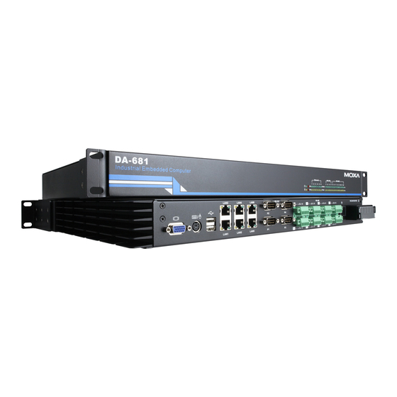
DA-681 Series Hardware User’s Manual Introduction Appearance Front View LED Indicators Power Fail 1 Power Storage 19-inch Power Fail 2 RS-232 RS-485 Rackmount Ear LED Indicators LED Indicators Rear View USB 2.0 RS-485 Serial Port x 8, RS-232 Serial Port x 4, DB9... -
Page 8: Features
DA-681 Series Hardware User’s Manual Introduction 11.9 16.75 Features The DA-681 Basic System has the following features: Intel Celeron M 1 GHz processor with 400 MHz FSB 1 x 200-pin DDR2 SODIMM socket, supporting DDR2 400 up to 1GB (512 Mb built-in) -
Page 9: Hardware Block Diagram
Intel ICH6M South Bridge CF Socket LAN4 SATA LAN5 LAN6 MU860 MU860 PS/2 Super BIOS KB/Mouse RS-232 x 4 RS-485 x8 Hardware Specifications DA-681 series embedded computers support peripheral expansion through two expansion slots located on the DA-681 Basic System. -
Page 10: Basic Systems
DA-681 Series Hardware User’s Manual Introduction Basic Systems DA-681-CE DA-681-LX DA-681-XPE Computer Intel Celeron M 1 GHz processor OS (pre-installed) WinCE 6.0 Linux 2.6 Windows XP Embedded SP2 System Chipset Intel 910GMLE + ICH6M chipset 400 MHz BIOS 4 mega-bit Flash BIOS, PCI Plug & Play, ACPI function support System Memory 1 x 200-pin DDR2 SODIMM socket supporting DDR2 400;... - Page 11 DA-681 Series Hardware User’s Manual Introduction Baudrate 50 bps to 921.6 Kbps (non-standard baudrates supported; see next page for details) Serial Signals RS-232 TxD, RxD, DTR, DSR, RTS, CTS, DCD, GND RS-485-2w Data+, Data-, GND LEDs System Power x 1, Storage x 1, Power 1 Fail x 1, Power 2 Fail x 1...
-
Page 12: Non-Standard Baudrates
DA-681 Series Hardware User’s Manual Introduction Non-standard Baudrates Moxa’s UART ASIC, supports most non-standard baudrates in the range 50 bps to 921.6 Kbps. In fact, supported baudrates are much denser towards the lower values. For example, no baudrates are supported between the integers 5320 and 5323, but 49 baudrates are supported between the integers 387 and 388. - Page 13 DA-681 Series Hardware User’s Manual Introduction WARNING Communication between a serial device and a Moxa UART port may not work correctly if the serial device uses a baudrate that it not within the correct tolerance of a baudrate calculated from...
-
Page 14: Chapter 2 Hardware Installation
Hardware Installation Chapter 2 The DA-681 Series of embedded computers are compact and rugged, making them suitable for industrial applications. The LED indicators allow users to monitor performance and identify trouble spots quickly, and multiple ports are provided for connecting a variety of different devices. -
Page 15: Placement Options
DA-681 Series Hardware User’s Manual Hardware Installation Placement Options Desktop Place your DA-681 on a clean, flat, well-ventilated desktop. For better ventilation, leave some space between the DA-681 and other equipment. Do not place equipment or objects on top of the DA-681, as this might damage the computer’s internal components. - Page 16 DA-681 Series Hardware User’s Manual Hardware Installation Step 2: Installing the rackmount ears to the DA-681. Use 6 screws to attach one rackmount ear to one side of the DA-681. Repeat this procedure for the ear on the other side of the DA-681.
-
Page 17: Wiring Requirements
DA-681 Series Hardware User’s Manual Hardware Installation Note that four screws are required to attach the DA-681 to the rack. Use two screws on the left side and two screws on the right side. As a final check, make sure that the four screws are firmly attached to the rack. -
Page 18: Connecting The Power
DA-681 Series Hardware User’s Manual Hardware Installation ATTENTION Do not run signal or communication wiring and power wiring in the same wire conduit. To avoid interference, wires with different signal characteristics should be routed separately. ATTENTION Safety First! Be sure to disconnect the power cord before installing and/or wiring your device. -
Page 19: Reset Button
DA-681 Series Hardware User’s Manual Hardware Installation PWR 1 PWR 2 Power 2 Power 1 Chasis Ground Shielded Groud When finished, press Power Switch button to start the system. Power Switch Reset Button Pressing the Reset button initiates a hardware warm reboot. The button plays the same role as a desktop PC’s reset button. -
Page 20: Front Panel Led
DA-681 Series Hardware User’s Manual Hardware Installation Front Panel LED There are 40 LED indicators on the front panel. Information about each LED is given in the following table. LED Indicators Power Fail 1 Power Storage RS-232 RS-485 Power Fail 2... -
Page 21: Connecting To A Display
DA-681 Series Hardware User’s Manual Hardware Installation Connecting to a Display Your DA-681 embedded computer comes with a D-Sub 15-pin female connector to connect to the VGA monitor. Be sure to remove the power before you connect or disconnect the monitor cable. -
Page 22: Connecting Usb Devices
DA-681 Series Hardware User’s Manual Hardware Installation Use the Y-type cable to convert the mini-DIN connector into two 6-pin mini-DIN connectors to connect both a PS/2 keyboard and PS/2 mouse at the same time. (The Y-type cable is not included in the accessory package. -
Page 23: Upgrading The Memory Module
DA-681 Series Hardware User’s Manual Hardware Installation Color Description Ethernet Port Green 100 Mbps of Ethernet Port is active 100 Mbps No activity Ethernet Port Yellow 10 Mbps of Ethernet Port is active 10 Mbps No activity The default IP addresses and netmasks of the Gigabit LAN ports are as follows:... - Page 24 DA-681 Series Hardware User’s Manual Hardware Installation However, DDR2 SDRAM memory has been installed already. To upgrade the memory, you need to remove the original memory by pushing two clutches at both sides of the module. Gently insert the new memory into the module. Make sure the direction is correct.
-
Page 25: Installing A Compactflash Card
DA-681 Series Hardware User’s Manual Hardware Installation Push the memory all the way down to complete. Installing a CompactFlash Card The DA-681 embedded computer comes with a CompactFlash socket. To insert a CompactFlash card, follow these instructions. 1. Disconnect the DA-681 from its power source. - Page 26 DA-681 Series Hardware User’s Manual Hardware Installation 3. Insert the CompactFlash card into the socket. Push downwards to make sure that the card is firmly inserted. 2-13...
- Page 27 DA-681 Series Hardware User’s Manual Hardware Installation ATTENTION Make sure you insert the card in the right direction. The card cannot be inserted if you insert the card in the wrong direction. ATTENTION The DA-681 embedded computer does not support the CompactFlash hot swap and PnP (Plug and Play) functions.
-
Page 28: Installing A Sata Hard Disk
DA-681 Series Hardware User’s Manual Hardware Installation Installing a SATA Hard Disk The DA-682 embedded computer has one SATA connector for installing a SATA hard disk. To install a 2.5-inch SATA hard disk, follow these instructions. 1. Disconnect the DA-682 from its power source. - Page 29 DA-681 Series Hardware User’s Manual Hardware Installation 4. Install the SATA hard disk in the hard disk bracket. 5. Next, install the SATA hard disk and hard disk bracket back into the DA-681. Make sure the screws are firmly attached.
- Page 30 DA-681 Series Hardware User’s Manual Hardware Installation ATTENTION The SATA hard disk cable and SATA power cable are not included in the basic shipment of the DA-681 embedded computer. Any standard SATA disk cable and power cable can be used.
-
Page 31: Chapter 3 Bios Setup
BIOS Setup Chapter 3 This chapter describes the BIOS settings of the DA-681 embedded computers. The BIOS is a set of input/output control routines for peripherals. The BIOS is used to initialize basic peripherals and helps boot the operating system before the operating system is loaded. The BIOS setup allows the user to modify the system configurations of these basic input/output peripherals. -
Page 32: Entering The Bios Setup Utility
DA-681 Series Hardware User’s Manual BIOS Setup Entering the BIOS Setup Utility To enter the BIOS setup utility, press the “Del” key while the system is booting up. The main BIOS Setup screen will appear. A basic description of each function key is listed at the bottom of the screen. Refer to these descriptions to learn how to scroll about the screen, how to select by pressing “Enter,”... -
Page 33: System Security
DA-681 Series Hardware User’s Manual BIOS Setup System Security To set up system security, select the “Security” option under “Main” to bring up the following screen. This menu includes two options: “Set Password” and “Security Option.” When you select the Set Password option, a pop-up “Enter Password:” window will appear on the screen. -
Page 34: Advanced Settings
DA-681 Series Hardware User’s Manual BIOS Setup Advanced Settings The “Advanced Features” screen will appear when choosing the “Advanced” item from the main menu. Hard Disk Boot Priority First/Second/Third Boot Device This option allows users to select or change the device boot priority. You may set 3 levels of priority to determine the boot up sequence for different bootable devices, such as a hard drive, CD-ROM, and removable devices. -
Page 35: Cpu Features
DA-681 Series Hardware User’s Manual BIOS Setup CPU Features Virus Warning This item allows you to choose the VIRUS warning feature for IDE hard disk boot sector protection. If this function is enabled and someone attempts to write data into this area, the BIOS will display a warning message on the screen and sound an audio alarm (beep). -
Page 36: Apic Mode
DA-681 Series Hardware User’s Manual BIOS Setup Typematic Rate (Chars/Sec) The rate at which the keyboard will repeat a keystroke if users press key continuously. Typematic Delay (milliseconds) The delay before keystrokes begin to repeat. Options: 250 ms (default), 500 ms, 750 ms, 1000 ms APIC Mode Set the “Advanced Programmable Interrupt Controller”... -
Page 37: Advanced Chipset Settings
DA-681 Series Hardware User’s Manual BIOS Setup Advanced Chipset Settings System BIOS Cacheable The BIOS ROM addresses F0000h to FFFFFh are cached, and the cache controller is enabled to access the system. Enable it to speed up system performance. Options: Enabled (default), Disabled Video BIOS Cacheable Enabling this feature allows the caching of the video BIOS and may improve performance. -
Page 38: Pnp/Pci Configurations
DA-681 Series Hardware User’s Manual BIOS Setup DVMT/FIXED Memory Size Sets the maximum amount of system memory that can be allocated as graphics memory. Options: 64 MB, 128 MB (default). PnP/PCI Configurations Init Display First This item allows you to decide whether the PCI interface or onboard graphic chip is activated first. -
Page 39: Frequency/Voltage Control
DA-681 Series Hardware User’s Manual BIOS Setup Frequency/Voltage Control Spread Spectrum Select “Enabled” to reduce EMI (Electromagnetic Interference). The default is “Enabled.” Peripherals... -
Page 40: Onchip Ide Device
DA-681 Series Hardware User’s Manual BIOS Setup OnChip IDE Device IDE HDD Block Mode Block mode is otherwise known as block transfer, multiple commands, or multiple sector read/write. Select the “Enabled” option if your IDE hard drive supports block mode (most new drives do). -
Page 41: Onboard Device
DA-681 Series Hardware User’s Manual BIOS Setup Onboard Device USB Controller This feature allows you to enable/disable the USB controller. Options: Enabled (default), Disabled USB 2.0 Controller This feature allows you to enable/disable the USB 2.0 controller. Options: Enabled (default), Disabled USB Keyboard Support This item is useful for DOS systems. -
Page 42: Onboard I/O Chip Setup
DA-681 Series Hardware User’s Manual BIOS Setup Onboard I/O Chip Setup Debug Port Select an address and corresponding interrupt for this debug port. This port is only for engineers who are debugging programs. Options: Disabled (default), 3F8/IRQ4 PWRON after PWR-Fail This field determines whether your system will boot after restoring power from a power failure. -
Page 43: Wake Up Control
DA-681 Series Hardware User’s Manual BIOS Setup Soft-Off by PWR-BTTN Select the “Instant-Off” option if you would like the system to power down immediately after pushing the power button. Selecting the “Delay 4 Sec” option will require pushing the power button continuously for at least 4 seconds before the system powers down. -
Page 44: Hardware Monitor
DA-681 Series Hardware User’s Manual BIOS Setup Hardware Monitor CPU Warning Temperature This item sets the CPU warning temperature. When the CPU temperature is higher than this setting, the system will throttle down to 75%. When the CPU temperature is higher than this setting plus 10°C, the system will throttle down to 50%. -
Page 45: Exiting The Bios Setup
DA-681 Series Hardware User’s Manual BIOS Setup Load System Default Settings Use this option to load system factory default settings instead of the current BIOS settings. This option is useful for when the system is unstable. Users do not need to remember what settings were active before the system fails. -
Page 46: Upgrading The Bios
DA-681 Series Hardware User’s Manual BIOS Setup Upgrading the BIOS This section describes how to upgrade the bios. Step 1: Create a Bootable USB Disk. There are two recommended methods for creating a bootable USB disk: Method 1: Use HP USB Disk Format Tool 1. - Page 47 DA-681 Series Hardware User’s Manual BIOS Setup ATTENTION HP’s USB Disk Storage Format Tool can be downloaded from many web sites. Use the phrase “HP USB Disk Storage Format Tool” to search the Internet, and then download the tool from one of the websites that is listed.
- Page 48 DA-681 Series Hardware User’s Manual BIOS Setup Step 3: Set up the BIOS to Boot from the USB Disk. 1. Insert the USB disk. 2. Power on and press DEL to enter the BIOS Setup menu. 3. Select Advanced Hard Disk Boot Priority and then press Enter.
- Page 49 DA-681 Series Hardware User’s Manual BIOS Setup Step 4: Run awdflash.exe to upgrade the BIOS. 1. If the BIOS Setup is correct, it will restart and boot from the USB disk. 2. Run awdflash xxxxxxx.Sxx from the command line to upgrade the BIOS. Replace xxxxxxx.Sxx with the BIOS binary file name discussed in Step 2.
- Page 50 DA-681 Series Hardware User’s Manual BIOS Setup Step 5: Load BIOS Default. 1. When the system reboots, the user should load the CMOS Setup default value again. 2. Press DEL to open the BIOS Setup menu. 3. Select Defaults Load System Default Settings and then choose Y.
- Page 51 Safety Installation Instructions Appendix A A. RTC Battery Warning CAUTION: There is a risk of explosion if battery is replaced by an incorrect type. Dispose of used batteries according to the instructions. B. Fuse Warning CAUTION: For continued protection against fire, replace only with same type and rating of fuse. C.
- Page 52 Regulatory Statement Approval Appendix B This device complies with part 15 of the FCC Rules. Operation is subject to the following two conditions: (1) This device may not cause harmful interference, and (2) this device must accept any interference received, including interference that may cause undesired operation.
Need help?
Do you have a question about the DA-681 Series and is the answer not in the manual?
Questions and answers