Honeywell UDC 2300 User Manual
Universal digital controller
Hide thumbs
Also See for UDC 2300:
- Product manual (186 pages) ,
- Replacement instructions (2 pages) ,
- Product manual (106 pages)

Related Manuals for Honeywell UDC 2300


Summary of Contents for Honeywell UDC 2300
- Page 1 UDC 2300 Universal Digital Controller User Manual 51-52-25-83D 4/00 Sensing and Control...
- Page 2 Specifications may change without notice. The information we supply is believed to be accurate and reliable as of this printing. However, we assume no responsibility for its use. While we provide application assistance personally, through our literature and the Honeywell web site, it is up to the customer to determine the suitability of the product in the application.
- Page 3 This document provides descriptions and procedures for the Installation, Configuration, Operation, and Troubleshooting of your UDC2300 Controller. For a full UDC2300 product manual, request document number 51-52-25-73. Contacts World Wide Web The following lists Honeywell’s World Wide Web sites that will be of interest to our customers. Honeywell Organization WWW Address (URL) Corporate http://www.honeywell.com...
- Page 4 Symbol Definitions The following table lists those symbols used in this document to denote certain conditions. Symbol Definition This CAUTION symbol on the equipment refers the user to the Product Manual for additional information. This symbol appears next to required information in the manual.
-
Page 5: Table Of Contents
Contents INTRODUCTION ....................1 1.1 Overview........................1 1.2 CE Conformity (Europe)....................2 INSTALLATION..................... 3 2.1 Overview........................3 2.2 Preliminary Checks ......................3 2.3 Control and Alarm Relay Contact Information ..............6 2.4 Mounting ........................7 2.5 Wiring ..........................9 2.6 Wiring the Controller ....................11 2.7 Initial Start-up....................... - Page 6 4.5 Setpoints........................45 4.6 Timer ........................... 46 4.7 Accutune II........................47 4.8 Fuzzy Overshoot Suppression ..................47 4.9 Using Two Sets of Tuning Constants................48 4.10 Alarms ......................... 49 4.11 Three Position Step Control Algorithm ................. 50 4.12 Setting a Failsafe Output Value for Restart After a Power Loss........51 4.13 Setting Failsafe Mode ....................
- Page 7 Tables Table 2-1 Preliminary Checks __________________________________________________ 3 Table 2-2 Control Relay Contact Information ______________________________________ 6 Table 2-3 Alarm Relay Contact Information _______________________________________ 6 Table 2-4 Mounting Procedure _________________________________________________ 8 Table 2-5 Permissible Wiring Bundling __________________________________________ 10 Table 2-6 Universal Output Functionality and Restrictions ___________________________ 10 Table 3-1 Configuration Procedure _____________________________________________ 21 Table 3-2 TIMER Group (Numeric Code 100) Function Prompts ______________________ 22 Table 3-3 TUNING Group (Numeric Code 200) Function Prompts _____________________ 23...
- Page 8 Figures Figure 1-1 UDC2300 Operator Interface __________________________________________ 1 Figure 2-1 Jumper Placements _________________________________________________ 5 Figure 2-2 Mounting Dimensions (not to scale) _____________________________________ 7 Figure 2-3 Mounting Method ___________________________________________________ 8 Figure 2-4 Composite Wiring Diagram __________________________________________ 11 Figure 2-5 Mains Power Supply________________________________________________ 12 Figure 2-6 Input 1 Connections ________________________________________________ 12 Figure 2-7 Input 2 Connections ________________________________________________ 12 Figure 2-8 Electromechanical Relay Output ______________________________________ 13...
-
Page 9: Introduction
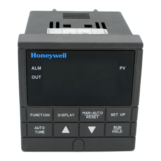
The UDC 2300 is a microprocessor-based stand-alone controller. It combines reliability and operating simplicity in a cost-effective 1/4-DIN size controller. The UDC 2300 monitors and controls temperatures and other variables in applications such as environmental chambers, plastic processing machines, furnaces and ovens, and packaging machinery. -
Page 10: Ce Conformity (Europe)
Introduction 1.2 CE Conformity (Europe) This product is in conformity with the protection requirements of the following European Council Directives: 73/23/EEC, the Low Voltage Directive, and 89/336/EEC, the EMC Directive. Conformity of this product with any other “CE Mark” Directive(s) shall not be assumed. Product Classification: Class I: Permanently connected, panel-mounted Industrial Control Equipment with protective earthing (grounding). -
Page 11: Installation
2 Installation 2.1 Overview Introduction Installation of the UDC 2300 consists of mounting and wiring the controller according to the instructions given in this section. Read the pre-installation information, check the model number interpretation (Appendix B), and become familiar with your model selections, then proceed with installation. - Page 12 Installation Check Preliminary Check Description Number Control Relay 2 and Alarm The controller has been shipped with ALARM Relay Action. relays configured for N.C. (Normally Closed). If you want to change to N.O. refer to Figure 2-1, Jumper positions W201 and W202: W201 is the ALARM RELAY 1 jumper.
-
Page 13: Figure 2-1 Jumper Placements
Installation Jumper Placements Note: Jumpers enlarged for clarity Input #2 Jumper Position 2 S201 S201 Volt Jumper W201 Position 1 W202 Alarm Relay #1 W201 Main Board NC (default) 4 3 2 S101 W101 Output #2/ Alarm Relay #2 W202 NC (default) Input #1 S101... -
Page 14: Control And Alarm Relay Contact Information
Installation 2.3 Control and Alarm Relay Contact Information Control Relays ATTENTION Control relays operate in the standard control mode (that is, energized when output state is on). Table 2-2 Control Relay Contact Information Unit Power Control Relay Control Relay #1 or #2 Output Wiring Contact Indicator Status... -
Page 15: Mounting
Installation 2.4 Mounting Physical Considerations The controller can be mounted on either a vertical or tilted panel using the mounting kit supplied. Adequate access space must be available at the back of the panel for installation and servicing activities. The controller’s mounting enclosure must be grounded according to CSA standard C22.2 No. -
Page 16: Table 2-4 Mounting Procedure
Installation Mounting Method Before mounting the controller, refer to the nameplate on the outside of the case and make a note of the model number. It will help later when selecting the proper wiring configuration. Panel 20752 Figure 2-3 Mounting Method Mounting Procedure Table 2-4 Mounting Procedure Step... -
Page 17: Wiring
Installation 2.5 Wiring Electrical Considerations he controller is considered “rack and panel mounted equipment” per EN61010-1, afety Requirements for Electrical Equipment for Measurement, Control, and aboratory Use, Part 1: General Requirements. Conformity with 72/23/EEC, the ow Voltage Directive requires the user to provide adequate protection against a hock hazard. -
Page 18: Table 2-5 Permissible Wiring Bundling
Installation Use Suppression Devices—For additional noise protection, you may want to add suppression devices at the external source. Appropriate suppression devices are commercially available. ATTENTION For additional noise information, refer to Document #51-52-05-01, How to Apply Digital Instrumentation in Severe Electrical Noise Environments. Permissible Wiring Bundling Table 2-5 Permissible Wiring Bundling Bundle No. -
Page 19: Wiring The Controller
Installation 2.6 Wiring the Controller Using the information contained in the model number, select the appropriate wiring diagrams from the composite wiring diagram below. Refer to the individual diagrams listed to wire the controller according to your requirements. Composite Wiring Diagram Mains Power Supply Input 1 Connections Input 2 Connections... -
Page 20: Figure 2-5 Mains Power Supply
Installation PROTECTIVE BONDING (grounding) of this controller Neutral and the enclosure in which it is installed, shall be in L2 / N accordance with National and Local electrical codes. To Mains minimize electrical noise and transients that may power Ground supply adversely affect the system, supplementary bonding of the controller enclosure to a local ground, using a No. -
Page 21: Figure 2-8 Electromechanical Relay Output
Installation OUT1 OUT2/ALM2 Control Relay #1 Load Load Supply Power 5 amp Fast Blo 24859 1 Control relays 1 and 2 are configured N.O. as shipped. Alarm relays 1 and 2 are configured N.C. as shipped. N.O. or N.C. configurations are selectable by jumpers on the Main printed wiring boards. -
Page 22: Figure 2-10 Open Collector Relay Output
Installation Customer Supplied External Customer Supplied External Solid State Relay Electromechanical Relay OUT2/ALM2 OUT1 0-24 Vdc – 5 – 9 – OUT1 OUT2/ALM2 – 9 – 5– 0-24 Vdc 24861M Open collector outputs are internally powered at 24 Vdc. CAUTION Connecting an external supply will damage the controller. -
Page 23: Figure 2-12 External Solid State Relay Option (Internal Open Collector Output)
Installation 10 amp Fast Blo L1/H 10 Amp Solid State Relay Assembly L2/N LOAD OUTPUT1 OUTPUT2 White Black L2 / N L2 / N Green Green Relay Black Assembly White 24863M This Solid State relay is rated at 15 Amps at 25°C, linearly derated to 10 Amps at 55°C. -
Page 24: Figure 2-14 Alarm And Duplex Output Connections
Communications COMMUNICATION MASTER (RTN) SHLD D– D– 120 OHMS Connect shield wires together with Honeywell TO OTHER COMMUNICATION supplied crimp part number 30755381-001 CONTROLLERS Do not run these lines in the same conduit as AC power. D– 120 OHMS ON LAST LEG 21758B.ppt... -
Page 25: Initial Start-Up
Installation 2 Wire Transmitter 9 – INPUT 1 OUTPUT 2 Configure: A2S1TYPE = NONE A2S2TYPE = NONE Figure 2-16 Transmitter Power for 4-20 mA — 2 wire Transmitter Using Open Collector Alarm 2 Output (Model DC230B-XT-XX-XX-XXXXXXX-XX-X) 2 Wire Transmitter INPUT 1 13 + AUXOUT Configure:... -
Page 26: Operator Interface And Key Functions
Installation Test Failures If one or more of these tests fail, the controller will go to the Failsafe Manual Mode, and FAILSF will flash in the lower display and a message indicating which test failed will appear in the lower display. Then, “DONE” will appear in the lower display. -
Page 27: Configuration
Configuration 3 Configuration 3.1 Overview Introduction Configuration is a dedicated operation where you use straightforward keystroke sequences to select and establish (configure) pertinent control data best suited for your application. To assist you in the configuration process, there are prompts that appear in the upper and lower displays. -
Page 28: Figure 3-1 Prompt Hierarchy
Configuration Figure 3-1 Prompt Hierarchy Set Up Group Function Prompts TIMER TIMER PERIOD START L DISP RESET INCRMT TUNING PB or RATE T I MIN or MANRST PB 2 or RATE2T I2 MIN or CYC T1 GAIN I RPM GAIN 2 I2 RPM CT1 X3 CYC2T2... - Page 29 Configuration Procedure ATTENTION The prompting scrolls at a rate of 2/3 seconds when the SET UP or FUNCTION key is held in. Also, [ ] [ ] keys will move group prompts forward or backward at a rate twice as fast. Table 3-1 Configuration Procedure Step Operation...
-
Page 30: Timer Set Up Group
Configuration 3.3 Timer Set Up Group Introduction The Timer Set Up group allows you to configure a time-out period and to select the timer start by either the keyboard (RUN/HOLD key) or Alarm 2. The optional digital input can also be configured to start the timer. The timer display is selectable as either “time remaining”... -
Page 31: Tuning Set Up Group
Configuration 3.4 Tuning Set Up Group Introduction Tuning consists of establishing the appropriate values for the tuning constants you are using so that your controller responds correctly to changes in process variable and setpoint. You can start with predetermined values but you will have to watch the system to see how to modify them. - Page 32 Configuration Table 3-3 TUNING Group (Numeric Code 200) Function Prompts, continued Prompt Description Selection or Range of Setting Factory Setting English Numeric Numeric English Code Code 1 to 120 CYC T1 or Cycle Time (Heat) Cycle times are in CT1X3 either second or 1/3 second increments...
-
Page 33: Sp Ramp Set Up Group
Configuration 3.5 SP Ramp Set Up Group Introduction A single setpoint ramp [SPRAMP] can be configured to occur between the current local setpoint and a final local setpoint over a time interval of from 1 to 255 minutes. SPRATE lets you configure a specific rate of change for any local setpoint change. - Page 34 Configuration Prompt Description Selection or Range of Setting Factory Setting English Numeric Numeric English Code Code End Segment 2 to 12 (always end in a ENDSEG Number soak segment 2, 4, …12) SOK 2 SOK4 SOK6 SOK8 SOK10 SOK12 Engineering units for TIME (hours:minutes) TIME RPUNIT...
-
Page 35: Accutune Set Up Group
Configuration 3.6 Accutune Set Up Group Introduction Accutune II automatically calculates GAIN, RATE, and RESET TIME (PID) tuning constants for your control loop. When initiated on demand, the Accutune algorithm measures a process step response and automatically generates the PID tuning constants needed for no overshoot on your process. Fuzzy Overshoot Suppression, when enabled, will suppress or eliminate any overshoot that may occur as a result of the existing tuning parameters, as the PV approaches the setpoint. -
Page 36: Algorithm Set Up Group
Configuration 3.7 Algorithm Set Up Group Introduction This data deals with various algorithms in the controller: Control algorithm, Output algorithm, Current Duplex Range, and Relay Cycle Time Increment. Function Prompts Table 3-6 ALGOR Group (Numeric Code 500) Function Prompts Prompt Description Selection or Range of Setting Factory... -
Page 37: Input 1 Set Up Group
Configuration 3.8 Input 1 Set Up Group Function Prompts Table 3-7 INPUT1 Group (Numeric Code 600) Function Prompts Prompt Description Selection or Range of Setting Factory Setting English Numeric Numeric English Code Code DECMAL Decimal Point 8888 (none) 8888 Selection 888.8 88.88 Temperature... - Page 38 Configuration Table 3-7 INPUT1 Group (Numeric Code 600) Function Prompts, continued Prompt Description Selection or Range of Setting Factory Setting English Numeric Numeric English Code Code IN1 HI Input 1 High 2400 999 to 9999 floating Range Value in engineering units Input 1 Low IN1 LO 999 to 9999 floating...
-
Page 39: Input 2 Set Up Group
Configuration Input 2 Set Up Group Function Prompts Table 3-8 INPUT2 Group (Numeric Code 700) Function Prompts Prompt Description Selection or Range of Setting Factory Setting English Numeric Numeric English Code Code Input 2 Type 1-5V IN2TYP 0-20 (mA) 4-20 (mA) 0-5 (Volts) 1-5 (Volts) 0-2 (Volts) -
Page 40: Control Set Up Group
Configuration 3.10 Control Set Up Group Introduction The functions listed in this group deal with how the controller will control the process including: Number of Tuning Parameter Sets, Setpoint Source, Tracking, Power-up Recall, Setpoint Limits, Output Direction and Limits, Deadband, and Hysteresis. - Page 41 Configuration Table 3-9 CONTRL Group (Numeric Code 800) Function Prompts, continued Prompt Description Selection or Range of Setting Factory Setting English Numeric Numeric English Code Code OUT Hi High Output -5 to 105 % of Output Limit (Current) 0.0 to 100.0 % of Output (Relay) OUT Lo Low Output...
-
Page 42: Options Set Up Group
Configuration 3.11 Options Set Up Group Function Prompts Table 3-10 Options Group (Numeric Code 900) Function Prompts Prompt Description Selection or Range of Setting Factory Setting English Numeric Numeric English Code Code Auxiliary Disabled AUXOUT Output Input 1 Input 2 PROC Process Variable Deviation Output... -
Page 43: Communications Set Up Group
Configuration 3.12 Communications Set Up Group Function Prompts Table 3-11 Communications Group (Numeric Code 1000) Prompt Description Selection or Range of Setting Factory Setting English Numeric Numeric English Code Code COMSTA 1001 Communications Disabled State R422 RS-422/485 MODB Modbus 1002 Station Address 1 to 99 ComADD... - Page 44 Configuration Prompt Description Selection or Range of Setting Factory Setting English Numeric Numeric English Code Code 1010 Shed Setpoint LSP Last Local or remote SHD_SP Recall used CSP last Computer Setpoint 1011 Communications PCT Percent UNITS Override Units Eng Engineering Units 1012 Computer -20.0 to 20.0...
-
Page 45: Alarms Set Up Group
Configuration 3.13 Alarms Set Up Group Function Prompts Table 3-12 ALARMS Group (Numeric Code 1100) Function Prompts Prompt Description Selection or Range of Setting Factory Setting English Numeric Numeric English Code Code AxSxVA Alarm Setpointx within the range of the selected 1101 Value parameter or of the PV Span... - Page 46 Configuration UDC2300 Universal Digital Controller User Manual 4/00...
-
Page 47: Operation
Operation 4 Operation 4.1 Powering Up the Controller Apply Power When power is applied, the controller will run three diagnostic tests. After these tests are completed, “TEST DONE” is displayed. Test Failures If one or more of these tests fail, the controller will go to the Failsafe Manual Mode, and FAILSF will flash in the lower display and a message indicating which test failed will appear in the lower display. -
Page 48: Table 4-2 Lower Display Key Parameter Prompts
Operation Viewing the operating parameters Press the DISPLAY key to scroll through the operating parameters listed in Table 4-2. The lower display will show only those parameters and their values that apply to your specific model. Table 4-2 Lower Display Key Parameter Prompts Lower Display Description OUTPUT—Output value is percent;... -
Page 49: Table 4-3 Error Messages
Operation Diagnostic Error Messages The UDC2300 performs background tests to verify data and memory integrity. If there is a malfunction, an error message will be displayed. In the case of more than one simultaneous malfunction, the messages will be displayed sequentially on the lower display. -
Page 50: Single Display Functionality
Operation 4.3 Single Display Functionality Introduction A UDC2300 instrument, which has been configured with a ‘0’ for software options (i.e., DC230x-xx-x0-xx), will only have a single display capability. This means that the displayed value of PV, Setpoint, Setpoint2, Remote Setpoint, Input 2, Output, Bias, Aux Out, and Deviation will appear on the top display and a prompt identifying the value will appear on the bottom display. -
Page 51: Table 4-4 Single Display Parameters
Operation Single Display Parameters Table 4-4 Single Display Parameters Lower Display Prompt Upper Display Value Comments (blank) Process Variable Default selection Process Variable Default selection Local Setpoint #1 Default selection Local Setpoint #2 Default selection Remote Setpoint Default selection Output Deviation Input #2 Aux Output value... -
Page 52: Start Up Procedure For Operation
Operation 4.4 Start Up Procedure for Operation Table 4-5 Procedure for Starting Up the Controller Step Operation Press Result Select Manual MAN/AUTO Until “M” indicator is ON. Mode The controller is in manual mode. RESET N/A for Single Display model. Adjust the [ ] [ ] To adjust the output value and ensure that the final... -
Page 53: Setpoints
Operation 4.5 Setpoints Introduction You can configure the following setpoints for the UDC2300 controller. A Single Local Setpoint (SP) 2 Local Setpoints (SP, 2L) a Local Setpoint and a Remote Setpoint (SP, RS) Switching between setpoints You can switch Local and Remote setpoints or between two Local setpoints when configured. -
Page 54: Timer
Operation 4.6 Timer Introduction The Timer provides a configurable Time-out period of from 0 to 99 hours:59 minutes or 0 to 99 minutes:99 seconds. Timer “Start” is selectable as either the RUN/HOLD key or Alarm 2. The Timer display can be either “Time Remaining” or “Elapsed Time”. Configuration check Make sure: TIMER is enabled... -
Page 55: Accutune Ii
Operation 4.7 Accutune II Operation “TUNE” (Accutune II) algorithm provides foolproof, trouble-free on-demand tuning in the UDC2300 controller. No knowledge of the process is required at start-up. The operator simply initiates the tuning while in the automatic mode. The UDC controller immediately starts controlling to the setpoint while it identifies the process, calculates the tuning constants and enters them into the Tuning group, and begins PID control with the correct tuning parameters. -
Page 56: Using Two Sets Of Tuning Constants
Operation Using Two Sets of Tuning Constants Introduction You can use two sets of tuning constants for single output types and choose the way they are to be switched. (Does not apply for Duplex control.) See table below. Table 4-7 Set Up Procedure Step Operation Press... -
Page 57: Alarms
Operation 4.10 Alarms Introduction An alarm consists of a relay contact and an operator interface indication. The alarm relay is de-energized if setpoint 1 or setpoint 2 is exceeded. The alarm relay is energized when the monitored value goes into the allowed region by more than the hysteresis. -
Page 58: Three Position Step Control Algorithm
Operation 4.11 Three Position Step Control Algorithm Introduction The Three Position Step Control algorithm allows the control of a valve (or other actuator) with an electric motor driven by two controller output relays; one to move the motor upscale, the other to move it downscale, without a feedback slidewire linked to the motor shaft. -
Page 59: Setting A Failsafe Output Value For Restart After A Power Loss
Operation 4.12 Setting a Failsafe Output Value for Restart After a Power Loss Introduction If the power to the controller fails and power is reapplied, the controller goes through the power up tests, then goes to a user configured FAILSAFE OUTPUT VALUE. -
Page 60: Setting Failsafe Mode
Operation 4.13 Setting Failsafe Mode Introduction You can set the Failsafe Mode to be Latching or Non-Latching. Set Failsafe Mode Table 4-12 Procedure for Setting a Failsafe Mode Step Operation Press Result Select Control SET UP Until you see: Set-up Group Upper Display = SET Lower Display = CONTRL Select Failsafe... -
Page 61: Entering A Security Code
Operation 4.14 Entering a Security Code The level of keyboard lockout may be changed in the Set Up mode. However, knowledge of a security code number (0 to 4095) may be required to change from one level of lockout to another. When a controller leaves the factory, it has a security code of 0, which permits changing from one lockout level to another without entering any other code number. -
Page 62: Lockout Feature
Operation 4.15 Lockout Feature Introduction The lockout feature in the UDC2300 is used to inhibit changes (via keyboard) of certain functions or parameters by unauthorized personnel. Lockout levels There are different levels of Lockout depending on the level of security required. These levels are: NONE No Lockout. -
Page 63: Background Tests
Operation 4.16 Background Tests Introduction The UDC2300 performs ongoing background tests to verify data and memory integrity. If there is a malfunction, an error message will be displayed (blinking) in the lower display. In the case of simultaneous malfunctions, the messages will appear in sequence in the lower display. - Page 64 Operation Lower Reason for Failure How to Correct the Problem Display • PV low limit is > PV high limit 1. Check the configuration for each item and CNFERR • SP low limit is > SP high limit reconfigure if necessary. •...
-
Page 65: Restore Factory Calibration
Operation 4.17 Restore Factory Calibration Introduction The factory calibration constants for all the input actuation types that can be used with the controller are stored in its nonvolatile memory. Thus, you can quickly restore the “Factory Calibration” for a given input actuation type by simply changing the actuation type to another type and then changing it back to the original type. - Page 66 Normal operating mode. Return to Normal DISPLAY Operation The factory calibration will be restored. If the problem is not corrected, contact the Honeywell Technical Assistance Center. 1-800-423-9883 USA and Canada UDC2300 Universal Digital Controller User Manual 4/00...
-
Page 67: Setpoint Rate/Ramp/Program Operation
Setpoint Rate/Ramp/Program Operation Setpoint Rate/Ramp/Program Operation 5.1 Setpoint Rate Introduction When you have configured a SETPOINT RATE, it will apply immediately to local setpoint change. Configuration check Make sure: SPRATE is enabled SPRAMP and SPPROG are disabled A Rate Up (EUHRUP) or Rate Down (EUHRDN) value has been configured in Engineering units per hour. -
Page 68: Table 5-1 Running A Setpoint Ramp
Setpoint Rate/Ramp/Program Operation SP RATE and SPPROG are disabled A Ramp Time (TIMIN) in minutes has been configured A final setpoint value (FINLSP) has been configured. See Subsection 3.5 – Configuration group “SPRAMP” for details. Operation Running a Setpoint Ramp includes starting, holding, viewing the ramp, ending the ramp and disabling it. -
Page 69: Setpoint Ramp/Soak Programming
Setpoint Rate/Ramp/Program Operation 5.3 Setpoint Ramp/Soak Programming Introduction Setpoint Ramp/Soak Programming lets you configure six ramp and six soak segments to be stored for use as one program or several small programs. You designate the beginning and end segments to determine where the program is to start and stop. -
Page 70: Table 5-2 Program Contents
Setpoint Rate/Ramp/Program Operation Table 5-2 Program Contents Contents Definition A ramp segment is the time or rate of change it takes to change the Ramp Segments setpoint to the next setpoint value in the program. • Ramps are odd number segments. •... - Page 71 Setpoint Rate/Ramp/Program Operation Contents Definition PV Start This function determines whether LSP1 or PV is used as the setpoint when the program is initially changed from HOLD to RUN. The selections are: DISABL = When the program is initially changed from HOLD to RUN the present LSP1 value is captured as the default setpoint.
-
Page 72: Figure 5-1 Ramp/Soak Profile Example
Setpoint Rate/Ramp/Program Operation Setpoint SEG 8 SEG 9 SEG 4 SG 10 SEG 7 SEG 5 ° SEG 3 SG 11 SEG 2 SEG 6 SEG 1 SG 12 Time/Hours 0 12 13 14 15 20765 Figure 5-1 Ramp/Soak Profile Example Ramp/Soak Profile Example Prompt Function... -
Page 73: Figure 5-2 Program Record Sheet
Setpoint Rate/Ramp/Program Operation Program record sheet Draw your ramp/soak profile on the record sheet shown in Figure 5-2 and fill in the associated information in the blocks provided. This will give you a permanent record of your program and will assist you when entering the Setpoint data. 20766 Figure 5-2 Program Record Sheet Prompt... -
Page 74: Table 5-3 Run/Monitor Functions
Setpoint Rate/Ramp/Program Operation Run/Monitor functions Table 5-3 lists all the functions required to run and monitor the program. Table 5-3 Run/Monitor Functions Function Press Result Set the Local Setpoint DISPLAY Upper Display = PV value Lower Display = SP [ ] [ ] To set the Local Setpoint value to where you want the program to start out. -
Page 75: Appendix A - Environmental And Operating Conditions
Environmental and Operating Conditions 6 Appendix A - Environmental and Operating Conditions Operating Limits Ambient Temperature: 32 °F to 131 °F (0 °C to 55 °C) Relative Humidity: 5 % to 90 % RH up to 104 °F (40 °C) Vibration: Frequency: 0 to 200 Hz Acceleration: 0.6g... - Page 76 Environmental and Operating Conditions UDC2300 Universal Digital Controller User Manual 4/00...
-
Page 77: Appendix B - Model Selection Guide
Model Selection Guide 7 Appendix B - Model Selection Guide D C 2 3 0 B = Basic Controller Model Manuals L = Limit Controller Model 0 _ = English I = Digital Indicator Model F _ = French (Europe) G _ = German (Europe) Output #1 T _ = Italian (Europe) - Page 78 Model Selection Guide UDC2300 Universal Digital Controller User Manual 4/00...
-
Page 79: Appendix C - Configuration Record Sheet
Configuration Record Sheet 8 Appendix C - Configuration Record Sheet Enter the value or selection for each prompt on this sheet so you will have a record of how your controller was configured. Group Value or Factory Group Function Value or Factory Prompt Function Prompt... - Page 80 Configuration Record Sheet Group Value or Factory Group Function Value or Factory Prompt Function Prompt Selection Setting Prompt Prompt Selection Setting INPUT2 IN2TYP _______ 1-5V ComSTA _______ Disable _______ ComADR _______ IN2 HI _______ 2400 SDENAB _______ Enable IN2 LO _______ SHDTIM _______...
- Page 82 Sensing and Control Honeywell 11 West Spring Street Freeport, IL 61032 www.honeywell.com/sensing 51-52-25-83D 0400 Printed in USA...
Need help?
Do you have a question about the UDC 2300 and is the answer not in the manual?
Questions and answers