Table of Contents
Advertisement
Advertisement
Table of Contents
Troubleshooting

Related Manuals for TransAct Printrex 980


Summary of Contents for TransAct Printrex 980
-
Page 1: Operators Guide
Operators Guide 100-11672 Rev D, September 2013... - Page 2 This page intentionally left blank...
-
Page 3: Change History
Change History Revision Changes Date Rev A Initial release September 2012 Rev B Various updates and corrections January 2013 Rev C Add OEM installation and troubleshooting August 2013 content Rev D Changed “Installing the Maintenance Tool September 2013 (Service Utility)” Page 215 100-11672 - Rev D Page i... - Page 4 This page intentionally left blank Page ii 100-11672 - Rev D...
- Page 5 Changes or modifications not expressly approved by TransAct Technologies, Inc. could void the user's authority to operate the equipment.
-
Page 6: Copyright
TransAct Technologies, Inc. ("TransAct"). This document is the property of and contains information that is both confidential and proprietary to TransAct. Recipient shall not disclose any portion of this document to any third party. TRANSACT DOES NOT ASSUME ANY LIABILITY FOR DAMAGES... -
Page 7: Table Of Contents
Table of Contents Change History ....................i Disclaimer ...................... iv Copyright ....................... iv Trademarks ....................iv Table of Contents .................... v ® Introducing your Printrex 980 Printer ..1 ® About your Printrex 980 Printer ..............3 Who Should Read This Guide? ............... 4 What Is Included in This Guide? .............. - Page 8 Paper Loading Procedure (Rear) ..............48 Replacing Ink Tanks ..................54 Replacing the Maintenance Cartridge ............59 Checking the Test Prints ................62 Printing and Examining Nozzle Check Pattern .......... 62 Cleaning Procedure .................. 65 Printing TK-GAP Adjustment Pattern ............67 Examining and Adjusting TK-GAP ............
- Page 9 Spur Marks (Dotted Lines) ..............128 Ink Adhesion (Ink Dripping) ..............129 Defect Recovery Procedures ............... 130 Adjustment ....................137 Adjustment When Replacing Parts ............137 Head Position Adjustment ..............138 Print Module Replacement ..............139 Work at Printhead Replacement ............. 144 Work at Purge Unit Replacement ............
- Page 10 Slow To Print ..................284 Print Quality Is Poor ................284 Appendix A: Ordering Supplies ....285 Drivers Available ..................285 Index ............. 287 Page viii 100-11672 - Rev D...
-
Page 11: Introducing Your Printrex ® 980 Printer
Chapter 1 ® Introducing your Printrex 980 Printer 100-11672 - Rev D Page 1... - Page 12 This page intentionally left blank Page 2 100-11672 - Rev D...
-
Page 13: About Your Printrex ® 980 Printer
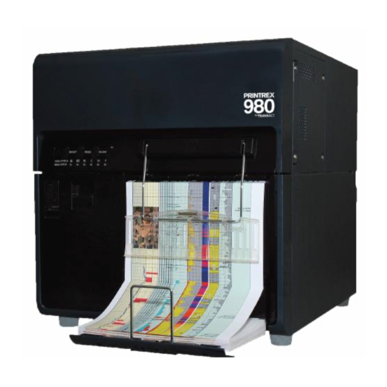
980 Printer ® ® The Printrex 980 printer by TransAct represents the very latest technology for use for high-speed continuous form plotting, specifically designed for the ® needs of the oil and gas industry. It builds upon the experience of the Printrex... -
Page 14: Who Should Read This Guide
Configuration, testing, and troubleshooting procedures ® We want you to have a trouble-free implementation with your TransAct printer. For any issues not covered in this guide, quality technical support is available on-line at www.Transact-tech.com, or by telephone or fax – consult the following pages for more details about our support services. -
Page 15: Technical And Sales Support
About Your Printrex 980 Printer Technical and Sales Support Your printer is backed by the resources of Printrex, a division of TransAct Technologies, a global technology firm with dedicated technical support and sales assistance. Here is how we can help you:... -
Page 16: Return Materials Authorization And Return Policies
To order supplies, receive information about other Printrex products, or obtain information about your warranty, contact our Sales Department at the contact telephone or fax numbers listed below or visit our web site at www.Transact- tech.com. Page 6 100-11672 - Rev D... -
Page 17: Contact Information
® About Your Printrex 980 Printer Contact Information TransAct Technologies Incorporated Ithaca Facility 20 Bomax Drive Ithaca, NY 14850 USA TransAct Technologies World Gaming Headquarters & Western Regional Repair Center 6700 Paradise Road Suite D Las Vegas, NV 89119 USA... - Page 18 ® About Your Printrex 980 Printer Germany Elkutec Electronic GmbH Postfach 11 33 D-85386 Eching bei München Erfurter Straße 31 Germany Telephone (49)-89-31-90-91-0 (49)-89-31-90-91-91 Web Site: www.elkutec.de Email: sales@elkutec.de China Star-Luck Enterprises, Inc. Beijing Office Room 328, Grand Vision Business Building, No.2 Jiuxianqiao Road, Chaoyang District Beijing 100015 China...
-
Page 19: Safety Precautions
Chapter 2 Safety Precautions 100-11672 - Rev D Page 9... - Page 20 This page intentionally left blank Page 10 100-11672 - Rev D...
-
Page 21: Important Safety Precautions
Important Safety Precautions General Precautions Never place items on the printer such as a flower vase, potted plant, cosmetics, any liquid filled container, or metal fasteners. If such items were to fall on the printer, this could cause a fire, electrical shock, or damage to the printer. -
Page 22: Power Supply And Power Cord
Power Supply and Power Cord To avoid the risk of fire, electrical shock, personal injury, or damage to the printer: Always use the power cord provided with this printer. To avoid a fire or electrical shock, do not use an extension cord. ... -
Page 23: Handling The Printer And Accessories
Handling the Printer and Accessories To avoid the risk of fire, electrical shock, personal injury, or damage to the printer: If you find a large ink leak, switch the printer off immediately, disconnect the power plug from the power source, and call for service. ... -
Page 24: Ink Tank And Maintenance Cartridges
Do not place the printer close to devices such as televisions, radio receivers, loudspeakers, etc. The magnetic fields these devices produce may cause the printer to malfunction, and the printer may interfere with TV/radio reception. Note: Be sure to turn off the power switch after the printer has stopped printing. ... -
Page 25: Step-By-Step Installation Procedures
Chapter 3 Step-by-Step Installation Procedures 100-11672 - Rev D Page 15... - Page 26 This page intentionally left blank Page 16 100-11672 - Rev D...
-
Page 27: How To Read This Procedure
Step-by-Step Installation Instructions How to Read This Procedure When Using the Included Parts After unpacking this product, check the included parts against the illustrations shown in “Checking the Included Parts” in this Guide. When the parts supplied with this product are required to be used in the installation procedure, the following symbol indicating that the parts are supplied with the product is shown in the illustration. -
Page 28: Selecting The Installation Site
Step-by-Step Installation Instructions Selecting the Installation Site Installation requirements are listed below. It is recommended that the user’s installation site be checked before delivery of the printer. 1) Power Cord of the printer must connectable to the outlet (100V - 240V AC +10%/-15%) Caution: There must be an easily accessible outlet near the printer. -
Page 29: Checking The Installation Space
Step-by-Step Installation Instructions Checking the Installation Space 1. The minimum space required for installation and maintenance is shown below. 100-11672 - Rev D Page 19... -
Page 30: Installation Precautions
Step-by-Step Installation Instructions Installation Precautions When installing the printer, observe the following precautions: 1) Condensation can occur when the printer is moved from a low-temperature place to a high-temperature installation place. In such a case, leave the printer as it stands for at least 2 hours until it adjusts to the ambient temperature and humidity, before starting the installation work. -
Page 31: Unpacking Printer And Checking The Components
Step-by-Step Installation Instructions Unpacking Printer and Checking the Components 1) Check that the following parts are included: 100-11672 - Rev D Page 21... -
Page 32: Unpacking The Printer And Removing The Fixtures
Step-by-Step Installation Instructions Unpacking the Printer and Removing the Fixtures Note: The printer is secured using fixing tape and cushioning materials to protect it against the vibrations and shocks applied during transportation. By following the procedure described below, remove all pieces of fixing tape and cushioning materials before installing the printer. - Page 33 Step-by-Step Installation Instructions 3) Lift either side of the printer temporarily to remove the 2 lower pads. Next, lift the other side of the printer to remove the remaining 2 lower pads. 4) Strip the plastic bag from the top to the bottom. 100-11672 - Rev D Page 23...
- Page 34 Step-by-Step Installation Instructions 5) Holding the handles at the bottom of the printer, lift the printer to take it out from the package base. Caution: At least 3 persons are required to lift the printer. Do not hold the front side of the printer. Page 24 100-11672 - Rev D...
- Page 35 Step-by-Step Installation Instructions 6) Place the printer on a horizontal table, and then remove all pieces of fixing tape and cushioning material visible on the exterior of the printer. 7) Open Ink Tank Door, and then push Upper Unit Open Lever to open Upper Unit.
- Page 36 Step-by-Step Installation Instructions 9) Close Upper Unit and Ink Tank Door. Page 26 100-11672 - Rev D...
-
Page 37: Mounting Rear Feeder Guide
Step-by-Step Installation Instructions Mounting Rear Feeder Guide 1) Mount the included Rear Feeder Guide on Rear Feeder Slot of Printer using 2 included screws (TP screws, M4×8). 100-11672 - Rev D Page 27... -
Page 38: Loading Ink Tanks
Step-by-Step Installation Instructions Loading Ink Tanks 1) Open Ink Tank Door. 2) Open Ink Tank Lever for each color while pushing it downward. 3) Take included Ink Tank out of Package, and then remove cushioning material. Page 28 100-11672 - Rev D... - Page 39 Step-by-Step Installation Instructions 4) Slowly insert Ink Tank as far as it will go. Caution: Ink Tank cannot be loaded properly if it is inserted in the wrong Ink Tank Slot. Insert Ink Tank securely and push it all the way as far as it will go. 5) Close Ink Tank Lever.
-
Page 40: Initial Loading Of Ink
Step-by-Step Installation Instructions Initial Loading of Ink 1) Connect the included Power Cord to the printer. 2) Connect Power Cord to the outlet. 3) Turn on Main Power Switch. Initial ink loading starts automatically when Main Power Switch is turned on. About 25 minutes are required for initial ink loading. -
Page 41: Printer Part Names And Function
Step-by-Step Installation Instructions Printer Part Names and Function Front View [1] Upper unit Open this unit when set paper or removing the paper jammed in the paper feed path or cleaning inside of the machine. This unit incorporates print modules, PCBs, and so on. [2] Operation panel This panel has the key switches necessary for printer operation and the lamps that indicate printer status. -
Page 42: Back View
Step-by-Step Installation Instructions [8] Stacker unit This unit contains the tray to receive the ejected paper. Draw it out when using Back View [1] LAN port Connect a LAN cable here to connect to the computer. [2] USB port Connect a USB cable here to connect to the computer. [3] Rear feeder slot This slot is used to feed paper exceeding the paper tray capacity. -
Page 43: Inside The Printer
Step-by-Step Installation Instructions Inside the Printer [1] Upper unit release lever Push this lever up to release the upper unit. [2] Paper tray Load paper in this tray. [3] Lift button for paper tray Pressing this button moves the paper tray up and down. [4] Ink tanks Black (Bk), Cyan (C), Magenta (M), and Yellow (Y) ink tanks are loaded. -
Page 44: Operation Panel
Step-by-Step Installation Instructions Operation Panel [1] Power key/lamp Turns power on/off, and wakes the printer up from the sleep mode. Lamp status are as follows: Power-on. Power-off. Blinking Sleep mode. [2] RESET key Pressing this key down for about 1 second during printing cancels all jobs to abort printing. - Page 45 Step-by-Step Installation Instructions [8] Paper residual quantity lamp No paper. Blinking The remaining amount of paper is low. (Only when sheets are supplied through Feeder Lift Tray. Lamp starts flashing when remaining papers become about 100 sheets). Sufficient paper or during paper feed from rear feeder slot. [9] ERROR lamp Operator-call error (can be recovered by user operation).
-
Page 46: Connecting The Communication Cable
Step-by-Step Installation Instructions Connecting the Communication Cable ® The Printrex 980 is equipped with two interface ports. These interfaces are: USB 2.0 Gigabit Ethernet Connect the appropriate communications cable to the printer as shown in the following figures. Cables are provided by your dealer, the system installer or are available through Printrex. -
Page 47: Connect A Lan Cable
Step-by-Step Installation Instructions Note: Whenever connecting a USB cable to the printer, put the USB cable in the cable clamps as shown in the figure. Connect a LAN cable Connect the LAN cable to the printer, as shown in the figure, and then the computer. - Page 48 Step-by-Step Installation Instructions 2. The STATUS lamp stays lit. Note: When the printer is in the sleep mode, press the power key to return the printer to Online mode. Printer will also wake up from the sleep mode automatically as soon as it starts receiving a print job. Page 38 100-11672 - Rev D...
-
Page 49: Switching The Printer Off
Step-by-Step Installation Instructions Switching the Printer Off 1. Press the power key for a few seconds more than one second. Power lamp blinks and the printer enters the sleep mode. 2. Turn off the power switch. If the printer is already in the sleep mode, just turn off the power switch. 100-11672 - Rev D Page 39... -
Page 50: Paper Loading Procedure (Inside)
Step-by-Step Installation Instructions Paper Loading Procedure (Inside) This section describes how to load paper. 1. Make sure that the Power key lamp on the operation lamp stays lit. If the printer has been turned off completely, turn on the main power switch. When the printer is in the sleep mode, press the Power key. - Page 51 Step-by-Step Installation Instructions 4. Open the upper unit. 5. Press the lift button for paper tray. The paper tray moves up. 100-11672 - Rev D Page 41...
- Page 52 Step-by-Step Installation Instructions Note: Do not touch the lifting mechanism while the paper tray is moving up/down. Your fingers could be caught in the machine and this could cause injury. 6. Draw out the paper tray slowly. Page 42 100-11672 - Rev D...
- Page 53 Step-by-Step Installation Instructions 7. Load paper in the paper tray. Load paper with the black mark located on the tip right side of the back of the printing surface. 100-11672 - Rev D Page 43...
- Page 54 Step-by-Step Installation Instructions 8. After loading paper, push the paper tray all the way. 9. Press the lift button for paper tray to move the paper tray down. Note: Follow the same procedure when replacing paper. When the paper tray has been set in position, the "lift"...
- Page 55 Step-by-Step Installation Instructions 10. When the paper tray has moved down completely, draw out the stacker unit, then raise the bar. 11. Pull out paper, and then place paper on the stacker unit. 100-11672 - Rev D Page 45...
- Page 56 Step-by-Step Installation Instructions Note: When setting paper in transport area, place it against paper guides on the right side. Set paper such that it is not slackened. Note: Largely slack paper can jam. To prevent this, pull out paper over the transport unit as straight as possible.
- Page 57 Step-by-Step Installation Instructions Note: Close the upper unit gently to avoid catching your hands, as this may result in personal injury. 13. Paper is automatically fed to the printing position. Note: Load paper in printer immediately after unpacking it. Paper remaining after completion of printing may be held loaded in printer or stored in the paper storage box.
-
Page 58: Paper Loading Procedure (Rear)
Step-by-Step Installation Instructions Paper Loading Procedure (Rear) This section describes the method for loading the paper to be fed from the rear of printer. 1. Make sure that the Power key lamp on the operation lamp stays lit. If the printer has been turned off completely, turn on the power switch. When the printer is in the sleep mode, press the Power key. - Page 59 Step-by-Step Installation Instructions 4. Open the upper unit. 5. When the paper tray has moved down completely, draw out the stacker unit, then raise the bar. 100-11672 - Rev D Page 49...
- Page 60 Step-by-Step Installation Instructions 6. Insert paper in the feeder slot provided on the back of the printer. Note: When supplying paper from the rear of printer, place the paper storage box containing paper below Feeder Slot at the back of printer, at a height that is 100-820 mm lower than Feeder Slot, and then load paper in printer.
- Page 61 Step-by-Step Installation Instructions 7. Pull out paper from the paper tray. 8. Pull out paper, and then place paper on the stacker unit. 100-11672 - Rev D Page 51...
- Page 62 Step-by-Step Installation Instructions Note: When setting paper in transport area, place it against paper guides on the right side. Set paper such that it is not slackened. Note: Largely slack paper can jam. To prevent this, pull out paper over the transport unit as straight as possible.
- Page 63 Step-by-Step Installation Instructions Note: Close the upper unit gently to avoid catching your hands, as this may result in personal injury. 10. Paper is automatically fed to the printing position. Note: Load paper in printer immediately after unpacking it. Paper remaining after completion of printing may be held loaded in printer or stored in the paper storage box.
-
Page 64: Replacing Ink Tanks
Step-by-Step Installation Instructions Replacing Ink Tanks When the ink in an ink tank runs low, the Status Monitor displays [XXXX ink low] message to alert you that ink is about to run out. You can continue to print, and when the ink supply is exhausted, the [Out of XXXX ink] error will be displayed. - Page 65 Step-by-Step Installation Instructions 1. Open the ink tank door. 2. Pull the lever down. 100-11672 - Rev D Page 55...
- Page 66 Step-by-Step Installation Instructions 3. Remove the empty ink tank. Note: Do not touch the ink outlet and terminal to prevent soiling of the the surrounding work area, damage to the ink tank, and poor printing. Note: Never apply excessive force nor drop an ink tank. Ink can stain clothing and the work area.
- Page 67 Step-by-Step Installation Instructions 4. Slowly insert a new ink tank all the way. 5. Close the ink tank lever securely. Note: There are sharp pins in ink tank slots. Never put your fingers into this area. This could cause personal injury or damage the printer. 100-11672 - Rev D Page 57...
- Page 68 Step-by-Step Installation Instructions 6. Close the ink tank door. Note: After installing an ink tank, do not remove it unless you must replace it. This could shorten the life of the consumables. Complete the ink tank replacement procedure as quickly as possible. Do not leave the printer with ink tanks removed.
-
Page 69: Replacing The Maintenance Cartridge
Step-by-Step Installation Instructions Replacing the Maintenance Cartridge When there remains no maintenance cartridge space to collect ink, an error message, “Maintenance Cartridge full,” is displayed on the status monitor, and printing stops. Replace the maintenance cartridge with a new one. Note: For safety, keep the Maintenance Cartridge out of the reach of children. - Page 70 Step-by-Step Installation Instructions 2. Draw out the maintenance cartridge slowly. 3. Take out new maintenance cartridge from a box. 4. While lifting the eject guide slightly, insert a new maintenance cartridge. Page 60 100-11672 - Rev D...
- Page 71 Step-by-Step Installation Instructions 5. While lifting the eject guide slightly, close the maintenance cartridge door. 6. Put the used maintenance cartridge in a bundled plastic bag and dispose of Note: Please dispose the old maintenance cartridge according to federal, state and local laws after being packed in a bundled plastic bag and placed in the box.
-
Page 72: Checking The Test Prints
Step-by-Step Installation Instructions Checking the Test Prints Make the following test prints and confirm that all the print images are correctly tuned. Should the image in each test print need to be tuned, take an adjustment procedure corresponding to each test print: ... - Page 73 Step-by-Step Installation Instructions 4) Open the [Test Print, Adjustment] tab of the "980 Service Utility" dialog box. 5) Click [Nozzle Check Pattern] to print the nozzle check pattern. 100-11672 - Rev D Page 63...
- Page 74 Step-by-Step Installation Instructions 6) Check the printed nozzle check pattern. If a non-discharge is detected, perform cleaning with reference to the next section “Cleaning Procedure”. Page 64 100-11672 - Rev D...
-
Page 75: Cleaning Procedure
Step-by-Step Installation Instructions Cleaning Procedure 1) Open the [Cleaning, User Setting] tab of the "980 Service Utility" dialog box. 2) Select Print Module to be cleaned. 100-11672 - Rev D Page 65... - Page 76 Step-by-Step Installation Instructions 3) Perform the printhead cleaning according to the table below. Mode Time required for Description cleaning Light Cleaning About 0.5 If an ink injection problem is detected, perform minutes “Light Cleaning” first. If the problem persists even Medium About 3 minutes after “Light Cleaning”...
-
Page 77: Printing Tk-Gap Adjustment Pattern
Step-by-Step Installation Instructions Printing TK-GAP Adjustment Pattern 1) Open the [Test Print, Adjustment] tab and click [Adjust TK-GAP] to display the "Print TK-GAP" dialog box. 2) Click [Print] to print the TK-GAP adjustment pattern. 100-11672 - Rev D Page 67... -
Page 78: Examining And Adjusting Tk-Gap
Step-by-Step Installation Instructions Examining and Adjusting TK-GAP 1) Observe the TK-GAP Adjustment Pattern and examine if the TK-GAP adjustment is necessary for Print Modules according to the following. Perform the adjustment, if necessary. Find where the paper perforation is located on the TK-GAP adjustment pattern scale. - Page 79 Step-by-Step Installation Instructions 2) Enter the adjustment values in the TK-GAP adjustment value entry boxes in the "Print TK-GAP" dialog box. 3) After entering the TK-GAP adjustment values, click [Send] to send the adjustment values to Printer. 4) If the TK-GAP adjustment pattern is not required to print again for a review, click [NO] and proceed to the step 6).
- Page 80 Step-by-Step Installation Instructions 5) If the TK-GAP adjustment pattern is desired for reviewing, click [Yes]. 6) Click [Next] to proceed to the slant adjustment. Page 70 100-11672 - Rev D...
-
Page 81: Printing Slant Adjustment Pattern
Step-by-Step Installation Instructions Printing Slant Adjustment Pattern 1) Open the [Test Print, Adjustment] tab and click [Adjust Slant] to display the "Print Head Slant" dialog box. 2) Click [Print] to print the slant adjustment pattern. 100-11672 - Rev D Page 71... -
Page 82: Examining And Adjusting Slant
Step-by-Step Installation Instructions Examining and Adjusting Slant 1) Read values at which Black lines are in line with line of each color (Cyan, Magenta, or Yellow). When a value of A is the same as a value of B: • Example 1: When the value of C1A (+2) is the same as the value of C1B (+2), no adjustment is required for C1 (Cyan Printhead 1). - Page 83 Step-by-Step Installation Instructions 2) Enter necessary adjustment values in the slant adjustment value entry boxes in the "Print Head Slant" dialog box. 3) After entering the slant adjustment values, click [Send] to send the adjustment values to Printer. 4)If the slant adjustment pattern is not required to print again for a review, click [NO] and proceed to the step 6).
- Page 84 Step-by-Step Installation Instructions 5) If the slant adjustment pattern is desired for reviewing, click [Yes]. 6) Click [Next] to proceed to the head position adjustment. Page 74 100-11672 - Rev D...
-
Page 85: Printing Head Position Adjustment Pattern
Step-by-Step Installation Instructions Printing Head Position Adjustment Pattern 1) Open the [Test Print, Adjustment] tab and click [Adjust Position] to display the "Print Head Position Adjustment" dialog box. 100-11672 - Rev D Page 75... - Page 86 Step-by-Step Installation Instructions 2) Click [Print] to print the head position adjustment pattern. Page 76 100-11672 - Rev D...
-
Page 87: Examining And Adjusting Printhead Position
Step-by-Step Installation Instructions Examining and Adjusting Printhead Position 1) Module-to-Module Adjustment This adjustment is to align the relative print positions of 2 Print Modules to each other. The relative print positions in the feeding direction can be examined in the "KV"... - Page 88 Step-by-Step Installation Instructions 2) Head Position Adjustment This adjustment is to align the relative color registrations in all the printheads. The relative color registrations in the feeding direction can be examined in the "xxV" scale and the ones in the cross-feeding direction can be examined in the "xxH"...
- Page 89 Step-by-Step Installation Instructions 3) Enter adjustment values in the Module-to-Module adjustment value entry boxes in the "Print Head Position Adjustment" dialog box. 100-11672 - Rev D Page 79...
- Page 90 Step-by-Step Installation Instructions 4) Click [Go to Step 3]. Page 80 100-11672 - Rev D...
- Page 91 Step-by-Step Installation Instructions 5) Enter the adjustment values in the Head Position Adjustment value entry boxes. 100-11672 - Rev D Page 81...
- Page 92 Step-by-Step Installation Instructions 6) Click [Go to Step 4]. Page 82 100-11672 - Rev D...
- Page 93 Step-by-Step Installation Instructions 7) Enter the adjustment values in the Head Position Adjustment value entry boxes. 100-11672 - Rev D Page 83...
- Page 94 Step-by-Step Installation Instructions 8) Click [Send] to send all the adjustment values to Printer. 9) If the head position adjustment pattern is not required to print again for a review, click [NO] and proceed to step 10. 10) If the head position adjustment pattern is desired for reviewing, click [Yes]. Page 84 100-11672 - Rev D...
- Page 95 Step-by-Step Installation Instructions 11)Press Power Key for at least 1 second to place Printer in the sleep mode (Power Lamp blinks), and then turn off Main Power Switch. 100-11672 - Rev D Page 85...
-
Page 96: Action Of Relocating Printer
Step-by-Step Installation Instructions Action of Relocating Printer The Printer is filled with ink in its Ink Supply System, Imaging System and elsewhere. Implement items suggested below thoroughly and explain to customers fully to prevent ink spills in or outside Printer or to avoid unexpected failures when Printer is transported. - Page 97 Step-by-Step Installation Instructions 2) When the following message is displayed, click [Yes] to drain remaining ink in Purge Unit. Note: Ink drainage takes approximately 2 minutes. The time might be changed due to the specification change. Long Distance Relocation Printer required to return ink from Print Module to Ink Tank and to drain (suction) remaining ink in Purge Unit before shipping Printer long distance.
- Page 98 Step-by-Step Installation Instructions 3) When the following message is displayed, click [Yes] to start return ink from Print Module to Ink Tank, and wait for a while. Note: Ink returning and drainage takes approx. 20 minutes. The time might be changed due to the specification change. 4) When the following message is displayed, remove Ink Tanks, and then close Ink Tank Door.
- Page 99 Step-by-Step Installation Instructions 5) When the following message is displayed, turn off Main Power Switch. 100-11672 - Rev D Page 89...
-
Page 101: Specifications And Requirements
Chapter 4 ® Printrex 980 Specifications and Requirements 100-11672 - Rev D Page 91... - Page 102 This page intentionally left blank Page 92 100-11672 - Rev D...
-
Page 103: Printrex ® 980 Specifications And Requirements
® Printrex 980 Specifications and Requirements ® Printrex 980 Specifications and Requirements Standard Features ® The following features are standard for Printrex 980 printers: Massively parallel bubble jet technology 8 inches per second plot speed 9.25" wide media, 8.25" (216 mm) print width ... -
Page 104: Physical Printer Specifications
® Printrex 980 Specifications and Requirements Physical Printer Specifications 15.5" 20.0" 19.0" Max Dimensions Dimensions in 15.5 20.0 19.0 inches Weight: approx. 123 lbs. (56 kg) Interface USB 2.0 High Speed and Gigabit Ethernet Environmental Conditions ® The Printrex 9800 is designed to be placed on a flat, stable surface that can support the weight of the printer (about 123 lbs. -
Page 105: Electrical Specifications
® Printrex 980 Specifications and Requirements Electrical Specifications 100 VAC - 240 VAC, 50-60 Hz 650 watts maximum Media Specifications Paper Paper feed method Friction feed Paper width 9.25 inches Paper thickness 0.003 - 0.0035 inches USB Interface The USB interface is a Version 2.0 interface card is implemented through a standard Series "B"... -
Page 107: Printer Maintenance
Chapter 5 Printer Maintenance 100-11672 - Rev D Page 97... - Page 108 This page intentionally left blank Page 98 100-11672 - Rev D...
-
Page 109: Cleaning The Printer
® How to Operate the Printrex 980 Printer Cleaning the Printer As the printer is used, ink and paper dust will be collected inside the printer. If the interior of the printer becomes dirty, this will cause printouts to become dirty, affect print quality, or interfere with smooth paper feeding. - Page 110 ® How to Operate the Printrex 980 Printer 2. Turn off the main power switch, and then remove the power plug from the wall outlet. 3. Open the ink tank door. Page 100 100-11672 - Rev D...
- Page 111 ® How to Operate the Printrex 980 Printer 4. Push the upper unit release lever up to open the Upper unit. 5. Open the upper unit. 100-11672 - Rev D Page 101...
- Page 112 ® How to Operate the Printrex 980 Printer 6. Wipe off ink, dust and paper dust adhered around transport and upper unit’s bottom areas (spur, roller, paper ejection slot) with a cloth dipped in water and tightly wrung out. Note: Do not clean the printer with tissues or paper towels. Torn pieces of paper or paper dust may get inside the printer and cause malfunctions.
- Page 113 ® How to Operate the Printrex 980 Printer 7. Close the upper unit and then close the ink tank door. 100-11672 - Rev D Page 103...
-
Page 114: Clearing Paper Jams
® How to Operate the Printrex 980 Printer Clearing Paper Jams If the paper jams while the printer is printing, the printer will stop and the Status Monitor will display a paper jam message. Follow the procedure below to remove the jammed paper. 1. - Page 115 ® How to Operate the Printrex 980 Printer 3. Cut the paper along the perforation. 100-11672 - Rev D Page 105...
-
Page 116: Moving The Printer
® How to Operate the Printrex 980 Printer Moving the printer After moving the printer on the same floor or to another floor, install it properly following the procedure described below. 1. Press the Power key to place the printer in the sleep mode. If the printer is already in sleep mode, go to step 2. - Page 117 ® How to Operate the Printrex 980 Printer 5. Move the printer. Note: To move the printer on the same floor or within the same building, the ink tanks need not be removed. If the ink tanks are removed before moving the printer, ink can leak from the needle sections in the ink tank slots, which may stain clothes and/or the surrounding work area.
- Page 118 ® How to Operate the Printrex 980 Printer 8. After completion of the initial operation, the printer is ready for printing. Page 108 100-11672 - Rev D...
-
Page 119: Shipping The Printer
® How to Operate the Printrex 980 Printer Shipping the Printer When transporting printer over a long distance, observe the following procedures: Contact Printrex technical support for advice before you ship the printer a long distance or move the printer via car, truck or airplane. Moving the printer without proper preparation could subject it to shock and vibration, which could damage the printer and/or cause a fire. -
Page 121: Troubleshooting
Chapter 6 Troubleshooting 100-11672 - Rev D Page 111... - Page 122 This page intentionally left blank Page 112 100-11672 - Rev D...
-
Page 123: Initial Check Items
Appendix A: Ordering Genuine Ithaca Supplies Initial Check Items Checking the Installation Environment Check whether the installation place meets the following requirements: 1) The power supply voltage must be the rated voltage from -15% to +10% and the power supply frequency must be the rated frequency ±2Hz. 2) The printer must be held horizontal. -
Page 124: Procedures For Operation Failure
Appendix B: Frequently Asked Questions Procedures for Operation Failure Paper dust falling from the paper pass on the reflecting plate may reflect the light to the receiving of Rear Feeder Sensor and/or Trailing Edge Sensor. Those reflecting plates need to be cleaned. Rear Feeder Sensor Cleaning 1) Remove Right Cover.("Removing Right Cover"... -
Page 125: Trailing Edge Sensor Cleaning
Appendix A: Ordering Genuine Ithaca Supplies Trailing Edge Sensor Cleaning 1) Open Upper Unit. 2) Wipe reflecting plate with a cotton swab. 100-11672 - Rev D Page 115... -
Page 126: Image Defect Recovery
Appendix B: Frequently Asked Questions Image Defect Recovery Samples of image defects that can be detected through test printing are described below. When an image defect is found, carry out test printing to determine the image defect type, and then perform an appropriate procedure. Vertical White Streak (Non-Discharge) This is a state in which ink drops cannot be discharged from Printhead nozzles due to dust, bubbles, thickened ink, wetting, etc. -
Page 127: Faint Image (Distortion)
Appendix A: Ordering Genuine Ithaca Supplies Faint Image (Distortion) This is a state in which ink drops cannot be discharged from Printhead nozzles due to dust, bubbles, thickened ink, wetting, etc. around Printhead nozzle, or a state in which a condensed ink film is formed on the surfaces of Printhead nozzles, and as a result ink drops are not ejected. -
Page 128: Void
Appendix B: Frequently Asked Questions Void This is a state in which a void is generated due to defective parts of Printhead, Flexible Cable, PCB, etc. or a bad connection. Page 118 100-11672 - Rev D... -
Page 129: Abnormal Discharge
Appendix A: Ordering Genuine Ithaca Supplies Abnormal Discharge This is a state in which ink is ejected to an area having no image data due to defective parts of the Printhead, Flexible Cable, PCB, etc. or a bad connection. 100-11672 - Rev D Page 119... -
Page 130: Uneven Image (Cross Feeding Direction)
Appendix B: Frequently Asked Questions Uneven Image (Cross Feeding Direction) This is a state in which stripes differing in thickness are generated in the longitudinal direction of the Printhead. Page 120 100-11672 - Rev D... -
Page 131: Uneven Image (Feeding Direction)
Appendix A: Ordering Genuine Ithaca Supplies Uneven Image (Feeding Direction) This is a state in which stripes differing in thickness are generated in the transport direction. 100-11672 - Rev D Page 121... -
Page 132: Relative Misregistration In Colors In X Or Y Direction
Appendix B: Frequently Asked Questions Relative Misregistration in Colors in X or Y Direction This is a state in which registration positions of individual colors are deviated, and as a result colors look shifted. Page 122 100-11672 - Rev D... -
Page 133: Misregistration (Leading Edge And Side Edge)
Appendix A: Ordering Genuine Ithaca Supplies Misregistration (Leading edge and side edge) Print image coordinate is not aligned with the paper. The following sample shows misregistration in the side edge. 100-11672 - Rev D Page 123... -
Page 134: Blank Image
Appendix B: Frequently Asked Questions Blank Image This is a state in which the print sheet is ejected with no image printed on it. Page 124 100-11672 - Rev D... -
Page 135: Paper Skew
Appendix A: Ordering Genuine Ithaca Supplies Paper Skew This is a state in which an image is printed on a skew in relation to the left and right edges of the print sheet. 100-11672 - Rev D Page 125... -
Page 136: Spur Marks (White Dotted Lines)
Appendix B: Frequently Asked Questions Spur Marks (White Dotted Lines) This is a state in which pressed Spur marks are made on the print sheet. Page 126 100-11672 - Rev D... -
Page 137: Ink Smearing (Due To Printhead Crash)
Appendix A: Ordering Genuine Ithaca Supplies Ink Smearing (Due to Printhead Crash) This is a state in which the print sheet touches the Printhead and is stained with ink. 100-11672 - Rev D Page 127... -
Page 138: Spur Marks (Dotted Lines)
Appendix B: Frequently Asked Questions Spur Marks (Dotted Lines) This is a state in which ink is transferred to Spur or Spur cleaner due to ink dripping, fixing error, etc. and as a result Spur ink marks are made on the print sheet. -
Page 139: Ink Adhesion (Ink Dripping)
Appendix A: Ordering Genuine Ithaca Supplies Ink Adhesion (Ink Dripping) This is a state in which ink collected in Printhead or Purge Unit drips off to transport area, and as a result ink adheres to the front/back surface of the print sheet. -
Page 140: Defect Recovery Procedures
Appendix B: Frequently Asked Questions Defect Recovery Procedures Vertical White Streak or Faint Image Cause Procedure Check Item Action Ink Supply Carry out Light Cleaning, Medium System Cleaning, and Strong Cleaning 2 or 3 times for each cleaning, and then check that the defect has been recovered. - Page 141 Appendix A: Ordering Genuine Ithaca Supplies *1 Reconnection Recovery Procedure: 1) Service Utility > Troubleshooting 2) Choose Print Module #1 and/or #2 3) Click "Head Install Position" 4) Turn off the power. 5) Remove covers. 6) Rotate up Upper Printhead Release Lever until it stops. 7) Rotate down Upper Printhead Release Lever until it stops.
- Page 142 Appendix B: Frequently Asked Questions Void or Abnormal Discharge (Test Printing Result: OK) Cause Procedure Check Item Action Interface Interface Cable is not connected Connect it Cable securely. properly. The cable has a defect such as Replace the disconnection or crack. cable.
- Page 143 Appendix A: Ordering Genuine Ithaca Supplies Cause Procedure Check Item Action Replace Transport Unit, and then check that the defect has been recovered. Printhead Replace Printhead, and then check that the defect has been recovered. Printer Replace Printer Controller PCB, and Controller then check that the defect has been recovered.
- Page 144 Appendix B: Frequently Asked Questions Misregistration (Leading edge and side edge) Cause Procedure Check Item Action Paper Dedicated paper is not used. Replace with dedicated paper. Paper is not loaded properly. Load paper properly. Paper Setup The type and size of paper used are not Properly set the set properly.
- Page 145 Appendix A: Ordering Genuine Ithaca Supplies Spur Marks (White Dotted Lines) Cause Procedure Check Item Action Paper Dedicated paper is not used. Replace with dedicated paper. Spur Unit The unit is not installed properly. Reinstall it properly. Spur does not rotate smoothly. Replace Spur Unit.
- Page 146 Appendix B: Frequently Asked Questions Spur Marks (Dotted Lines) Cause Procedure Check Item Action Paper Dedicated paper is not used. Replace with dedicated paper. Spur Unit Clean Spur and Spur Cleaner, and then End. check that the defect has been recovered.
-
Page 147: Adjustment
Appendix A: Ordering Genuine Ithaca Supplies Adjustment Adjustment When Replacing Parts This section describes the works to be carried out, as an after-sale service, after parts replacement. Target Parts Adjustment Item Reference section in manual Print Module Print Modules in "Work at Print Module Replacement"... -
Page 148: Head Position Adjustment
Appendix B: Frequently Asked Questions Head Position Adjustment This section describes the works to be carried out when adjusting the basic Head position. Item Standard Reference Value T-K gap 0.5±1.0mm "Head Position Adjustment" adjustment Head position ±100μm "Head Position Adjustment" adjustment Page 138 100-11672 - Rev D... -
Page 149: Print Module Replacement
Appendix A: Ordering Genuine Ithaca Supplies Print Module Replacement Note: Print Module adjustment procedure must be operate on a flat table. Gap between Print Module and the table must be less than 0.5mm. 1) Attach Print Module Joint Plate 1 to Print Module 2 (when replacing Print Module 2). - Page 150 Appendix B: Frequently Asked Questions 3) Adjust Print Modules in place. Adjustment 1: 1) Place two wrenches in a L-shape to adjust the horizontal position. Place the ruler against the end face of Print Module. 2) Tighten the screws to fix Print Module Joint Plate 1. •...
- Page 151 Appendix A: Ordering Genuine Ithaca Supplies Adjustment 2: 1) Place a wrench and Print Module Height Fixture B between Print Modules 1 and 2.. 100-11672 - Rev D Page 141...
- Page 152 Appendix B: Frequently Asked Questions 2) Secure Print Modules 1 and 2. • 4 screws 3) Attach Print Module Height Fixture B. • 2 screws Note: Do not rotate red screw. When attaching Print Module Height Fixture B, place it against the table, and then secure it using the screws.
- Page 153 Appendix A: Ordering Genuine Ithaca Supplies 4) Attach Print Module Top Plate. • 10 screws Adjustment Value Input 1) Input adjustment Values. ("Print Module Replacement Procedure" section) Head Position Adjustment 1) Adjust Head position.("Head Position Adjustment" section) 100-11672 - Rev D Page 143...
-
Page 154: Work At Printhead Replacement
Appendix B: Frequently Asked Questions Work at Printhead Replacement Head Position Adjustment 1) Adjust Head position. ("Head Position Adjustment" section) Work at Purge Unit Replacement Blade Position Adjustment 1) Loosen the screw by 1 turn. 2) Set the key pins on holder of Blade with Blade Adjustment Tool. Set Blade Adjustment Tool in Print Module. -
Page 155: Work At Transport Unit Replacement
Appendix A: Ordering Genuine Ithaca Supplies 3) Tighten the screw. 4) Remove Blade Adjustment Tool. ● Purge Unit Wipe Position Adjustment 1) Enter "Rec wipe P number" that was noted before install the new Purge Unit to "Purge Unit wipe position" using service utility after turning Main Power Switch on. - Page 156 Appendix B: Frequently Asked Questions If the gray areas of backfeed pattern have overlapped at right side, shift the plate to "A" direction. If the gray areas of backfeed pattern have overlapped at left side, shift the plate to "B" direction. Go to the <Adjustment Procedure> section below. Adjustment Procedure: 1) Remove Top Cover and insert the screwdriver to the hole.
- Page 157 Appendix A: Ordering Genuine Ithaca Supplies 2) Loosen the screw. Note: Loosen the screw that located at center only. Screws at both side support the plate of Pinch Roller. 3) Shift the plate of Pinch Roller all the way and tighten the screw. Head Position Adjustment 1) Adjust Head position.
-
Page 158: Work At Rack Unit Replacement
Appendix B: Frequently Asked Questions Work at Rack Unit Replacement 1) Adjust Rack Unit at same position as noted number that was noted when Rack Unit was removed, and then tighten screws. Rear Feeder Sensor Adjustment 1) Insert paper in the feeder slot provided on the back of Printer more than 1 sheet to cover Rear Feeder Sensor. - Page 159 Appendix A: Ordering Genuine Ithaca Supplies 2) Connect PC to Printer, and then start service utility. Open [Parts Replacement] tab, and then click [Adjust] to adjust Rear Feeder Sensor. 3) Confirm that Rear Feeder Sensor is "ON". 100-11672 - Rev D Page 149...
- Page 160 Appendix B: Frequently Asked Questions 4) Remove the paper from feeder slot provided on the back of Printer, and then confirm that Rear Feeder Sensor is "OFF". Page 150 100-11672 - Rev D...
-
Page 161: Work At Stacker Rail And/Or Front Tray Unit Replacement
Appendix A: Ordering Genuine Ithaca Supplies Work at Stacker Rail and/or Front Tray Unit Replacement 1) Prefix Front Tray Unit using screws. • 2 screws 2) Draw out Stacker Rail Until it stops, and then put a bundle of fanfold paper on Front Tray. -
Page 162: Work At Printer Controller Pcb Replacement
Appendix B: Frequently Asked Questions 4) Remove the paper from Front Tray Unit. 5) Tighten the screws to secure Front Tray Unit that was prefixed in step 1). Work at Printer Controller PCB Replacement Before Printer Controller PCB Replacement: 1) Connect PC to Printer, and then start service utility. 2) Retrieve the date from Printer Controller PCB to PC. -
Page 163: Work At Dc Power Supply Pcb Unit Replacement
Appendix A: Ordering Genuine Ithaca Supplies 5) Input Printer serial number. ("Printer Controller PCB Replacement Procedure" section) 6) Set time. ("Time Setting" section) 7) Input adjustment values . ("Print Module Replacement Procedure" section) 8) Adjust Rear Feeder Sensor. ("Rear Feeder Sensor Adjustment" section) 9) Adjust ink eject power. -
Page 164: Head Position Adjustment
Appendix B: Frequently Asked Questions Head Position Adjustment TK-GAP Adjustment Printing TK-GAP Adjustment Pattern 1) Connect PC to Printer, and then start service utility. Open the [Test Print, Adjustment] tab and click [Adjust TK-GAP] to display the "Print TK-GAP" dialog box. Page 154 100-11672 - Rev D... - Page 165 Appendix A: Ordering Genuine Ithaca Supplies 2) Click [Print] to print the TK-GAP adjustment pattern. Examining and Adjusting TK-GAP 1) Observe the TK-GAP Adjustment Pattern and examine if the TK-GAP adjustment is necessary for Print Modules according to the following. Perform the adjustment, if necessary.
- Page 166 Appendix B: Frequently Asked Questions 2) Enter the adjustment values in the TK-GAP adjustment value entry boxes in the "Print TK-GAP" dialog box. Page 156 100-11672 - Rev D...
- Page 167 Appendix A: Ordering Genuine Ithaca Supplies 3) After entering the TK-GAP adjustment values, click [Send] to send the adjustment values to Printer. 4) If the TK-GAP adjustment pattern is not required to print again for a review, click [No] and proceed to step 6). 5) If you wish to review the TK-GAP adjustment pattern, click [Yes].
-
Page 168: Slant Adjustment
Appendix B: Frequently Asked Questions 6) Click [Next] to proceed to the slant adjustment. Slant Adjustment Printing Slant Adjustment Pattern 1) Connect PC to Printer, and then start service utility. Open the [Test Print, Adjustment] tab and click [Adjust Slant] to display the "Print Head Slant"... - Page 169 Appendix A: Ordering Genuine Ithaca Supplies 2) Click [Print] to print the slant adjustment pattern. 100-11672 - Rev D Page 159...
- Page 170 Appendix B: Frequently Asked Questions ● Examining and Adjusting Slant 1) Read values at which Black lines are in line with line of each color (Cyan, Magenta, or Yellow). When a value of A is the same as a value of B: •...
- Page 171 Appendix A: Ordering Genuine Ithaca Supplies 2) Enter necessary adjustment values in the slant adjustment value entry boxes in the "Print Head Slant" dialog box. 100-11672 - Rev D Page 161...
- Page 172 Appendix B: Frequently Asked Questions 3) After entering the slant adjustment values, click [Send] to send the adjustment values to Printer. 4)If the slant adjustment pattern is not required to print again for a review, click [No] and proceed to step 6). 5) If you wish to review the slant adjustment pattern, click [Yes].
- Page 173 Appendix A: Ordering Genuine Ithaca Supplies 6) Click [Next] to proceed to the head position adjustment. 100-11672 - Rev D Page 163...
-
Page 174: Head Position Adjustment
Appendix B: Frequently Asked Questions Head Position Adjustment Printing Head Position Adjustment Pattern 1) Connect PC to Printer, and then start service utility. Open the [Test Print, Adjustment] tab and click [Adjust Position] to display the "Print Head Position Adjustment" dialog box. Page 164 100-11672 - Rev D... - Page 175 Appendix A: Ordering Genuine Ithaca Supplies 2) Click [Print] to print the head position adjustment pattern. 100-11672 - Rev D Page 165...
- Page 176 Appendix B: Frequently Asked Questions Examining and Adjusting Printhead Position 1) Module-to-Module Adjustment This adjustment is to align the relative print positions of 2 Print Modules to each other. The relative print positions in the feeding direction can be examined in the "KV"...
- Page 177 Appendix A: Ordering Genuine Ithaca Supplies 2) Head Position Adjustment This adjustment is to align the relative color registrations in all Printheads. The relative color registrations in the feeding direction can be examined in the "xxV" scale and the ones in the cross-feeding direction can be examined in the "xxH"...
- Page 178 Appendix B: Frequently Asked Questions 3) Enter adjustment values in the Module-to-Module adjustment value entry boxes in the "Print Head Position Adjustment" dialog box. Page 168 100-11672 - Rev D...
- Page 179 Appendix A: Ordering Genuine Ithaca Supplies 4) Click [Go to Step 3]. 100-11672 - Rev D Page 169...
- Page 180 Appendix B: Frequently Asked Questions 5) Enter the adjustment values in the Head Position Adjustment value entry boxes. Page 170 100-11672 - Rev D...
- Page 181 Appendix A: Ordering Genuine Ithaca Supplies 6) Click [Go to Step 4]. 100-11672 - Rev D Page 171...
- Page 182 Appendix B: Frequently Asked Questions 7) Enter the adjustment values in the Head Position Adjustment value entry boxes. Page 172 100-11672 - Rev D...
- Page 183 Appendix A: Ordering Genuine Ithaca Supplies 8) Click [Send] to send all the adjustment values to Printer. 9) If the head position adjustment pattern is not required to print again for a review, click [No] and proceed to step 10. 10) If you wish to review the head position adjustment pattern, click [Yes].
-
Page 184: Backfeed Gap Adjustment
Appendix B: Frequently Asked Questions Backfeed Gap Adjustment Printing Backfeed Pattern 1) Connect PC to Printer, and then start service utility. Open the [Test Print, Adjustment] tab and click [Print] to print the backfeed pattern. Page 174 100-11672 - Rev D... - Page 185 Appendix A: Ordering Genuine Ithaca Supplies Examining and Adjusting Backfeed Gap 1) Observe the backfeed pattern and examine if the backfeed gap adjustment is necessary . Perform the adjustment, if necessary. • If the gray areas of the left and the right end have backfeed gaps more than 0.3mm, press the "fill gap"...
- Page 186 Appendix B: Frequently Asked Questions If the gray areas of the left and the right end have overlaps and darken, press the "reduce overlap" button. Page 176 100-11672 - Rev D...
- Page 187 Appendix A: Ordering Genuine Ithaca Supplies If the gray areas of the left and the right end have gap and/or overlap less than 0.3mm, adjustment is not required. 2) Click [Send] to send the adjustment values to Printer. 100-11672 - Rev D Page 177...
-
Page 188: Head Position Fine Adjustment
Appendix B: Frequently Asked Questions 3) If the backfeed pattern is not required to print again for a review, click [No] 4) If you wish to review the backfeed pattern, click [Yes] and go to step 1). Head Position Fine Adjustment Printing Head Position Fine Adjustment Pattern: 1) Connect PC to Printer, and then start service utility. - Page 189 Appendix A: Ordering Genuine Ithaca Supplies Examining and Adjusting Printhead Position: 1) Observe the TK-GAP Fine Adjustment Pattern and examine if the TK-GAP adjustment is necessary for Print Modules according to the following. Perform the adjustment, if necessary. Find where the paper perforation is located on the TK-GAP Fine Adjustment Pattern scale.
- Page 190 Appendix B: Frequently Asked Questions 2) Enter the adjustment values in the TK-GAP adjustment value entry boxes. 3) Read numerical values of the lines which connected smoothly to magenta line for all the 54 sections (from 1M1 to 2Y9). For example, in the "1M1" section, the Magenta and Black elements meet at "-8".
- Page 191 Appendix A: Ordering Genuine Ithaca Supplies 4) Find the minimum and maximum numerical values of Black line for each Print Module 1 and Print Module 2. For example, minimum numerical value of Print Module 1 is "-8", maximum numerical value of Print Module is "+4" 5) Enter the minimum and maximum numerical values in the entry boxes.
- Page 192 Appendix B: Frequently Asked Questions 6) Click [Go to Step 4] 7) Find minimum and maximum numerical values of Cyan and Yellow lines for each Print Module 1 and Print Module 2, and then enter the numerical values in the entry boxes. Page 182 100-11672 - Rev D...
- Page 193 Appendix A: Ordering Genuine Ithaca Supplies 8) Click [Send] to send data to Printer. 100-11672 - Rev D Page 183...
-
Page 194: Error Codes
Appendix B: Frequently Asked Questions Error Codes This section describes error codes indicated in the case printer has an error. There are 3 categories of error codes. Type of code Contents Service Call Recovery operation is restart only without error cancellation. Error (Fatal Printer stops action automatically and proceed shut down operation. - Page 195 Appendix A: Ordering Genuine Ithaca Supplies Code Detail Code Item Description 2. Replace Encoder Sensor. 3. Replace Operation Panel PCB. 4. Replace DC Power PCB Unit. Condition Motor 24V was not turned OFF correctly Detected Action 1. Replace DC Power PCB Unit. 2.
- Page 196 Appendix B: Frequently Asked Questions Code Detail Code Item Description 40(MODULE1) Condition Printhead position error C0(MODULE2) Detected Action 1. Check Printhead Lifter part movement. 2. Replace Print Module. 3. Replace Printer Controller PCB. 21(MODULE1) Condition Printhead position error A1(MODULE2) Detected Action Check Printhead Lifter part movement.
- Page 197 Appendix A: Ordering Genuine Ithaca Supplies Code Detail Code Item Description 65(MODULE1) Condition Printhead position error E5(MODULE2) Detected Action 1. Check Printhead Lifter part movement. 2. Replace Print Module. 3. Replace Printer Controller PCB. 26(MODULE1) Condition Printhead position error A6(MODULE2) Detected Action 1.
- Page 198 Appendix B: Frequently Asked Questions Code Detail Code Item Description Action 1. Check Printhead Lifter part movement. 2. Replace Print Module. 4A(MODULE1) Condition Printhead position error CA(MODULE2) Detected Action 1. Check Printhead Lifter part movement. 2. Replace Print Module. 3. Replace Printer Controller PCB. 6A(MODULE1) Condition Printhead position error...
- Page 199 Appendix A: Ordering Genuine Ithaca Supplies Code Detail Code Item Description 6D(MODULE1) Condition Printhead position error ED(MODULE2) Detected Action 1. Check Printhead Lifter part movement. 2. Replace Print Module. 3. Replace Printer Controller PCB. 2E(MODULE1) Condition Printhead position error AE(MODULE2) Detected Action 1.
- Page 200 Appendix B: Frequently Asked Questions Code Detail Code Item Description Action 1. Check Purge Unit movement. 2. Replace Purge Position Sensor. 40(MODULE1) Condition Purge Unit was not installed correctly C0(MODULE2) Detected Action 1. Check Purge Unit movement. 2. Check Purge Position Sensor connection. 3.
- Page 201 Appendix A: Ordering Genuine Ithaca Supplies Code Detail Code Item Description 64(MODULE1) Condition Purge Unit position error E4(MODULE2) Detected Action 1. Check Purge Unit movement. 2. Replace Purge Position Sensor. 3. Replace Purge Motor. 4. Replace Purge Unit. 5. Replace Printer Controller PCB. 27(MODULE1) Condition Purge Unit position error...
- Page 202 Appendix B: Frequently Asked Questions Code Detail Code Item Description 4. Replace Printer Controller PCB. 69(MODULE1) Condition Purge Unit position error E9(MODULE2) Detected Action 1. Check Purge Unit movement. 2. Replace Purge Position Sensor. 3. Replace Purge Motor. 4. Replace Purge Unit. 5.
- Page 203 Appendix A: Ordering Genuine Ithaca Supplies Code Detail Code Item Description Action 1. Replace Print Module. 2. Replace Printer Controller PCB 23(MODULE1) Condition Supply Valve error A3(MODULE2) Detected Action 1. Replace Print Module. 2. Replace Printer Controller PCB 33(MODULE1) Condition Supply Valve error B3(MODULE2) Detected...
- Page 204 Appendix B: Frequently Asked Questions Code Detail Code Item Description Action 1. Replace Print Module. 2. Replace Printer Controller PCB 27(MODULE1) Condition Supply Valve error A7(MODULE2) Detected Action 1. Replace Print Module. 2. Replace Printer Controller PCB 77(MODULE1) Condition Supply Valve error F7(MODULE2) Detected Action...
- Page 205 Appendix A: Ordering Genuine Ithaca Supplies Code Detail Code Item Description Action 1. Replace Print Module. 2. Replace Printer Controller PCB 34(MODULE1) Condition Bubble Removing Valve error B4(MODULE2) Detected Action 1. Replace Print Module. 2. Replace Printer Controller PCB 74(MODULE1) Condition Bubble Removing Valve error F4(MODULE2)
- Page 206 Appendix B: Frequently Asked Questions Code Detail Code Item Description Action 1. Replace Print Module. 2. Replace Printer Controller PCB 38(MODULE1) Condition Bubble Removing Valve error B8(MODULE2) Detected Action 1. Replace Print Module. 2. Replace Printer Controller PCB 78(MODULE1) Condition Bubble Removing Valve error F8(MODULE2) Detected...
- Page 207 Appendix A: Ordering Genuine Ithaca Supplies Code Detail Code Item Description 3. Replace Print Module. 4. Replace Printer Controller PCB. 26-29 Condition Pressure does not change (MODULE1) Detected A6-A9 Action 1. Restart Printer in service mode, and then (MODULE2) load ink. Service Utility >...
- Page 208 Appendix B: Frequently Asked Questions Code Detail Code Item Description 51-5B Condition Supply Valve status error when driving Pump (MODULE1) Detected (dragging) D1-DB Action 1. Restart Printer in service mode, and then (MODULE2) load ink. Service Utility > Troubleshooting > Ink Loading 2.
- Page 209 Appendix A: Ordering Genuine Ithaca Supplies Code Detail Code Item Description 10: Printhead Ink Level Sensor Error 01-FF Condition Ink Upper Limit Sensor detected while Ink (Additional Detected Lower Limit Sensor did not. value of Action 1. Replace Printheads. K:01,C:02, 2.
- Page 210 Appendix B: Frequently Asked Questions Code Detail Code Item Description 14: Printhead Type Error 01-FF Condition Correct Printhead is not installed (Additional Detected value of Action Install correct Printhead. K:01,C:02, M:04,Y:08) (MODULE1), (Additional value of K:10,C:20, M:40,Y:80) (MODULE2) 15: Ink Leaking Condition Ink is leaking Detected...
- Page 211 Appendix A: Ordering Genuine Ithaca Supplies Code Detail Code Item Description M:40,Y:80) (MODULE2) 20: Upper Life Limit Sensor Error Condition Feeder Tray does not move correctly. Detected Feeder Tray Unit moves up and then Upper Lift Limit Sensor does not detect. Action 1.
- Page 212 Appendix B: Frequently Asked Questions Code Detail Code Item Description Condition Climate Sensor is not connected. Detected Action 1. Check Climate Sensor connection. 2. Replace Climate Sensor. 3. Replace Printer Controller PCB. 25: Paper Suction Fan Error Condition Paper Suction Fan is faulty or not connected. Detected Action 1.
- Page 213 Appendix A: Ordering Genuine Ithaca Supplies Code Detail Code Item Description 3. Replace Valve Unit. Condition Wipe Valve position error Detected Action 1. Check Wipe Valve Sensor connector connection. 2. Check Valve Motor connector connection. 3. Replace Wipe Valve Sensor. 4.
- Page 214 Appendix B: Frequently Asked Questions Code Detail Code Item Description 3. Save the printer stored data to a file, and then report to manufacturer. Condition Unused interrupt handling in print processing Detected Unit Action 1. Turn off Printer, and then turn on Printer 2.
- Page 215 Appendix A: Ordering Genuine Ithaca Supplies Code Detail Code Item Description then report to manufacturer. Condition Invalid delay occurring during print processing Detected Action 1. Turn off Printer, and then turn on Printer 2. Update the firmware. 3. Save the printer stored data to a file, and then report to manufacturer.
- Page 216 Appendix B: Frequently Asked Questions Code Detail Code Item Description then report to manufacturer. Condition Invalid address management of USB function Detected receive buffer Action 1. Turn off Printer, and then turn on Printer 2. Update the firmware. 3. Save the printer stored data to a file, and then report to manufacturer.
-
Page 217: Operator Call Error
Appendix A: Ordering Genuine Ithaca Supplies Operator Call Error "Operator call error" refers to an error that can be corrected. When an operator call error occurs, printing stops and an error message and details on the error are displayed on the "Printer Status" screen on the PC's monitor. When two or more errors have occurred, error messages are displayed for individual errors. - Page 218 Appendix B: Frequently Asked Questions Code Detail Code Item Description 2. Load paper of correct size. 3 Close Paper Guide (error cleared). Condition TOF Sensor does not detect the trailing edge of Detected paper during printing. Action 1. Remove jammed paper around TOF Sensor. 2.
- Page 219 Appendix A: Ordering Genuine Ithaca Supplies Code Detail Code Item Description Action 1. Load paper correctly and close Upper Unit (error cleared) or 2. Replace TOF Sensor 1D: Paper Jam Error 2 Condition TOF Sensor does not detect the trailing edge of Detected TOF mark while paper is fed from print pause position to print start position.
- Page 220 Appendix B: Frequently Asked Questions Code Detail Code Item Description 21: Ink Tank Installation Error 01-FF Condition Ink tank is not installed correctly. (Additional Detected value Action 1. Install Ink Tank again, or replace with a new of K:01,C:02, Ink Tank. M:04,Y:08) 2.
- Page 221 Appendix A: Ordering Genuine Ithaca Supplies Code Detail Code Item Description M:40,Y:80) (MODULE2) 27: Ink Tank Type Error 01-FF Condition Correct Ink Tank is not installed. (Additional Detected value Action 1. Replace with a correct Ink Tank. of K:01,C:02, 2. Close all doors (error cleared). M:04,Y:08) (MODULE1), (Additional...
- Page 222 Appendix B: Frequently Asked Questions Code Detail Code Item Description 30: Update Error Condition Firmware update error. Detected Action 1. Retry the firmware update. 2. Replace Printer Controller PCB. Condition Firmware update error. Detected Action Send proper update file. Condition Updater started upon detecting the firmware Detected error.
-
Page 223: Warning
Appendix A: Ordering Genuine Ithaca Supplies Warning "Warning" refers to indication of occurrence of a condition that does not affect printing directly but requires some action to be taken. An error message and details on the warning are displayed on the "Printer Status" screen on the PC's monitor. - Page 224 Appendix B: Frequently Asked Questions Code Detail Code Item Description 09: Remaining Ink Detection Disabled 01-0F Condition Remaining ink detection function (Additional value of Detected disabled. K:01,C:02,M:04,Y:08) Action 1. Replace with a new Ink Tank. 2. Close all doors (warning cleared). 0B: Transport Belt Cleaning Condition Specified number of prints since previous...
-
Page 225: Installing The Maintenance Tool (Service Utility)
Appendix A: Ordering Genuine Ithaca Supplies Installing the Maintenance Tool (Service Utility) 1) Run the executable program, P980DriverInstall.exe 2) Click “Install Maintenance Services”. 3) If prompted and asked to run the file, click “Run”, then click “Yes” to install the maintenance tool (Service Utility). 4) Click “Yes”... - Page 226 Appendix B: Frequently Asked Questions 5) Click “OK” to complete installation. Page 216 100-11672 - Rev D...
-
Page 227: Operation Procedures
Appendix A: Ordering Genuine Ithaca Supplies Operation Procedures Start Procedure 1) Connect PC and Printer using USB Cable. 2) Turn on Printer. 3) After starting up PC, start Service Utility by either of the following procedure: • Double-click Service Utility icon. •... -
Page 228: Printer Information
Appendix B: Frequently Asked Questions Printer Information Item Description Model Model name of connected Printer Serial Number Displays or allows the user to set the serial number assigned to Printer. ROM Version Displays the version of the firmware incorporated in Printer. -
Page 229: Head Information
Appendix A: Ordering Genuine Ithaca Supplies Utility Version*1 Displays the version of running Service Utility. Printer Status*1 A button for displaying Printer status. *1:Items common to all tabs. Head Information Item Description Head Serial Number Serial number of Printhead for each color. Head Temperature Displays the current temperature of Printhead for each color. -
Page 230: Cleaning, User Setting
Appendix B: Frequently Asked Questions Cleaning, User Setting Item Description Cleaning Light cleaning Cleaning performed after first occurrence of non-discharge. Medium Cleaning slightly stronger than "Light" cleaning, cleaning which is performed when non-discharge still occurs after completion of "Light" cleaning. Strong cleaning Cleaning stronger than "Medium"... - Page 231 Appendix A: Ordering Genuine Ithaca Supplies Cleaning Procedure 1) Select Print Module requiring cleaning. 2) Click [Light Cleaning], [Medium Cleaning], or [Strong Cleaning] to perform Light Cleaning, Medium Cleaning, or Strong Cleaning according to the result of printing. Mode Time Description Light Cleaning 0.5 min.
- Page 232 Appendix B: Frequently Asked Questions 3) Click [Yes] to start cleaning. This caution is only for Strong Cleaning. 4) After completion of cleaning, print a nozzle check pattern again to check whether non-discharge of ink still occurs. Page 222 100-11672 - Rev D...
- Page 233 Appendix A: Ordering Genuine Ithaca Supplies Shipping Printer Procedure 1) Click [Shipping the printer]. 2) When the following message is displayed, click [Yes] to start return ink from Print Module to Ink Tank, and wait for a while. NOTE: • Ink returning and drainage takes approx. 20 minutes. •...
- Page 234 Appendix B: Frequently Asked Questions 3) When the following message is displayed, remove Ink Tanks , and then close Ink Tank Door. 4) When the following message is displayed, turn off Main Power Switch. Page 224 100-11672 - Rev D...
- Page 235 Appendix A: Ordering Genuine Ithaca Supplies Moving the Printer Procedure 1) Click [Moving the printer ] 2) When the following message is displayed, click [Yes] to drain remaining ink in Purge Unit. NOTE: • Ink drainage takes approx. 2 minutes. •...
- Page 236 Appendix B: Frequently Asked Questions Transport Belt Cleaning 1) Click [Transport Belt Cleaning]. 2) Click [Yes] to start Transport Belt cleaning 2) Open Upper Unit. 3) Wipe Transport Belt. 4) Close Upper Unit. Transport Belt rotates one third when Upper Unit is closed. 5) Repeat the procedure from step 2) to step 4) 3 times.
-
Page 237: Test Print, Adjustment
Appendix A: Ordering Genuine Ithaca Supplies Test Print, Adjustment No. Item Description Test Printing Setting Prints self-diagnosis/setting values Parameter Nozzle Check Prints a nozzle check pattern pattern Paper Prints a paper transport pattern Transport pattern 100% Block Prints a 100% block pattern pattern Head Position Printing Cyan... - Page 238 Appendix B: Frequently Asked Questions Head Position Adjustment Printing TK-GAP Adjustment Pattern: 1) Open the [Test Print, Adjustment] tab and click [Adjust TK-GAP] to display the [Print TK-GAP] dialog box. 2) Click [Print] to print the TK-GAP adjustment pattern. Page 228 100-11672 - Rev D...
- Page 239 Appendix A: Ordering Genuine Ithaca Supplies Examining and Adjusting TK-GAP: 1) Observe the TK-GAP Adjustment Pattern and examine if the TK-GAP adjustment is necessary for Print Modules according to the following. Perform the adjustment, if necessary. Find where the paper perforation is located on the TK-GAP adjustment pattern scale.
- Page 240 Appendix B: Frequently Asked Questions 2) Enter the adjustment values in the TK-GAP adjustment value entry boxes in the [Print TK-GAP] dialog box. 3) After entering the TK-GAP adjustment values, click [Send] to send the adjustment values to Printer. Page 230 100-11672 - Rev D...
- Page 241 Appendix A: Ordering Genuine Ithaca Supplies 4) If the TK-GAP adjustment pattern is not required to print again for a review, click [No] and proceed to the step 6). 5) If you wish to review the TK-GAP adjustment pattern, click [Yes]. 6) Click [Next] to proceed to the slant adjustment.
- Page 242 Appendix B: Frequently Asked Questions Printing Slant Adjustment Pattern: 1) Click [Adjust Slant] to display the [Print Head Slant] dialog box. 2) Click [Print] to print the slant adjustment pattern. Page 232 100-11672 - Rev D...
- Page 243 Appendix A: Ordering Genuine Ithaca Supplies Examining and Adjusting Slant: 1) Read values at which Black lines are in line with line of each color (Cyan, Magenta, or Yellow). When a value of A is the same as a value of B: Example 1: When the value of C1A (+2) is the same as the value of C1B (+2), no adjustment is required for C1 (Cyan Printhead 1).
- Page 244 Appendix B: Frequently Asked Questions 2) Enter necessary adjustment values in the slant adjustment value entry boxes in the [Print Head Slant] dialog box. 3) After entering the slant adjustment values, click [Send] to send the adjustment values to Printer. Page 234 100-11672 - Rev D...
- Page 245 Appendix A: Ordering Genuine Ithaca Supplies 4)If the slant adjustment pattern is not required to print again for a review, click [No] and proceed to the step 6). 5) If you wish to review the slant adjustment pattern, click [Yes]. 6) Click [Next] to proceed to the head position adjustment.
- Page 246 Appendix B: Frequently Asked Questions Printing Head Position Adjustment Pattern: 1) Click [Adjust Position] to display the [Print Head Position Adjustment] dialog box. Page 236 100-11672 - Rev D...
- Page 247 Appendix A: Ordering Genuine Ithaca Supplies 2) Click [Print] to print the head position adjustment pattern. 100-11672 - Rev D Page 237...
- Page 248 Appendix B: Frequently Asked Questions Examining and Adjusting Printhead Position: 1) Module-to-Module Adjustment This adjustment is to align the relative print positions of 2 Print Modules to each other. The relative print positions in the feeding direction can be examined in the "KV" scale. For example shown in the figure, the 2 elements are in line at "+2".
- Page 249 Appendix A: Ordering Genuine Ithaca Supplies Determine at which division of a scale, two color elements are in line for all the 12 blocks. For the example in the "M1V" block, the Magenta and Black elements meet at "+4". 100-11672 - Rev D Page 239...
- Page 250 Appendix B: Frequently Asked Questions 3) Enter adjustment values in the Module-to-Module adjustment value entry boxes in the [Print Head Position Adjustment] dialog box. Page 240 100-11672 - Rev D...
- Page 251 Appendix A: Ordering Genuine Ithaca Supplies 4) Click [Go to Step 3]. 100-11672 - Rev D Page 241...
- Page 252 Appendix B: Frequently Asked Questions 5) Enter the adjustment values in the Head Position Adjustment value entry boxes. Page 242 100-11672 - Rev D...
- Page 253 Appendix A: Ordering Genuine Ithaca Supplies 6) Click [Go to Step 4]. 100-11672 - Rev D Page 243...
- Page 254 Appendix B: Frequently Asked Questions 7) Enter the adjustment values in the Head Position Adjustment value entry boxes. Page 244 100-11672 - Rev D...
- Page 255 Appendix A: Ordering Genuine Ithaca Supplies 8) Click [Send] to send all the adjustment values to Printer. 9) If the head position adjustment pattern is not required to print again for a review, click [No] and proceed to step 10. 10) If you wish to review the head position, click [Yes].
- Page 256 Appendix B: Frequently Asked Questions Backfeed Gap Adjustment Printing Backfeed Pattern: 1) Open the [Test Print, Adjustment] tab and click [Print] to print the backfeed pattern. Examining and Adjusting Backfeed Gap: 1) Observe the backfeed pattern and examine if the backfeed gap adjustment is necessary .
- Page 257 Appendix A: Ordering Genuine Ithaca Supplies If the gray areas of the left and the right end have overlaps and darken, adjust in the [reduce overlap] direction from the current position. • If the gray area of the left and the right end do not have backfeed gaps and overlaps, adjustment is not required.
- Page 258 Appendix B: Frequently Asked Questions 2) Click [Send] to send the adjustment values to the Printer. 3) If the backfeed pattern is not required to print again for a review, click [No] 4) If you wish to review the backfeed pattern, click [Yes] and go to step 1). Page 248 100-11672 - Rev D...
-
Page 259: Head Position Fine Adjustment
Appendix A: Ordering Genuine Ithaca Supplies Head Position Fine Adjustment Printing Head Position Fine Adjustment Pattern: 1) Open the [Head Position Fine Adjustment] tab and click [Print] to print Head Position Fine Adjustment Pattern. Examining and Adjusting Printhead Position: 1) Observe the TK-GAP Fine Adjustment Pattern and examine if the TK-GAP adjustment is necessary for Print Modules according to the following. - Page 260 Appendix B: Frequently Asked Questions 2) Enter the adjustment values in the TK-GAP adjustment value entry boxes. Page 250 100-11672 - Rev D...
- Page 261 Appendix A: Ordering Genuine Ithaca Supplies 3) Read numerical values of the lines which connected smoothly to magenta line for all the 54 sections (from 1M1 to 2Y9). For example, in the "1M1" section, the Magenta and Black elements meet at "-8". 4) Find the minimum and maximum numerical values of Black line for each Print Module 1 and Print Module 2.
- Page 262 Appendix B: Frequently Asked Questions 5) Enter the minimum and maximum numerical values in the entry boxes. 6) Click [Go to Step 4] Page 252 100-11672 - Rev D...
- Page 263 Appendix A: Ordering Genuine Ithaca Supplies 7) Find minimum and maximum numerical values of Cyan and Yellow lines for each Print Module 1 and Print Module 2, and then enter the numerical values in the entry boxes. 8) Click [Send] to send data to Printer. 100-11672 - Rev D Page 253...
-
Page 264: Update, Time Setting
Appendix B: Frequently Asked Questions Update, Time Setting No. Item Description Firmware Select file Selects the firmware to be written. Update Send Prints a nozzle check pattern Time Setting Read from PC Read the current date and time from the clock incorporated in the PC. - Page 265 Appendix A: Ordering Genuine Ithaca Supplies Firmware Update 1) Click [Select a File] to select the file to update. 2) Click [Send] to send file to Printer. Time Setting 1) Click [Read from PC] to read the date and time from PC. 100-11672 - Rev D Page 255...
- Page 266 Appendix B: Frequently Asked Questions 2) Click [Load and save to the printer]. Page 256 100-11672 - Rev D...
-
Page 267: History
Appendix A: Ordering Genuine Ithaca Supplies History Description Read from the printer Reads the error log stored in Printer, and displays it. Save the history in a file Saves the contents of the error log in a csv file. 100-11672 - Rev D Page 257... -
Page 268: Self Diagnostics
Appendix B: Frequently Asked Questions Self Diagnostics Description Execute diagnostics Executes self-diagnosis and obtains the result. Save the result in a file Saves the result of self-diagnosis in a csv file. Print the result Prints the result of self-diagnosis. Page 258 100-11672 - Rev D... -
Page 269: Troubleshooting
Appendix A: Ordering Genuine Ithaca Supplies Troubleshooting No. Item Description Report to Create a File Displays a dialog for creating a data file to be Manufacturer saved. Save Writes the data saved in Printer to the selected file. Ink Loading Ink Loading Ink Loading Loads ink to the selected Printhead with ink. -
Page 270: Parts Replacement
Appendix B: Frequently Asked Questions Parts Replacement Description PCB Replacement Reads/writes data before/after replacement of Printer Controller PCB. Print Module Head Control Inputs a Printhead position adjustment value. Replacement Position Adjustment Power Release the Clears errors related to DC Power Supply PCB Supply Unit Error Unit. - Page 271 Appendix A: Ordering Genuine Ithaca Supplies Printer Controller PCB Replacement Procedure Description Create a File Creates a file to which data is written before Replacement replacement of Printer Controller PCB. Save Writes data to the selected file. Select a File Selects the data to be written after replacement of Printer Controller PCB.
- Page 272 Appendix B: Frequently Asked Questions Print Module Replacement Procedure Description Head Head Wipe Adjusts the Printhead height before wiping. Control Position Position Head Cap Adjusts the Printhead height before capping. Adjustment Position Head Print Adjusts the Printhead height before printing. Position Purge Unit Adjusts Purge Unit position before capping.
- Page 273 Appendix A: Ordering Genuine Ithaca Supplies After Print Module and/or Purge Unit Replacement: 1) Open the [Parts Replacement] tab and click [Head Control Position Adjustment] to display the [Head Control Position Adjustment] tab. 2) Enter the adjustment values in the entry boxes in the [Head Control Position Adjustment] tab.
- Page 274 Appendix B: Frequently Asked Questions DC Power Supply Unit Replacement Procedure 1) Open the [Parts Replacement] tab 2) Click [Release the Error] to release the error. 3) Click [Ink Eject Power Adjustment] to open the [Ink Ejection Power Adjustment] tab. 4) Click [Print adjustment pattern] to print the adjustment pattern.
- Page 275 Appendix A: Ordering Genuine Ithaca Supplies 5) Find largest number of print result that printed clearly for each color. Example: When print result next to "12" printed clearly and print result next to "13" has non-discharge, largest number is "12". 6) Enter the largest number in entry boxes in the [Ink Eject Power Adjustment] tab.
- Page 276 Appendix B: Frequently Asked Questions 9) Observe the Print check pattern. If the print result next to "OK" prints clearly and the print result next to "NG" has non-discharge, adjustment is completed. If the print result next to "OK" has non-discharge and/or the ...
- Page 277 Appendix A: Ordering Genuine Ithaca Supplies 3) Select parts to be replaced and click [Next]. 4) Click [Next] to start ink draining. (This step is only for Printhead replacement ) 100-11672 - Rev D Page 267...
- Page 278 Appendix B: Frequently Asked Questions 5) When the following message is displayed, remove Ink Tanks, and then close Ink Tank Door. 6) When the following message is displayed, turn off Main Power Switch, and then click [Next]. 7) Replace the parts. Follow the displayed instruction to replace the parts.
- Page 279 Appendix A: Ordering Genuine Ithaca Supplies 8) When the following message is displayed, turn on Main Power Switch, and then click [next]. 9) When the following message is displayed, enter the adjustment value in the entry boxes, and then click [Next] (This step is only for Purge Unit replacement) 100-11672 - Rev D Page 269...
- Page 280 Appendix B: Frequently Asked Questions 10) Click [Next] to restart Printer in normal mode, and then ink loading starts automatically. Note: Ink loading is only for Printhead replacement. Page 270 100-11672 - Rev D...
- Page 281 Appendix A: Ordering Genuine Ithaca Supplies 11) When the following message is displayed, click [Complete] to complete parts replacement. 100-11672 - Rev D Page 271...
- Page 282 Appendix B: Frequently Asked Questions Rear Feeder Sensor Replacement Procedure 1) Insert paper in the feeder slot provided on the back of Printer more than 1 sheet to cover Rear Feeder Sensor. 2) Click [Adjust] to adjust Rear Feeder Sensor. Page 272 100-11672 - Rev D...
- Page 283 Appendix A: Ordering Genuine Ithaca Supplies 3) Confirm that Rear Feeder Sensor is "ON". 4) Remove the paper from feeder slot provided on the back of Printer, and then confirm that Rear Feeder Sensor is "OFF". 100-11672 - Rev D Page 273...
-
Page 284: Test Print
Appendix B: Frequently Asked Questions Test Print This printer has 7 different test patterns to check the head installation position, nozzle status, and internal settings. Using a PC, test patterns can be printed via the service utility. Setting Parameters The "setting parameters" result lists the currently set values. Page 274 100-11672 - Rev D... -
Page 285: Nozzle Check Pattern
Appendix A: Ordering Genuine Ithaca Supplies Nozzle Check Pattern The "nozzle check pattern" is printed to check non-discharged nozzle and largely displaced dots. Carry out Printhead cleaning as required. 100-11672 - Rev D Page 275... -
Page 286: Paper Transport Pattern
Appendix B: Frequently Asked Questions Paper Transport Pattern The "paper transport pattern" is printed to check transport accuracy. 100% Block Pattern The "100% block pattern is printed to check deference of color density in a page. Page 276 100-11672 - Rev D... -
Page 287: Image Position Pattern
Appendix A: Ordering Genuine Ithaca Supplies Image Position Pattern The "image position pattern" is printed to check leading edge position of print, slant of print result, print position relationship between Print Module 1 and 2, and position of dots. Leading Edge Position of Print 100-11672 - Rev D Page 277... - Page 288 Appendix B: Frequently Asked Questions Slant of Print Result Page 278 100-11672 - Rev D...
- Page 289 Appendix A: Ordering Genuine Ithaca Supplies Print position relationship between Print Module 1 and 2 100-11672 - Rev D Page 279...
- Page 290 Appendix B: Frequently Asked Questions Position of Dots Page 280 100-11672 - Rev D...
-
Page 291: Backfeed Pattern
Appendix A: Ordering Genuine Ithaca Supplies Backfeed Pattern The "backfeed pattern" is printed to check accuracy of connection when pausing print or restarting print. Version Upgrade Procedure 1) Select the firmware to update. ("Update, Time Setting" section) 2) Send the firmware to Printer. ("Update, Time Setting" section) 100-11672 - Rev D Page 281... -
Page 292: Other Troubleshooting Issues
Appendix B: Frequently Asked Questions Other Troubleshooting Issues Power is Off Check Point Solution Main power switch is at the off (O) Press main power switch to the on position. position (|). Printer power cord unplugged. Make sure that the power cord is plugged in completely. -
Page 293: Paper Is Not Feeding Correctly
Appendix A: Ordering Genuine Ithaca Supplies connection, make sure that USBnnn (nnn represents the USB port number) is selected for the port setting. The problem is occurring on the Shut down the computer and switch it computer. on again, then try to print. Be sure to cancel the print job if it remains after the computer is restarted. -
Page 294: Random, Bizarre Characters Are Printed
Appendix B: Frequently Asked Questions Random, Bizarre Characters Are Printed Check Point Solution An Interface cable is disconnected. Check a Interface cable and make sure that it is connected to the printer and the computer. The 980 printer driver is not selected Make sure that the 980 printer is on the computer. -
Page 295: Appendix A: Ordering Supplies
Appendix A: Ordering Supplies ® Printrex 980 supplies can be ordered easily direct from the Transact website (www.Transact-tech.com) or our telephone number within the US: 408.573.1200. When calling by phone, please ask for the Sales Department. See “Contact Information” in the first section of this document for more details. -
Page 297: Index
Index Index Cleaning the printer, 99 Relocating printer, 86 Clearing paper jams, 104 Replacing ink tanks, 54 Communication cable, 36 Return Materials Authorization, 6 Connecting communiation cables, 36 Safety precautions, 11 Contact information, 7 Shipping the printer, 109 Ink Tanks, loading, 28 Specifications Installation Electrical, 95...
Need help?
Do you have a question about the Printrex 980 and is the answer not in the manual?
Questions and answers