Table of Contents
Advertisement
Advertisement
Table of Contents

Related Manuals for AEG Protect 1. M


Summary of Contents for AEG Protect 1. M
- Page 1 UPS OPERATING INSTRUCTIONS PROTECT 1. M PROTECT 1.040...
- Page 2 Thank you for deciding to purchase the PROTECT 1.M UPS from AEG Power Solutions. The following safety instructions are an important part of the operating instructions are will protect you against problems from operating errors and possible dangers. Please read these...
-
Page 3: Notes On These Operating Instructions
Subsequent claims cannot be considered. The warranty does not apply for damage caused by non- compliance with these instructions (such damage also includes damage to the warranty seal). AEG will accept no liability for consequential damage. AEG will rescind all obligations such as... - Page 4 AEG or its representatives without prior notice in the event of maintenance and repair work being carried out with anything other than original AEG parts or spare parts purchased from AEG. Handling PROTECT 1.M is designed and constructed so that all...
-
Page 5: Table Of Contents
Table of Contents Notes on these Operating Instructions......3 Introduction...............7 Product description.............7 Technical Data............10 Safety Regulations ............14 Important Instructions and Explanations ....14 Accident Prevention Regulations ......14 Qualified Personnel ..........15 Safety Instructions for PROTECT 1.M .....15 CE certificate ............18 Set-up ................18 Unpacking and Inspection ........19 Transport to Installation Site........21 Set-Up ..............22 External View ..............23... - Page 6 Adding/Removing Modules ........33 Active Redundancy ..........33 Installing and Removing UPS Modules....33 7.2.1 Basic procedure for installing a PROTECT 1.040 UPS module...34 7.2.2 Basic procedure for removing a PROTECT 1.040 UPS module ..34 Operating and Maintenance...........35 Operation..............35 8.1.1 Start-up ..............37 8.1.2 Shutting down ............37 8.1.3 Inquiries .............38...
-
Page 7: Introduction
AEG USV PROTECT 1.040 corresponds to an UPS with full functions. Depending on the requirements for output power and serviceability, the user can increase or reduce the number of modules in the AEG UPS PROTECT 1.M to achieve an optimum price/ performance ratio. Module for UPS... - Page 8 The PROTECT 1.M has been designed for operating up to six UPS modules. Depending on the output power required, the unit is operated in normal mode with between one and six modules installed. These modules can easily be installed, removed or replaced under a very wide range of operating conditions.
- Page 9 disturbance. Separate battery chargers configured with switch mode power supply technology are responsible for charging or trickle-charging the battery connected in the intermediate circuit. The configuration of these charging rectifiers means the harmonic content of the charging current for the battery is almost zero, which increases the service life of the battery even more.
-
Page 10: Technical Data
An integrated, manually operated bypass unit ensures an uninterrupted supply to the connected loads in the case of maintenance and/or service work. The internal electronic part (with the exception of the metal-clad manual bypass) can be disconnected via the mains input miniature circuit breakers. Number of UPS modules module... - Page 11 176 VAC – 264 VAC ±3% (Bypass) Frequency 50 Hz / 60 Hz (Automatic detection) Frequency tolerance range ±4 Hz Current consumption at full load (max.) PROTECT 1.M (system) 44 A (3ph~) or 132 A (1ph~) / 155 A (Bypass) PROTECT 1.040 (module) 7.3 A (3ph~) or 22 A (1ph~) λ...
- Page 12 Battery Nominal DC voltage (intermediate circuit) 120 Vdc DC window 102 Vdc – 160 Vdc ±1% Trickle charge voltage 137 Vdc ±1% Battery charging current (max.) 3.5 Adc per UPS module Communication Interfaces RS232 (Sub-D9) RS485 (Sub-D9 / RJ45) Additionally: Communication slot for optional expansion cards (e.g.
- Page 13 Site altitude Up to 1000 m at nominal output Use more than 1000 m above sea level results in the following reduction in output power: Height (m) 1000 1500 2000 2500 3000 Power 100% Housing colour Blackline Weight: PROTECT 1.M (chassis) 75 kg PROTECT 1.040 (module) 15 kg per module...
-
Page 14: Safety Regulations
Safety Regulations Important Instructions and Explanations The instructions for operation and maintenance as well as the following safety regulations must be complied with to ensure the safety of personnel as well as to ensure the continued availability of the unit. All personnel installing/dismantling, starting up, operating or servicing the units must be familiar with and observe these safety regulations. -
Page 15: Qualified Personnel
♦ Disconnect the unit from the power supply ♦ Secure the unit against being switched back on ♦ Verify that the unit is disconnected from the power supply ♦ Earth and short-circuit the unit ♦ Provide protection by covers or barriers for any neighbouring live parts Qualified Personnel The PROTECT 1.M may only be transported, installed,... - Page 16 The output can be live, even when the UPS is not connected to the mains supply! For health and safety reasons, the unit must be earthed correctly! The PROTECT 1.M may only be operated with or connected to three-phase or AC voltage power systems with protective grounding using a mains connection cable with PE conductor that has been tested according to German standards (VDE).
- Page 17 UPS must be absolutely dry prior to start-up. As a result, leave it to acclimatise for at least two hours. ♦ Never connect the mains input and the UPS output! ♦ Ensure that no fluids or foreign bodies can penetrate the housing! ♦...
-
Page 18: Ce Certificate
Batteries can cause electric shocks and high short-circuit currents. Therefore, take the following safety precautions when working with batteries: ♦ Take off watches, rings and other metallic objects! ♦ Only use tools with insulated handles! CE certificate... -
Page 19: Set-Up
AEG representative or dealer within eight days of delivery. Check the delivery is complete: ♦... - Page 20 2. Remove the foam from the unit (see Fig. 2); remove the plastic wrapping; 3. Remove the lower module and the foam from the frames (see Fig. 3); 4. Now, with the assistance of at least one other person, carefully lift the system cabinet off the pallet and move it to the installation location.
-
Page 21: Transport To Installation Site
Transport to Installation Site The PROTECT 1.M is equipped with transport rolls for easy transport to the intended installation site. It is recommended to install the UPS where: ♦ The connection work can be conveniently carried out; ♦ There is enough space for proper operation and, if necessary, for periodic and extraordinary maintenance work;... -
Page 22: Set-Up
Set-Up Note the following points when setting up the UPS system and its external battery units (special accessories): ♦ The contact surface must be smooth and level. It must also be sufficiently strong and sturdy to avoid vibration and shocks. ♦... -
Page 23: External View
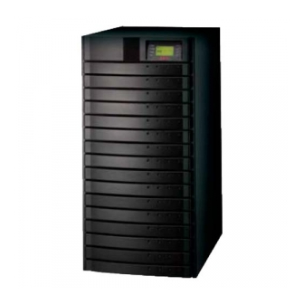
External View Front and Rear View of PROTECT 1.M (chassis) LED indicators System On/Off LC display Communication port Keys for UPS menu Communication module navigation UPS modules PROTECT 1.040 Slot cover caps with intake air channelling Front view with slot covers mounted Front view with slot covers removed... -
Page 24: Front/Rear And 3D View Protect 1.040 (Module)
Front/Rear and 3D View PROTECT 1.040 (UPS module) Handles with latching for easy removal or insertion of a PROTECT 1.040 UPS module Fans Front view Fans RS232 Blade-connect male Rear view Orientation markings for optimum displacement of the centre of gravity 3D view when holding a PROTECT 1.040 UPS module... -
Page 25: Front And Rear View (Communication Module)
Front and Rear View (communication module) Co nnec tor Blade-connect REAR VIEW Rear view Ha nd le Handle Communication port c om m unic a tion p ort for connecting the LC display SIDE VIEW FRONT VIEW Front view 3D view Front View of LCD Panel Com m unic atio n Line LCD connection cable... -
Page 26: Display Panel
Display Panel 1. "Normal": The green LED lights when the UPS is supplying the loads with voltage via the inverters (normal operation). 2. "On Battery": The yellow LED lights when the UPS is supplying power from the battery. 3. "Bypass": The yellow LED lights when the UPS is supplying the loads with mains voltage from public utility's mains. -
Page 27: Installation
AEG Power Solutions. 4. Connection diagram: The PROTECT 1.M has two input modes: A single-phase input and a three- phase input. The PROTECT 1.M detects the input mode and selects the corresponding operating mode automatically. - Page 28 b. Connection with three-phase input Note: If using three-phase mains connection, make sure the phase sequence is correct. The UPS cannot start up if the phase sequence is wrong, and an alarm will sound. At the same time, "Phase sequence error" appears on the LC display.
- Page 29 5. Connection cross-sections and fuse protection...
- Page 30 If you are using fuse load break switch for mains fusing, please select miniature circuit breakers with "D" characteristic. Route wires individually to guarantee reliable strain relief. Preferably use special rubber-insulated wire NSGAÖU or NSGAFÖU, NYY or Radox 4GKW-AX.
-
Page 31: Set-Up And Installation Of The Modules
Set-up and Installation of the Modules To set up the unit, position it in its installation location and use a spanner to turn the height- adjustable feet until they reach the floor. The feet are located at the four corners of the baseplate. Locking foot Bra ke pad Push the communication module into the top left-... - Page 32 Hold the UPS module firmly at the sides when pushing it in. Your thumbs should make contact with the orientation marks on the UPS module (see illustration below). Install the slot cover caps: Insert the slot cover caps from bottom to top over each individual slot. To ensure optimum cooling of the individual UPS modules, continuous operation is only permitted with the slot cover caps in place.
-
Page 33: Adding/Removing Modules
Adding/Removing Modules Active Redundancy n+x technology is one of the most reliable configurations. "n" represents the minimum number of PROTECT 1.040 UPS modules that requires the total power; "x" represents the number of redundant PROTECT 1.040 UPS modules, i.e. the number of fault-tolerant modules that the system can handle at the same time. -
Page 34: Basic Procedure For Installing A Protect 1.040 Ups Module
7.2.1 Basic procedure for installing a PROTECT 1.040 UPS module 1. Remove the slot cover cap from the rack in which the UPS module is going to be installed. 2. Grip the UPS module at the sides with both hands. The black dots on the top of the UPS module serve as orientation marks for where to position your thumbs in order to have the centre of gravity in the optimum position. -
Page 35: Operating And Maintenance
Operating and Maintenance Operation Make sure that the phase sequence is correct if you are using a three-phase mains connection (L1, L2, L3). If you are using a single-phase mains connection, make sure that phase L1 has been selected and correctly connected to the UPS. - Page 36 3) Press ESC 4) Press ▼ for the following information LOAD: BATT: 137 OUTPUT PARAMETER I / P VOLT: 232 232 231 O / P VOLT: 0 VOLT: 0V O / P FREQ: 0.0Hz CURR: 0A STATUS: NO OUTPUT FREQ: 0.0Hz Note: When the mains is connected for the first time, the UPS does not output any voltage (Figs.
-
Page 37: Start-Up
8.1.1 Start-up 1) Switch on 2) Press the 3) Press the ↵ / Return key ▼ key CONFIRM TURN UPS ON UPS ON NO, CANCEL SETUP YES, CONFIRM INQUIRE 4) Once again, press the ↵ / Return key LOAD: BATT: 136 I / P VOLT: 232 232 231 UPS IS TURNING ON O / P VOLT: 230... -
Page 38: Inquiries
3) Switch-off option 1: 4) Switch-off option 2: Load supply via bypass Load supply directly off "SWITCH TO BYPASS" "TURN OFF OUTPUT" CONFIRM CONFIRM SWITCH TO BYPASS WARNING: OUTPUT OFF NO, CANCEL NO, CANCEL YES, CONFIRM YES, CONFIRM 5) Select "YES, CONFIRM" and press the ↵... -
Page 39: Setup
3) Press the ↵ / Return key at the "PHONE" item, for example RETAILER PHONE: X X X X X X X X X X X X X X X X X X X X X X X X Setup 8.1.4 (press ESC to exit the aforementioned menus) The user can enter the User Setup menu by entering the... - Page 40 5) Select SETUP, 6) E.g. if the number of e.g. REDUNDAN and redundant modules is 0, … press ↵ / Return SETUP REDUNDANCE WARNING: TOTAL NUM: 3 CURRENT SETTING IS NO REDUNDANCY, OK? REDUN NUM: 1 MAX POWER CURRENT SETTING: 8kVA/5.6kW The redundancy setup applies after the Setup menu is exited, i.e.
-
Page 41: Maintenance
Maintenance Maintenance of the UPS and battery replacement should be performed by well trained expert personnel. Batteries that have not been used for some time must be charged up every three months at normal ambient temperature and every two months if the ambient temperature is high. -
Page 42: Shutdown And Ups Management Software
Shutdown and UPS Management Software The "CompuWatch" software specially developed for these purposes by AEG continuously checks the mains supply and the UPS status. In conjunction with the "intelligent" UPS, this guarantees the availability of the EDP components as well as the data security. -
Page 43: Communication Interfaces
9 Communication Interfaces The PROTECT 1.M has RS232 and RS485 interfaces as well as an expansion slot: As external connections, it is possible to use either an AS400 card (optional) or an SNMP/ SNMP PRO card (optional) for the expansion slot. 1. -
Page 44: Troubleshooting And Fault Rectification
Software status of CompuWatch or Download the latest software / not detect the PROTECT 1.M >> firmware of SNMP(pro) card outmoded; firmware from the AEG homepage. No communication error in computer configuration Check the communication cable. The LC display does not display... -
Page 45: Reference Table For The Display And Ups Operating
Reference Table for the Display and UPS Operating Problems Normal operation 11.1 Operating LED indications Warning signal LC displays Notes status / Operating problems Mains in tolerance None range Mains not in "utility power 1 acoustic signal tolerance, i.e. is abnormal" every 4s batt. -
Page 46: Warning Signal If Battery System Not Connected
Warning Signal if Battery System Not 11.4 Connected, e.g. battery fuse failure Operating LED indications Warning signal LC displays Notes status / Operating problems "UPS is not Check battery Bypass 1 acoustic signal connected to system; poss. mode every 4 s the battery"... -
Page 47: Overload Protection
Overload Protection 11.6 Operating LED indications Warning LC displays Notes status / signal Operating problems 1 acoustic Overload in "Output signal Reduce the load normal operation overload" UPS warning every 2 s Continuous "Output Overload in warning overload"Alarm Reduce the load normal operation >... -
Page 48: Minimum Number Of Battery Packs
Minimum Number of Battery Packs Batteries with different capacity have specific charging and discharging characteristics. Standard configurations have been defined in order to make optimum use of the service life. The hatched part shows the permitted configurations. Configuration table for battery cabinet systems equipped with 24 or 28 Ah battery blocks Power 24/28 Ah x 1 24/28 Ah x 2 24/28 Ah x 3 24/28 Ah x 4 24/28 Ah x 5 24/28 Ah x 6... - Page 49 The following tables show the achievable standby times according to the UPS expansion level and capacity utilisation as well as depending on the optional battery cabinet units that are connected ex-works:...
-
Page 51: List Of Terms
List of terms Technical terminology 13.1 DC/DC booster Circuit technology for increasing a DC voltage to a higher voltage level Static Bypass Switch Appliance protection Term from overvoltage technology Classic mains overvoltage protection consists of lighting surge arrester (class B), overvoltage protection (class C) and, finally, the so-called appliance protection (class D) - see also the http://www.phoenixcontact.com... - Page 52 Notes...
- Page 53 Notes...
- Page 54 Notes...
- Page 55 Notes...
- Page 56 Guarantee Certificate Type: …….……………….…............Unit number: ….………….…..……………........ Date of purchase:………………...……………………..Dealer stamp / signature Errors and changes excepted. AEG Power Solutions GmbH Emil-Siepmann-Straße 32 59581 Warstein-Belecke Germany Operating instructions BAL 8000015763_02 EN...
Need help?
Do you have a question about the Protect 1. M and is the answer not in the manual?
Questions and answers