
Related Manuals for Nexcom NDiS 127


Summary of Contents for Nexcom NDiS 127
- Page 1 NEXCOM International Co., Ltd. Multi-Media Solutions Digital Signage Platform NDiS 127 User Manual NEXCOM International Co., Ltd. www.nexcom.com Published May 2012...
-
Page 2: Table Of Contents
USB Port Header .................16 COM Header ..................17 Chapter 2: Jumpers and Connectors SPDIF Header ..................17 Before You Begin ...................5 Mini-PCIe ...................18 Precautions ....................6 Jumper Settings ..................7 Copyright © 2012 NEXCOM International Co., Ltd. All Rights Reserved. NDiS 127 User Manual... - Page 3 Super IO Configuration ...............44 PC Health Status .................45 Magic Control ..................46 Chipset ....................47 North Bridge Configuration ..............48 South Bridge Configuration ..............49 AMD Power Express Configuration .............50 Copyright © 2012 NEXCOM International Co., Ltd. All Rights Reserved. NDiS 127 User Manual...
-
Page 4: Preface
Any implied warranties of merchantability or fitness for any particular purpose is also disclaimed. Acknowledgements NDiS 127 is a trademark of NEXCOM International Co., Ltd. All other prod- uct names mentioned herein are registered trademarks of their respective owners. - Page 5 0.1% or 1,000ppm, and Polybrominated diphenyl Ethers (PBDE) < 0.1% or 1,000ppm. In order to meet the RoHS compliant directives, NEXCOM has established an engineering and manufacturing task force in to implement the introduction of green products. The task force will ensure that we follow the standard...
- Page 6 ? Replace with 3rd party products if needed. the RMA number apply process. ? If RMA goods can not be repaired, NEXCOM will return it to the cus- tomer without any charge. ? Customers can send back the faulty products with or without acces- sories (manuals, cable, etc.) and any components from the card, such as...
-
Page 7: Safety Information
There is a danger of explosion if battery is incorrectly replaced. Replace only with the same or equivalent type recommended by the manufactur- er. Discard used batteries according to the manufacturer’s instructions. Copyright © 2012 NEXCOM International Co., Ltd. All Rights Reserved. NDiS 127 User Manual... -
Page 8: Safety Precautions
11. All cautions and warnings on the equipment should be noted. 19. The computer is provided with CD drives that comply with the ap- propriate safety standards including IEC 60825. viii Copyright © 2012 NEXCOM International Co., Ltd. All Rights Reserved. NDiS 127 User Manual... - Page 9 Technical Support and Assistance Conventions Used in this Manual Warning: Information about certain situations, which if not 1. For the most updated information of NEXCOM products, visit NEX- observed, can cause personal injury. This will prevent injury to COM’s website at www.nexcom.com.
- Page 10 Z.I. des Amandiers, 17, Rue des entrepreneurs Tel: +44-1908-267121 78420 Carrières sur Seine, France Fax: +44-1908-262042 Tel: +33 (0)1 71 51 10 20 http://www.nexcom.eu Fax: +33 (0)1 71 51 10 21 http://www.nexcom.eu Copyright © 2012 NEXCOM International Co., Ltd. All Rights Reserved. NDiS 127 User Manual...
- Page 11 Fax: +86-25-8315-3489 http://www.nexcom.cn China-Shenzhen Office Western Room 708, Block 210, Tairan Industry & Trading Place, Futian Area, Shenzhen, China 518040 TEL: +86-755-833 27203 FAX: +86-755-833 27213 http://www.nexcom.cn Copyright © 2012 NEXCOM International Co., Ltd. All Rights Reserved. NDiS 127 User Manual...
-
Page 12: Package Contents
Preface aCkage ontents Before continuing, verify that the NDiS 127 package that you received is complete. Your NDiS 127 package should have all the items listed in the following table. Item Name Specification 602DCD0431X00 NDiS127 CD DRIVER MANUAL VER:1.0 6012200053X00... -
Page 13: Ordering Information
The following provides ordering information for NDiS 127. • NDiS 127 (P/N: 10W00012700X0) AMD G-series Dual Core processor T56N 1.65GHz AMD Radeon™ HD6320 GPU in processor AMD A55E Controller Hub xiii Copyright © 2012 NEXCOM International Co., Ltd. All Rights Reserved. NDiS 127 User Manual... -
Page 14: Chapter 1: Product Introduction
• NDiS 127 is housed in a maintenance-free fanless chassis with compact size. NDiS 127 is designed to fulfill small form factors, low cost, high reliability and low power requirement in digital signage application. Copyright © 2012 NEXCOM International Co., Ltd. All Rights Reserved. -
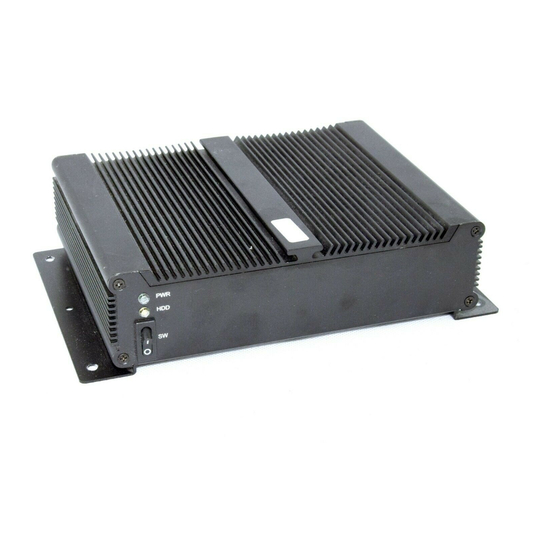
Page 15: Physical Features
Chapter 1: Product Introduction Physical Features Front panel Rear panel Power Line Out HDMI LAN MIC In DC-in Power Button Copyright © 2012 NEXCOM International Co., Ltd. All Rights Reserved. NDiS 127 User Manual... -
Page 16: System Specifications
• CE approval • 1 x RJ45 Gigabit LAN connector with LED • FCC Class A • 1 x Line-out/ 1x Mic-in • 1 x HDMI Copyright © 2012 NEXCOM International Co., Ltd. All Rights Reserved. NDiS 127 User Manual... -
Page 17: Mechanical Dimensions
Chapter 1: Product Introduction Mechanical Dimensions 215.4 Copyright © 2012 NEXCOM International Co., Ltd. All Rights Reserved. NDiS 127 User Manual... -
Page 18: Chapter 2: Jumpers And Connectors
This chapter describes how to set the jumpers on the motherboard. Note Before working on internal components, make sure that the poweris off. that the following procedures are generic for all NDiS 127 series. Ground yourself before touching any internal components, by touching a metal object. -
Page 19: Precautions
Leave all components inside the static-proof packaging that they shipped with until they are ready for installation. ▪ Use correct screws and do not over tighten screws. Copyright © 2012 NEXCOM International Co., Ltd. All Rights Reserved. NDiS 127 User Manual... -
Page 20: Jumper Settings
(on) and open (off). Two-Pin Jumpers: Open (Left) and Short (Right) Three-Pin Jumpers: Pins 1 and 2 Are Short Copyright © 2012 NEXCOM International Co., Ltd. All Rights Reserved. NDiS 127 User Manual... -
Page 21: Locations Of The Jumpers And Connectors
Chapter 2: Jumpers and Connectors Locations of the Jumpers and Connectors NDiB 127 The figure on the right is the NDiB 127 motherboard which is the motherboard used in the NDiS 127 system. It shows the locations of the jumpers and connectors. F_USB F_AUDIO1... -
Page 22: External Connectors Pin Definitions
And if you use others like 19V, it will damage the boards. TMDS Clock Shield TMDS Clock– DDC/CEC/HEC Ground Power (VCC5) Hot Plug Detect Copyright © 2012 NEXCOM International Co., Ltd. All Rights Reserved. NDiS 127 User Manual... -
Page 23: Vga Connector
Definition Definition Definition MDI3- GREEN MDI3+ MDI2- BLUE MDI2+ MDI1- MDI1+ MDI0- MDI0+ TCTG VCC (VCC5) V3_3M LED_ACT# DDC Data LED_1000# LED_100# HSYNC VSYNC DDC Clock Copyright © 2012 NEXCOM International Co., Ltd. All Rights Reserved. NDiS 127 User Manual... -
Page 24: Led Hdd/Pwr
Chapter 2: Jumpers and Connectors LED HDD/PWR Audio Jack Audio LED No. Function Description Connector Function Description Power LED (Green) Green Line Out HDD LED (Yellow) Pink Mic-IN Copyright © 2012 NEXCOM International Co., Ltd. All Rights Reserved. NDiS 127 User Manual... -
Page 25: Usb Port
Chapter 2: Jumpers and Connectors USB Port RS232 Port USB1 / USB2 Standard DB9 Connector Definition Definition Definition Definition VCC (VCC5) DATA1- DATA1+ VCC (VCC5) DATA- DATA+ Copyright © 2012 NEXCOM International Co., Ltd. All Rights Reserved. NDiS 127 User Manual... -
Page 26: Internal Connectors Pin Definitions
This section provides descriptions, illustrations and pin definitions of the internal connectors. Clear CMOS Selection CLR_CMOS Definition Definition Jumper Status Normal Operation (default) Clear CMOS VCC5 VCC5 VCC5 Copyright © 2012 NEXCOM International Co., Ltd. All Rights Reserved. NDiS 127 User Manual... -
Page 27: Front Panel Audio Pin Header
Front Panel LED / Switch Pin Header F_Audio F_Panel Definition Definition Definition Definition MIC IN_L AGND HDD_LED+ PWR_LED+ MIC2_R HDD_LED- PWR_LED- OUT2_R MIC_JD RESET PWR_ON J_SEN RESET PWR_ON OUT_L OUT_JD Copyright © 2012 NEXCOM International Co., Ltd. All Rights Reserved. NDiS 127 User Manual... -
Page 28: Vga Pin Header
Please well know about it, VGA cable have 1 Pin with Red colour, It is Pin 1. VGA cable Pin1 must connect to motherboard Pin1, if you connector wrong, it will damage or burn the VGA Cable. Copyright © 2012 NEXCOM International Co., Ltd. All Rights Reserved. NDiS 127 User Manual... -
Page 29: Fan Header
Chapter 2: Jumpers and Connectors FAN Header USB Port Header F_USB SYS_FAN Definition Definition Definition VGA_ERD DDC_DATA H-SYNC +12V VGA_GREEN V-SYNC SIO_SYSFAN_SIO_TACH DDC_CLK VGA_BLUE CPU_FAN Definition +12V SIO_CPUFAN_SIO_PWM FAN Control Copyright © 2012 NEXCOM International Co., Ltd. All Rights Reserved. NDiS 127 User Manual... -
Page 30: Com Header
Chapter 2: Jumpers and Connectors COM Header SPDIF Header SPDIF COM1 / COM2 Definition Definition Definition SPDIF_OUT SPDIF_IN Copyright © 2012 NEXCOM International Co., Ltd. All Rights Reserved. NDiS 127 User Manual... -
Page 31: Mini-Pcie
Definition WAKE# +V3.3A_MIN +V1.5S_MIN SMB_CLK +V1.5S_MIN PETn0 SMB_DATA CLKREQ# PETp0 USB_D- REFCLK- USB_D+ REFCLK+ +V3.3A_MIN +V3.3A_MIN LED_WWAN# LED_WLAN# DISABLE# LED_WPAN# PERST# +V1.5S_MIN PERn0 +V3.3A_MIN PERp0 +V3.3A_MIN Copyright © 2012 NEXCOM International Co., Ltd. All Rights Reserved. NDiS 127 User Manual... -
Page 32: Chapter 3: System Setup
1. The screws on the bottom of cover are used to secure the cover to the chassis. Remove these screws and put them in a safe place for later use. Copyright © 2012 NEXCOM International Co., Ltd. All Rights Reserved. NDiS 127 User Manual... -
Page 33: Installing A So-Dimm
1. Loosen the mounting screws and remove the HDD bracket. Locate for the SO-DIMM socket on the board. SO-DIMM Mounting Sockets Screws Ejector Tab Copyright © 2012 NEXCOM International Co., Ltd. All Rights Reserved. NDiS 127 User Manual... - Page 34 The ejector tabs at the ends of the socket will automatically snap into the locked position to hold the module in place. Notch Copyright © 2012 NEXCOM International Co., Ltd. All Rights Reserved. NDiS 127 User Manual...
- Page 35 5. Align the mounting holes of the HDD bracket with the mounting studs on the board then use the provided mounting screws to secure the HDD bracket in place. Copyright © 2012 NEXCOM International Co., Ltd. All Rights Reserved. NDiS 127 User Manual...
-
Page 36: Installing A Sata Hard Drive
1. The drive bracket included in the chassis is used to hold a SATA hard mounting holes on the drive bracket. drive. Disassembly HDD bracket from system to install SATA Hard Drive. Mounting Screw Holes Copyright © 2012 NEXCOM International Co., Ltd. All Rights Reserved. NDiS 127 User Manual... - Page 37 3. Locate for the SATA connector and the SATA power connector on the 4. Use the provided screws to secure the SATA drive in place. SATA drive. SATA Data Connector SATA Power Connector Mounting Screw Copyright © 2012 NEXCOM International Co., Ltd. All Rights Reserved. NDiS 127 User Manual...
-
Page 38: Installing A Wireless Lan Module
1. Remove bottom cover and locate for the Half Mini PCI Express slot on the module completely disappears inside the slot. board. Mounting Screw Mini PCI Express Slot Wireless LAN Module Copyright © 2012 NEXCOM International Co., Ltd. All Rights Reserved. NDiS 127 User Manual... - Page 39 3. Push the module down then secure it with mounting screws. 4. Attach one end of the RF cable onto the WiFi module. RF Cable Mounting Screw WiFi RF Cable Antenna Attached to the Jack Module Copyright © 2012 NEXCOM International Co., Ltd. All Rights Reserved. NDiS 127 User Manual...
- Page 40 6. Now mount the WiFi antenna jack to the WiFi antenna hole located at the rear panel of the chassis then tighten the rings. Ring2 Ring1 Copyright © 2012 NEXCOM International Co., Ltd. All Rights Reserved. NDiS 127 User Manual...
- Page 41 7. Align the screw holes of the cover with the screw holes on the bottom 8. Now connect an external antenna to the WiFi antenna jack. plate then use the provided mounting screws to secure the cover in place. Antenna Copyright © 2012 NEXCOM International Co., Ltd. All Rights Reserved. NDiS 127 User Manual...
-
Page 42: Installing A Tv Tuner Module
1. Remove bottom cover and locate for the Mini PCI Express slot on the module completely disappears inside the slot. board. Mounting Screw Mini PCI Express Slot Copyright © 2012 NEXCOM International Co., Ltd. All Rights Reserved. NDiS 127 User Manual... - Page 43 4. Attach one end of the RF cable onto the TV Tuner module. RF Cable RF Cable Attached to the Module WiFi Mounting Screw Antenna Jack Copyright © 2012 NEXCOM International Co., Ltd. All Rights Reserved. NDiS 127 User Manual...
- Page 44 6. Now mount the TV Tuner antenna jack to the TV Tuner antenna hole located at the rear panel of the chassis then tighten the rings. Ring2 Ring1 Copyright © 2012 NEXCOM International Co., Ltd. All Rights Reserved. NDiS 127 User Manual...
- Page 45 8. Now connect an external antenna to the TV Tuner antenna jack. plate then use the provided mounting screws to secure the cover in place. Antenna Copyright © 2012 NEXCOM International Co., Ltd. All Rights Reserved. NDiS 127 User Manual...
-
Page 46: Installing Wallmount Brackets
Mount the system on the wall by fastening screws through the brackets mounting holes. Fasten screws to mount the system to the wall Copyright © 2012 NEXCOM International Co., Ltd. All Rights Reserved. NDiS 127 User Manual... -
Page 47: Chapter 4: Bios Setup
This chapter describes how to use the BIOS setup program for NDiS 127. The settings made in the setup program affect how the computer per- The BIOS screens provided in this chapter are for reference only and may forms. -
Page 48: Default Configuration
When “u“ appears on the left of a particular field, it indicates that a submenu which contains additional options are available for that field. To display the submenu, move the highlight to that field and press <Enter>. Copyright © 2012 NEXCOM International Co., Ltd. All Rights Reserved. NDiS 127 User Manual... -
Page 49: Bios Setup Utility
Select Item System Date [Tue 10/05/2010] Change Opt. General Help Access Level Administrator Previous Values Save and Exit Exit Version 2.10.1208 Copyright (C) 2010 American Megatrends, Inc. Copyright © 2012 NEXCOM International Co., Ltd. All Rights Reserved. NDiS 127 User Manual... -
Page 50: Advanced
Save and Exit CPU. Exit Version 2.10.1208 Copyright (C) 2010 American Megatrends, Inc. USB Configuration This section is used to enable or disable the USB controller. Copyright © 2012 NEXCOM International Co., Ltd. All Rights Reserved. NDiS 127 User Manual... - Page 51 This section is used to configure the I/O functions supported by the on- board Super I/O chip. H/W Monitor This section is used to configure the hardware monitoring events such as temperature, fan speed and voltages. Copyright © 2012 NEXCOM International Co., Ltd. All Rights Reserved. NDiS 127 User Manual...
-
Page 52: Pci Subsystem Setting
Value to be programmed into PCI latency Timer Register. • Extended Synch • VGA Palette Snoop Allows generation of extend synchronization patterns. This section is used to enable or disable VGA Palette Registers Snooping. Copyright © 2012 NEXCOM International Co., Ltd. All Rights Reserved. NDiS 127 User Manual... -
Page 53: Acpi Settings
This section is used to enable or disable lock of legacy resources. Previous Values Save and Exit Exit S3 Video Repost Version 2.10.1208 Copyright (C) 2010 American Megatrends, Inc. Enable or Disable S3 Video Repost. Copyright © 2012 NEXCOM International Co., Ltd. All Rights Reserved. NDiS 127 User Manual... -
Page 54: S5 Rtc Wake Settings
← → Select Screen ↑↓ Select Item Change Opt. General Help Previous Values Save and Exit Exit Version 2.10.1208 Copyright (C) 2010 American Megatrends, Inc. Copyright © 2012 NEXCOM International Co., Ltd. All Rights Reserved. NDiS 127 User Manual... -
Page 55: Cpu Configuration
This section is used to enable or disable the CPU virtualization function. C6 Mode This section is used to enable or disable the C6. Node 0 Information View memory information related to node 0. Copyright © 2012 NEXCOM International Co., Ltd. All Rights Reserved. NDiS 127 User Manual... -
Page 56: Usb Configuration
Maximum time the device will take before it properly reports it self to the Host Controller. ‘Auto’ uses default value; for a Root port it is 100 ms, for a Hub port the delay is taken form Hub descriptor. Copyright © 2012 NEXCOM International Co., Ltd. All Rights Reserved. NDiS 127 User Manual... -
Page 57: Super Io Configuration
Save and Exit Exit Version 2.10.1208 Copyright (C) 2010 American Megatrends, Inc. Serial Port 0 / 1 Configuration Selects the IO/IRQ setting of the I/O devices. Copyright © 2012 NEXCOM International Co., Ltd. All Rights Reserved. NDiS 127 User Manual... -
Page 58: Pc Health Status
The system voltage is monitored. ← → Select Screen ↑↓ Select Item Change Opt. General Help Previous Values Save and Exit Exit Version 2.10.1208 Copyright (C) 2010 American Megatrends, Inc. Copyright © 2012 NEXCOM International Co., Ltd. All Rights Reserved. NDiS 127 User Manual... -
Page 59: Magic Control
During Enabled, Choose the Date, Hour, Minute, and Second. SATA Port Onboard LAN Controller Enable or disable the SATA Port function. This section is used to enable or disable the Watch Dog Function. Copyright © 2012 NEXCOM International Co., Ltd. All Rights Reserved. NDiS 127 User Manual... -
Page 60: Chipset
Select Screen ↑↓ Select Item Express configuration parameters. Change Opt. General Help Previous Values Save and Exit Exit Version 2.10.1208 Copyright (C) 2010 American Megatrends, Inc. Copyright © 2012 NEXCOM International Co., Ltd. All Rights Reserved. NDiS 127 User Manual... -
Page 61: North Bridge Configuration
Version 2.10.1208 Copyright (C) 2010 American Megatrends, Inc. • Integrated Graphics This Option Allows User to enable Integrate Graphic controller. • Bank Interleaving This Option Allows User to enable Bank Interleaving function. Copyright © 2012 NEXCOM International Co., Ltd. All Rights Reserved. NDiS 127 User Manual... -
Page 62: South Bridge Configuration
Previous Values This Option Allows User to enable USB deivce wkeup from S3 or S4. Save and Exit Exit Version 2.10.1208 Copyright (C) 2010 American Megatrends, Inc. Copyright © 2012 NEXCOM International Co., Ltd. All Rights Reserved. NDiS 127 User Manual... -
Page 63: Amd Power Express Configuration
(if supported) such as PowrXpress: Discrete Gfx primary Integrated Gfx primary due to inter dependency the primary Display menu will not be available if any on e of these are enabled. Copyright © 2012 NEXCOM International Co., Ltd. All Rights Reserved. NDiS 127 User Manual... -
Page 64: Boot
NumLock on wherein the function of the numeric keypad is the number keys. When set to Off, the function of the numeric keypad is the arrow keys. Copyright © 2012 NEXCOM International Co., Ltd. All Rights Reserved. NDiS 127 User Manual... -
Page 65: Security
3. Press <Enter> to confirm the new password. 4. When the Password Installed dialog box appears, select OK. To change the password, repeat the same steps above. Copyright © 2012 NEXCOM International Co., Ltd. All Rights Reserved. NDiS 127 User Manual... -
Page 66: Exit
Restore / Load the default values from the BIOS ROM. Launch EFI Shell from filesystem device Attempts to launch EFI Shell application (Shellx64.efi)from one of the avail- able file system devices. Copyright © 2012 NEXCOM International Co., Ltd. All Rights Reserved. NDiS 127 User Manual... - Page 67 Introduction Example Programs NDiS 127 features a watchdog timer that resets the CPU or generates #define INDEXP 0x2e an interrupt if the processor stops operating for any reason. This #define DATAP 0x2f feature ensures system reliability in industrial standalone or unmanned //Super I/O Watchdog environments.
- Page 68 SIOWTD_Enable(short time,short unit) /*unit=0:second,=1:minutes */ WRITEREG(0x73,time) //t timeout value //end programming watchdog if(time<1 || time>255) return -1; ENDPROG if(unit<0 || unit>1) return -1; return 0; //start programming watchdog Copyright © 2012 NEXCOM International Co., Ltd. All Rights Reserved. NDiS 127 User Manual...
Need help?
Do you have a question about the NDiS 127 and is the answer not in the manual?
Questions and answers