
Related Manuals for Nexcom NDiS M535


Summary of Contents for Nexcom NDiS M535
- Page 1 NEXCOM International Co., Ltd. Multi-Media Solutions Digital Signage Platform NDiS M535 User Manual NEXCOM International Co., Ltd. www.nexcom.com Published May 2016...
-
Page 2: Table Of Contents
Internal Connectors ................16 Rear Panel ...................2 SATA Connector (7-pin and 15-pin) ..........16 Hardware Specifications ................3 RTC Battery Connector ..............16 Mechanical Dimensions ................4 Port 80 Connector .................17 Copyright © 2016 NEXCOM International Co., Ltd. All Rights Reserved. NDiS M535 User Manual... - Page 3 Entering Setup ..................29 Legends ....................29 BIOS Setup Utility ..................31 Main ....................31 Advanced ..................32 Security .....................39 Boot ....................39 Save & Exit ..................40 Appendix A: Watchdog Timer .......41 Copyright © 2016 NEXCOM International Co., Ltd. All Rights Reserved. NDiS M535 User Manual...
-
Page 4: Preface
No describes how to keep the system CE compliant. part of this manual may be reproduced, copied, translated or transmitted in any form or by any means without the prior written consent from NEXCOM Declaration of Conformity International Co., Ltd. -
Page 5: Rohs Compliance
(Cr6+) < 0.1% or 1,000ppm, Polybrominated biphenyls (PBB) < 0.1% or 1,000ppm, and Polybrominated diphenyl Ethers (PBDE) < 0.1% or 1,000ppm. In order to meet the RoHS compliant directives, NEXCOM has established an engineering and manufacturing task force to implement the introduction of green products. -
Page 6: Warranty And Rma
(manuals, cable, etc.) and any components from the card, such as CPU and RAM. If the components were suspected as part of the problems, ▪ If RMA goods can not be repaired, NEXCOM will return it to the customer please note clearly which components are included. Otherwise, NEXCOM without any charge. - Page 7 ESD workstation. If no such station is available, you can provide some ESD protection by wearing an antistatic wrist strap and attaching it to a metal part of the computer chassis. Copyright © 2016 NEXCOM International Co., Ltd. All Rights Reserved. NDiS M535 User Manual...
-
Page 8: Safety Information
There is a danger of explosion if battery is incorrectly replaced. Replace only with the same or equivalent type recommended by the manufacturer. Discard used batteries according to the manufacturer’s instructions. viii Copyright © 2016 NEXCOM International Co., Ltd. All Rights Reserved. NDiS M535 User Manual... -
Page 9: Safety Precautions
RECOMMENDED BY THE MANUFACTURER. DISCARD USED BATTERIES ACCORDING TO THE MANUFACTURER’S INSTRUCTIONS. 10. All cautions and warnings on the equipment should be noted. Copyright © 2016 NEXCOM International Co., Ltd. All Rights Reserved. NDiS M535 User Manual... -
Page 10: Technical Support And Assistance
Preface Technical Support and Assistance Conventions Used in this Manual 1. For the most updated information of NEXCOM products, visit NEXCOM’s Warning: website at www.nexcom.com. Information about certain situations, which if not observed, can cause personal injury. This will prevent injury to yourself 2. -
Page 11: Global Service Contact Information
13F, No.920, Chung-Cheng Rd., ZhongHe District, Beijing, 100094, China New Taipei City, 23586, Taiwan, R.O.C. Tel: +86-10-5704-2680 Tel: +886-2-8226-7796 Fax: +86-10-5704-2681 Fax: +886-2-8226-7792 Email: sales@nexcom.cn Email: sales@nexcom.com.tw www.nexcom.cn www.nexcom.com.tw Copyright © 2016 NEXCOM International Co., Ltd. All Rights Reserved. NDiS M535 User Manual... - Page 12 Hui Yin Ming Zun Building Room 1108, Building No. 11, 599 Yunling Road, Putuo District, Shanghai, 200062, China Tel: +86-21-6125-8282 Fax: +86-21-6125-8281 Email: frankyang@nexcom.cn www.nexcom.cn Copyright © 2016 NEXCOM International Co., Ltd. All Rights Reserved. NDiS M535 User Manual...
-
Page 13: Package Contents
Preface Package Contents Before continuing, verify that the NDiS M535 package that you received is complete. Your package should have all the items listed in the following table. Item Part Number Name Description 50311F0112X00 (H)Flat Head Screw Long Fei: F3 x 4iso... -
Page 14: Ordering Information
Preface Ordering Information The following below provides ordering information for NDiS M535. NDiS M535 (P/N: 10W00M53500X0) 6th generation Intel Core™ i5-6440EQ BGA type processor OPS, ® Intel ® QM170 chipset NDiS M535-6820EQ (P/N: 10W00M53501X0) 6th generation Intel Core™ i7-6820EQ BGA type processor OPS, ®... -
Page 15: Chapter 1: Product Introduction
▪ WWAN/WLAN/TV Tuner support ▪ DirectX ® 12 support NDiS M535 is an OPS-compliant media player powered by 6th generation Intel ® Core™ processors. Following open pluggable standard, NDiS M535 can perfectly fit into a myriad of OPS-panels and is compact in size. Yet, NDiS M535 has high scalability, allowing for easy storage capacity expansion through pluggable 2.5”... -
Page 16: Physical Features
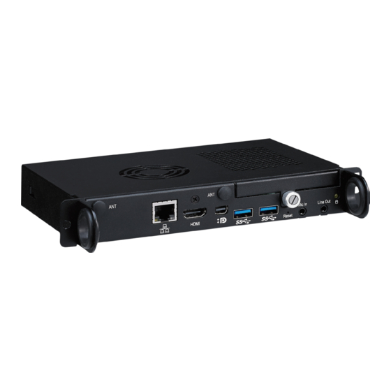
Chapter 1: Product Introduction Physical Features Front Panel Rear Panel Antenna Antenna HDD LED HDD Slot Mic-in Line-out Power HDMI mDP USB 3.0 JAE TX25 80Pin Reset Button Button Copyright © 2016 NEXCOM International Co., Ltd. All Rights Reserved. NDiS M535 User Manual... -
Page 17: Hardware Specifications
▪ Windows 7 (32-bit/64-bit) / Windows 8.1 (64-bit)/ Windows 10 (64-bit) I/O Interface-Rear ▪ 1x TMDS (HDMI) ▪ 1x USB 3.0 ▪ 2x USB 2.0 ▪ 1x UART (TX/RX) Copyright © 2016 NEXCOM International Co., Ltd. All Rights Reserved. NDiS M535 User Manual... -
Page 18: Mechanical Dimensions
Chapter 1: Product Introduction Mechanical Dimensions 180.00 200.00 30.00 Copyright © 2016 NEXCOM International Co., Ltd. All Rights Reserved. NDiS M535 User Manual... -
Page 19: Chapter 2: Jumpers And Connectors
Static electricity can damage many of the electronic ▪ Use correct screws and do not over tighten screws. components. Humid environments tend to have less static electricity than Copyright © 2016 NEXCOM International Co., Ltd. All Rights Reserved. NDiS M535 User Manual... -
Page 20: Locations Of The Jumpers And Connectors For Ndib M535
Locations of the Jumpers and Connectors for NDiB M535 NDiB M535 The figure below is the top and bottom view of the NDiB M535 mainboard which is the mainboard used in NDiS M535. It shows the locations of the jumpers and connectors. Top View LED1 Copyright ©... -
Page 21: Bottom View
Chapter 2: Jumpers and Connectors Bottom View CN10 CN11 Copyright © 2016 NEXCOM International Co., Ltd. All Rights Reserved. NDiS M535 User Manual... -
Page 22: Jumper Settings
(on) and open (off). Two-Pin Jumpers: Open (Left) and Short (Right) Three-Pin Jumpers: Pins 1 and 2 are Short Copyright © 2016 NEXCOM International Co., Ltd. All Rights Reserved. NDiS M535 User Manual... -
Page 23: Jumpers
RTC Control Connector Connector type: 1x3 3-pin header, 2.54mm pitch Connector location: J3 Settings 1-2 On Normal 2-3 On Clear CMOS 1-2 On: default Definition RTC_RST#_PU RTC_RST# CLR_CMOS Copyright © 2016 NEXCOM International Co., Ltd. All Rights Reserved. NDiS M535 User Manual... -
Page 24: Connector Pin Definitions
Connector location: SW1 Connector location: CN5 Definition Definition Definition Definition PBT_PU MID3- PBT_PU MID3+ MID2- PWRLED_N PWRLED_P MID2+ MID1- MID1+ MID0- MID0+ LED+ LAN_ACTLED#_C LAN1_LED2P LAN1_LED3P Copyright © 2016 NEXCOM International Co., Ltd. All Rights Reserved. NDiS M535 User Manual... -
Page 25: Hdmi Port
TMDS DATA1+ LANE0_P CONFIG1 TMDS DATA1- LANE0_N CONFIG2 TMDS DATA0+ TMDS DATA0- TMDS CLOCK+ LANE1_P LANE3_P TMDS CLOCK- LANE1_P LANE3_N LANE2_P AUXP LANE2_N AUXN HOT PLUG DETECT Copyright © 2016 NEXCOM International Co., Ltd. All Rights Reserved. NDiS M535 User Manual... -
Page 26: Usb 3.0 Ports
LED Connector Connector type: USB 3.0 port, Type A Connector location: LED1 Connector location: CN6 and CN7 Definition Definition Definition VBUS POWER HD_LEDN SSRX- SSRX+ SSTX- SSTX+ Copyright © 2016 NEXCOM International Co., Ltd. All Rights Reserved. NDiS M535 User Manual... -
Page 27: Reset Button
Chapter 2: Jumpers and Connectors Reset Button Mic-in Connector Connector location: SW2 Connector type: 3.5mm TRS Connector location: CN11 Definition Definition Definition RST_BTN# MIC_IN_R MIC_IN_L Copyright © 2016 NEXCOM International Co., Ltd. All Rights Reserved. NDiS M535 User Manual... -
Page 28: Line-Out Connector
Chapter 2: Jumpers and Connectors Line-out Connector Connector type: 3.5mm TRS Connector location: CN10 Definition Definition LINE2_OUT_R_FB LINE2_OUT_L_FB Copyright © 2016 NEXCOM International Co., Ltd. All Rights Reserved. NDiS M535 User Manual... -
Page 29: Jae-Tx25 Connector
AZ_LINEOUT_R DDP_1P RSVD TMDS2- RSVD PB_DET DDP_0N TMDS2+ SYS_FAN PS_ON# DDP_0P UART_RXD PWR_STATUS DVI_DDC_DATA UART_TXD DDP_AUXN DVI_DDC_CLK DDP_AUXP DVI_HPD StdA_SSRX- DDP_HPD StdA_SSRX+ +12V~+19V TMDS_CLK- +12V~+19V StdA_SSTX- Copyright © 2016 NEXCOM International Co., Ltd. All Rights Reserved. NDiS M535 User Manual... -
Page 30: Internal Connectors
Connector type: 1x2 2-pin header JST, 1.25mm pitch Connector location: CN2 Connector location: J6 Definition Definition Definition Definition SATA_TXPO_C VBAT1 SATA_TXNO_C SATA_RXNO_C SATA_RXNO_C VCC5 VCC5 VCC5 SATA_V12 SATA_V12 SATA_V12 Copyright © 2016 NEXCOM International Co., Ltd. All Rights Reserved. NDiS M535 User Manual... -
Page 31: Port 80 Connector
Connector type: 1x10 10-pin header JST, 1.0mm pitch Connector location: CN9 Connector location: J2 Definition Definition Definition Definition VCC3 VCC3 UIM_PWR UIM_RST LPC_AD0 LPC_AD1 UIM_CLK UIM_DAT LPC_AD2 LPC_AD3 LPC_FRAME# LPC_CLK0 SIO_RST# Copyright © 2016 NEXCOM International Co., Ltd. All Rights Reserved. NDiS M535 User Manual... -
Page 32: Mini-Pcie Connector
SMB_CLK D15VS mPCIE_TX_N SMB_DATA CLKREQ# UIM_PWR mPCIE_TX_P UIM_DATA USB_IN MC_PCIE_CLK_N UIM_CLK USB_IP MC_PCIE_CLK_P UIM_RESET +3.3B_MINI UIM_VPP +3.3B_MINI LED_WLAN# MINICARD1_DIS# WLAN_RESET# D15VS mPCIE_RX_N +3.3B_MINI mPCIE_RX_P PRE-DEC +3.3B_MINI Copyright © 2016 NEXCOM International Co., Ltd. All Rights Reserved. NDiS M535 User Manual... -
Page 33: Chapter 3: System Setup
2. With the screws removed, lift up the cover and remove it from the chassis. chassis. Remove these screws and put them in a safe place for later use. Screw on the back Screws on the sides Copyright © 2016 NEXCOM International Co., Ltd. All Rights Reserved. NDiS M535 User Manual... -
Page 34: Installing A So-Dimm Memory Module
1. At the bottom of the system, loosen the screws on the bottom cover and on the side, then remove the cover from the chassis. Screw DIMM1 DIMM2 Copyright © 2016 NEXCOM International Co., Ltd. All Rights Reserved. NDiS M535 User Manual... - Page 35 The ejector tabs at the ends of the socket will automatically snap into module can be plugged into the socket in only one direction. the locked position to hold the module in place. Ejector Notch Copyright © 2016 NEXCOM International Co., Ltd. All Rights Reserved. NDiS M535 User Manual...
-
Page 36: Installing A 2.5" Ssd/Hdd Storage
Make sure the connector side of the HDD is facing outwards. 1. Remove the HDD cover located at the front panel by loosening the screw. Screw Screw Copyright © 2016 NEXCOM International Co., Ltd. All Rights Reserved. NDiS M535 User Manual... - Page 37 4. Stick the protective pad on the bottom of the HDD to prevent short 5. Place the HDD back into the slot, then tighten the screw to secure it. circuiting with the chassis. Copyright © 2016 NEXCOM International Co., Ltd. All Rights Reserved. NDiS M535 User Manual...
-
Page 38: Installing A Wireless Lan Module
2. Insert the Wi-Fi module into the mini-PCI Express slot at a 45 degree angle mainboard. until the gold-plated connector on the edge of the module completely disappears inside the slot. Mini-PCIe slot Copyright © 2016 NEXCOM International Co., Ltd. All Rights Reserved. NDiS M535 User Manual... - Page 39 4. Attach the RF cables onto the Wi-Fi module and insert the antenna jack on the module to secure it. end of the cable through the antenna hole. Screw RF cable Copyright © 2016 NEXCOM International Co., Ltd. All Rights Reserved. NDiS M535 User Manual...
- Page 40 5. Insert the 2 rings (ring 1 then ring 2) into the Wi-Fi antenna jacks. 6. Connect the external antennas to the Wi-Fi antenna jacks. Ring1 Ring2 Antenna Copyright © 2016 NEXCOM International Co., Ltd. All Rights Reserved. NDiS M535 User Manual...
-
Page 41: Installing A Sim Card
1. With the chassis bottom cover removed, locate the SIM card slot on the 2. Insert the SIM card into the slot. mainboard. Please insert the SIM card in the correct direction Copyright © 2016 NEXCOM International Co., Ltd. All Rights Reserved. NDiS M535 User Manual... -
Page 42: Chapter 4: Bios Setup
This chapter describes how to use the BIOS setup program for the NDiS M535. The settings made in the setup program affect how the computer performs. The BIOS screens provided in this chapter are for reference only and may It is important, therefore, first to try to understand all the setup options, and change if the BIOS is updated in the future. -
Page 43: Default Configuration
Powering on the computer and immediately pressing <Del> allows you to enter Setup. Load optimized default values. Press the key to enter Setup: Saves and exits the Setup program. Press <Enter> to enter the highlighted sub-menu Copyright © 2016 NEXCOM International Co., Ltd. All Rights Reserved. NDiS M535 User Manual... - Page 44 When “” appears on the left of a particular field, it indicates that a submenu which contains additional options are available for that field. To display the submenu, move the highlight to that field and press Copyright © 2016 NEXCOM International Co., Ltd. All Rights Reserved. NDiS M535 User Manual...
-
Page 45: Bios Setup Utility
PCB Version F3: Optimized Defaults F4: Save & Exit System Date [Fri 03/18/2016] ESC: Exit System Time [08:42:14] Version 2.17.1255. Copyright (C) 2016 American Megatrends, Inc. Copyright © 2016 NEXCOM International Co., Ltd. All Rights Reserved. NDiS M535 User Manual... -
Page 46: Advanced
Select the highest ACPI sleep state the system will enter when the suspend button is pressed. The options are Suspend Disabled and S3 (Suspend to Version 2.17.1255. Copyright (C) 2016 American Megatrends, Inc. RAM). Copyright © 2016 NEXCOM International Co., Ltd. All Rights Reserved. NDiS M535 User Manual... - Page 47 Select AC power state when power is re-applied after a power failure. Enables or disables un-configure ME without password. Enabled will clear all ME settings. USB Wake Up Enables or disables wake up from USB devices. Copyright © 2016 NEXCOM International Co., Ltd. All Rights Reserved. NDiS M535 User Manual...
- Page 48 Enables or disables the serial port. Serial Port 2 Configuration Enters the sub-menu of serial port 2 configuration. Device Settings Displays the IO address and IRQ of serial port 2. Copyright © 2016 NEXCOM International Co., Ltd. All Rights Reserved. NDiS M535 User Manual...
- Page 49 Configures the fan mode. The options are Disabled ( 0%), Smart Fan, Programmable Fan and FAN Full On. System FAN Speed Enables or disables fan speed control of the system. Copyright © 2016 NEXCOM International Co., Ltd. All Rights Reserved. NDiS M535 User Manual...
- Page 50 Secondary boot display selection will appear based on your selection. VGA modes will be supported only on primary display. Secondary IGFX Boot Display Selects the secondary display device. Copyright © 2016 NEXCOM International Co., Ltd. All Rights Reserved. NDiS M535 User Manual...
-
Page 51: Cpu Configuration
When this field is set to Enabled, the VMM can utilize the additional hardware capabilities provided by Vanderpool Technology. CPU AES Enables or disables Advanced Encryption Standard instruction set. Copyright © 2016 NEXCOM International Co., Ltd. All Rights Reserved. NDiS M535 User Manual... -
Page 52: Usb Configuration
Enables or disables Serial ATA port 2. XHCI ownership change should be claimed by the XHCI driver. Hot Plug Enables or disables hot plugging feature on Serial ATA port 2. Copyright © 2016 NEXCOM International Co., Ltd. All Rights Reserved. NDiS M535 User Manual... -
Page 53: Security
Boot Mode Configures the boot mode as Legacy BIOS or UEFI BIOS Mode. Launch PXE OpROM Enables or disables the boot option for legacy network devices. Copyright © 2016 NEXCOM International Co., Ltd. All Rights Reserved. NDiS M535 User Manual... -
Page 54: Save & Exit
<ESC> to exit without saving the changes. Restore Defaults To restore the BIOS to default settings, select this field then press <Enter>. A dialog box will appear. Confirm by selecting Yes. Copyright © 2016 NEXCOM International Co., Ltd. All Rights Reserved. NDiS M535 User Manual... -
Page 55: Appendix A: Watchdog Timer
1: Enable WDT WDT_CONTROL 0x68 Bit 0: WDT timeout value unit 0: Second 1: Minute Default: 0x00 Second: 3~255 seconds WDT_TIMEOUT 0x69 Minute: 1~255 minutes Default: 3 Copyright © 2016 NEXCOM International Co., Ltd. All Rights Reserved. NDiS M535 User Manual...
Need help?
Do you have a question about the NDiS M535 and is the answer not in the manual?
Questions and answers