
Related Manuals for Nexcom NDiS 165


Summary of Contents for Nexcom NDiS 165
- Page 1 NEXCOM International Co., Ltd. Multi-Media Solutions Digital Signage Platform NDiS 165 User Manual NEXCOM International Co., Ltd. www.nexcom.com Published March 2014...
-
Page 2: Table Of Contents
Chapter 2: Jumpers and Connectors Mini-PCIe Connector ..............18 Before You Begin ..................4 Mini-PCIe Connector ..............19 Precautions ....................4 SIM Card Slot .................20 Locations of the Jumpers and Connectors ..........5 Copyright © 2013 NEXCOM International Co., Ltd. All Rights Reserved. NDiS 165 User Manual... - Page 3 Legends ....................45 BIOS Setup Utility ..................47 Main ....................47 Advanced ..................48 Boot ....................55 Security .....................56 Save & Exit ..................56 Appendix A: Watchdog Timer........57 Appendix B: Supported Eyefinity Modes....59 Copyright © 2013 NEXCOM International Co., Ltd. All Rights Reserved. NDiS 165 User Manual...
-
Page 4: Preface
Acknowledgements The product(s) described in this manual complies with all applicable NDiS 165 is a trademark of NEXCOM International Co., Ltd. All other product European Union (CE) directives if it has a CE marking. For computer systems names mentioned herein are registered trademarks of their respective to remain CE compliant, only CE-compliant parts may be used. -
Page 5: Rohs Compliance
(Cr6+) < 0.1% or 1,000ppm, Polybrominated biphenyls (PBB) < 0.1% or 1,000ppm, and Polybrominated diphenyl Ethers (PBDE) < 0.1% or 1,000ppm. In order to meet the RoHS compliant directives, NEXCOM has established an engineering and manufacturing task force to implement the introduction of green products. -
Page 6: Warranty And Rma
(manuals, cable, etc.) and any components from the card, such as CPU and RAM. If the components were suspected as part of the problems, ▪ If RMA goods can not be repaired, NEXCOM will return it to the customer please note clearly which components are included. Otherwise, NEXCOM without any charge. - Page 7 ESD workstation. If no such station is available, you can provide some ESD protection by wearing an antistatic wrist strap and attaching it to a metal part of the computer chassis. Copyright © 2013 NEXCOM International Co., Ltd. All Rights Reserved. NDiS 165 User Manual...
-
Page 8: Safety Information
There is a danger of explosion if battery is incorrectly replaced. Replace only with the same or equivalent type recommended by the manufacturer. Discard used batteries according to the manufacturer’s instructions. viii Copyright © 2013 NEXCOM International Co., Ltd. All Rights Reserved. NDiS 165 User Manual... -
Page 9: Safety Precautions
RECOMMENDED BY THE MANUFACTURER. DISCARD USED BATTERIES ACCORDING TO THE MANUFACTURER’S INSTRUCTIONS. 10. All cautions and warnings on the equipment should be noted. Copyright © 2013 NEXCOM International Co., Ltd. All Rights Reserved. NDiS 165 User Manual... -
Page 10: Technical Support And Assistance
Preface Technical Support and Assistance Conventions Used in this Manual 1. For the most updated information of NEXCOM products, visit NEXCOM’s Warning: website at www.nexcom.com. Information about certain situations, which if not observed, can cause personal injury. This will prevent injury to yourself 2. -
Page 11: Global Service Contact Information
16F, No.250, Sec. 2, Chongde Rd., Shanghai, 200062, China Beitun Dist., Taichung City 406, R.O.C. Tel: +86-21-5278-5868 Tel: +886-4-2249-1179 Fax: +86-21-3251-6358 Fax: +886-4-2249-1172 Email: sales@nexcom.cn Email: sales@nexcom.com.tw www.nexcom.cn www.nexcom.com.tw Copyright © 2013 NEXCOM International Co., Ltd. All Rights Reserved. NDiS 165 User Manual... - Page 12 Fax: +44-1908-262042 Email: sales.uk@nexcom.eu Chengdu Office www.nexcom.eu 9F, Shuxiangxie, Xuefu Garden, No.12 Section 1, South Yihuan Rd., Chengdu, 610061, China Tel: +86-28-8523-0186 Fax: +86-28-8523-0186 Email: sales@nexcom.cn www.nexcom.cn Copyright © 2013 NEXCOM International Co., Ltd. All Rights Reserved. NDiS 165 User Manual...
-
Page 13: Package Contents
Preface Package Contents Before continuing, verify that the NDiS 165 package that you received is complete. Your package should have all the items listed in the following table. Item Part Number Name Description (H)Round Head Screw w/Spring+Flat Washer 50311F0100X00 P3x6 iso/SW6x0.5 NI... -
Page 14: Ordering Information
Preface Ordering Information The following provides ordering information for NDiS 165. ▪ NDiS 165 (P/N: 10W00016500X0) AMD R-series Dual/ Quad processors, AMD Hudson-M3 A70M chipset Copyright © 2013 NEXCOM International Co., Ltd. All Rights Reserved. NDiS 165 User Manual... -
Page 15: Chapter 1: Product Introduction
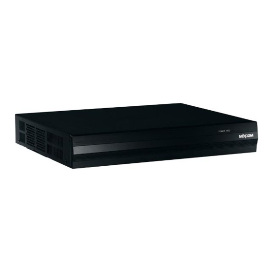
Physical Features Front Panel Rear Panel Antenna Antenna RS232 Line-in Antenna Power LED HDD LED Power Reset HDMI1 ~ HDMI3 USB2.0 USB3.0 SPDIF Line-out Switch DC-in Copyright © 2013 NEXCOM International Co., Ltd. All Rights Reserved. NDiS 165 User Manual... -
Page 16: Hardware Specifications
▪ 3x antenna hole for Wi-Fi and TV tuner ▪ Windows 7 / WES7 / Windows 8 / Linux ▪ 1x Power switch with LED ▪ 1x Reset switch Copyright © 2013 NEXCOM International Co., Ltd. All Rights Reserved. NDiS 165 User Manual... -
Page 17: Mechanical Dimensions
Chapter 1: Product Introduction Mechanical Dimensions Copyright © 2013 NEXCOM International Co., Ltd. All Rights Reserved. NDiS 165 User Manual... -
Page 18: Chapter 2: Jumpers And Connectors
Static electricity can damage many of the electronic ▪ Use correct screws and do not over tighten screws. components. Humid environments tend to have less static electricity than Copyright © 2013 NEXCOM International Co., Ltd. All Rights Reserved. NDiS 165 User Manual... -
Page 19: Locations Of The Jumpers And Connectors
Chapter 2: Jumpers and Connectors Locations of the Jumpers and Connectors The figure below is the main board used in the NDiS 165. It shows the locations of the jumpers and connectors. CON1 LAN1 CON3 CON2 CN12 CN13 CN14 J8 CN15... -
Page 20: Jumper Settings
(on) and open (off). Two-Pin Jumpers: Open (Left) and Short (Right) Three-Pin Jumpers: Pins 1 and 2 are Short Copyright © 2013 NEXCOM International Co., Ltd. All Rights Reserved. NDiS 165 User Manual... -
Page 21: Jumpers
RTC Control Connector Connector type: 1x3 3-pin header, 2.54mm pitch Connector location: JP10 Settings 1-2 On Normal mode 2-3 On Clear CMOS Settings VRTC_3V VCC_RTC RTC_SHD Copyright © 2013 NEXCOM International Co., Ltd. All Rights Reserved. NDiS 165 User Manual... -
Page 22: Connector Pin Definitions
Connector location: CN1 Definition Definition Definition +12V TMDS DATA2+ +12V TMDS DATA2- TMDS DATA1+ TMDS DATA1- TMDS DATA0+ EGND TMDS DATA0- TMDS CLOCK+ TMDS CLOCK- HOT PLUG DETECT Copyright © 2013 NEXCOM International Co., Ltd. All Rights Reserved. NDiS 165 User Manual... -
Page 23: Lan And Dual Usb2.0 Ports
Connector location: CON2 LINK Definition Definition Definition Definition TD1+ +5V_1 D-_1 TD1- TD2+ D+_1 TD2- TD3+ +5V_2 D-_2 TD3- TD4+ D+_2 TD4- TCTG LVCC SPDLED ACTLED LILED Copyright © 2013 NEXCOM International Co., Ltd. All Rights Reserved. NDiS 165 User Manual... -
Page 24: Lan And Dual Usb3.0 Ports
Connector location: CON3 LINK Definition Definition Definition Definition MDX1+ VBUS1 MDX1- MDX2+ MDX2- MDX3+ STDA_SSRX1- STDA_SSRX1+ MDX3- MDX4+ STDA_SST1- MDX4- STDA_SST1+ VBUS2 STDA_SSRX2- STDA_SSRX2+ STDA_SSTX2- STDA_SSTX2+ Copyright © 2013 NEXCOM International Co., Ltd. All Rights Reserved. NDiS 165 User Manual... -
Page 25: Dual Rs232 Connector
S/PDIF Connector Connector type: RJ45 Connector type: S/PDIF Connector Connector location: LAN1A and LAN1B Connector location: CN2 LAN1A Definition Definition Definition SPDIF_OUT SPD_3V3 LAN1B Definition Definition Copyright © 2013 NEXCOM International Co., Ltd. All Rights Reserved. NDiS 165 User Manual... -
Page 26: Dual Rs232 Connector
Connector location: CN3 Line-in Line-out LAN1A Definition Definition LINE IN L LINE OUT L LINE IN JD LINE OUT JD LINE IN R LINE OUT R Copyright © 2013 NEXCOM International Co., Ltd. All Rights Reserved. NDiS 165 User Manual... -
Page 27: Internal Connectors
Connector location: J7 & J8 Connector location: CN12 & CN13 (Data), CN15 & CN16 (Power) CN12 & CN13 Definition Definition SATA_TXP SATA_TXN SATA_RXP SATA_RXN CN15 & CN16 Definition +12V Copyright © 2013 NEXCOM International Co., Ltd. All Rights Reserved. NDiS 165 User Manual... -
Page 28: Rs232 Connectors
Connector type: 2x5 10-pin header, 2.0mm pitch Connector type: 1x5 5-pin header, 2.54mm pitch Connector location: CN18 & CN19 Connector location: JP6, JP8 & JP9 Definition Definition Definition +V3.3ALW MRST C2CK Copyright © 2013 NEXCOM International Co., Ltd. All Rights Reserved. NDiS 165 User Manual... -
Page 29: Rtc Battery Connector
Power-in Connector Connector type: 1x2 2-pin header JST, 1.25mm pitch Connector type: 2x2 4-pin header AUX Connector location: J3 Connector location: CON1 Definition Definition VBAT1 +12V +12V Copyright © 2013 NEXCOM International Co., Ltd. All Rights Reserved. NDiS 165 User Manual... -
Page 30: Mcu Debug Port
Connector type: 1x3 3-pin header, 2.54mm pitch Connector type: 1x3 3-pin header Wafer, 1.0mm pitch Connector location: JP7, JP5, JP2 & JP3 Connector location: J6 Definition Definition SMB_SDA SMB_SCL Copyright © 2013 NEXCOM International Co., Ltd. All Rights Reserved. NDiS 165 User Manual... -
Page 31: Port 80 Connector
Connector location: J2 Connector location: JP11 Definition Definition Definition Definition VCC3_S VCC3_S GP_IN0 GP_OUT0 LPC_AD0 LPC_AD1 GP_IN1 GP_OUT1 LPC_AD2 LPC_AD3 GP_IN2 GP_OUT2 LPC_FRAME# LPC_CLK0 GP_IN3 GP_OUT3 SIO_RST# Copyright © 2013 NEXCOM International Co., Ltd. All Rights Reserved. NDiS 165 User Manual... -
Page 32: Mini-Pcie Connector
D15VS +3.3B_MINI UIM_VPP SMB_CLK mPCIE_TX_N LED_WLAN# D15VS SMB_DATA CLKREQ# mPCIE_TX_P MINICARD1_DIS# UIM_PWR WLAN_RESET# D15VS UIM_DATA USB_IN mPCIE_RX_N MC_PCIE_CLK_N +3.3B_MINI UIM_CLK USB_IP mPCIE_RX_P PRE-DEC MC_PCIE_CLK_P +3.3B_MINI +3.3B_MINI Copyright © 2013 NEXCOM International Co., Ltd. All Rights Reserved. NDiS 165 User Manual... -
Page 33: Mini-Pcie Connector
Definition Definition PCIE_WAKE# +3.3B_MINI D15VS +3.3B_MINI SMB_CLK mPCIE_TX_N LED_WLAN# D15VS SMB_DATA CLKREQ# mPCIE_TX_P MINICARD1_DIS# WLAN_RESET# D15VS USB_IN mPCIE_RX_N MC_PCIE_CLK_N +3.3B_MINI USB_IP mPCIE_RX_P PRE-DEC MC_PCIE_CLK_P +3.3B_MINI +3.3B_MINI Copyright © 2013 NEXCOM International Co., Ltd. All Rights Reserved. NDiS 165 User Manual... -
Page 34: Sim Card Slot
Chapter 2: Jumpers and Connectors SIM Card Slot Connector location: CN14 Definition Definition UIM_PWR2 UIM_RST2 UIM_CLK2 UIM_DAT2 Copyright © 2013 NEXCOM International Co., Ltd. All Rights Reserved. NDiS 165 User Manual... -
Page 35: Chapter 3: System Setup
Remove these screws and put them in a safe place for later use. Rear 2. Once all the screws are removed, from the front, push the cover forward to remove it. Right side Copyright © 2013 NEXCOM International Co., Ltd. All Rights Reserved. NDiS 165 User Manual... -
Page 36: Installing A So-Dimm
SO-DIMM slots 4. While pushing the SO-DIMM into the position, the lock will close automatically. 2. Release the lock on the SO-DIMM slots. Lock Copyright © 2013 NEXCOM International Co., Ltd. All Rights Reserved. NDiS 165 User Manual... -
Page 37: Installing The Cpu
1. With the top cover removed, loosen the mounting screws that secure 2. Now remove the heat sink to access the CPU socket. the heat sink to the chassis. CPU socket Copyright © 2013 NEXCOM International Co., Ltd. All Rights Reserved. NDiS 165 User Manual... - Page 38 CPU must align with the white triangular mark on the mainboard. White triangular Gold triangular Handle the CPU by its edges and avoid touching the pins. Locked Unlocked Copyright © 2013 NEXCOM International Co., Ltd. All Rights Reserved. NDiS 165 User Manual...
- Page 39 Use a screwdriver to turn the screw to its locked position. Do not force the CPU into the socket. Forcing the CPU into the CAUTION! CAUTION! CAUTION! socket may bend the pins and damage the CPU. Copyright © 2013 NEXCOM International Co., Ltd. All Rights Reserved. NDiS 165 User Manual...
- Page 40 7. Align the mounting screws on the heat sink with the mounting holes on the board then tighten the screws to secure the heat sink in place. Mounting Mounting hole screw Copyright © 2013 NEXCOM International Co., Ltd. All Rights Reserved. NDiS 165 User Manual...
-
Page 41: Installing A 2.5" Hdd Storage
2. Place the HDD bracket on a firm surface, then put the HDD onto the bracket. Make sure the connector side of the HDD is facing the direction circled in the diagram below. Connector side Copyright © 2013 NEXCOM International Co., Ltd. All Rights Reserved. NDiS 165 User Manual... - Page 42 4. Once secured, slide the provided dampers into the damper opening on the mounting holes on the HDD, then tighten 4 screws into the holes. the mounting bracket as depicted in the diagram below. Damper Copyright © 2013 NEXCOM International Co., Ltd. All Rights Reserved. NDiS 165 User Manual...
- Page 43 6. Place the HDD bracket’s base on top of the copper standoffs with the 8. Fasten screws into the holes to secure it. mounting holes aligned. Copper standoff Screw Copyright © 2013 NEXCOM International Co., Ltd. All Rights Reserved. NDiS 165 User Manual...
- Page 44 9. Connect the SATA data and power cables to the connector on the HDD. 10. Connect the SATA data and power cables to the connectors CN12 and CN15 respectively. SATA power SATA data/power cable SATA data Copyright © 2013 NEXCOM International Co., Ltd. All Rights Reserved. NDiS 165 User Manual...
-
Page 45: Installing A Wireless Lan Module
2. Locate the mini-PCIe connector (CN11) on the mainboard. If the HDD is installed, please remove it to locate the connector. Antenna hole covers Mini-PCIe connector (CN11) Copyright © 2013 NEXCOM International Co., Ltd. All Rights Reserved. NDiS 165 User Manual... - Page 46 4. Insert the 2 rings (ring 1 then ring 2) into the Wi-Fi antenna jacks. angle until the gold-plated connector on the edge of the module completely disappears inside the slot. Then secure it with screws. Screw Ring1 Ring2 Copyright © 2013 NEXCOM International Co., Ltd. All Rights Reserved. NDiS 165 User Manual...
- Page 47 6. Replace the heatsink and the top cover, then connect the external antenna jacks to the antenna holes then tighten the rings. antennas to the Wi-Fi antenna jacks. RF cable Antenna jack Antenna Copyright © 2013 NEXCOM International Co., Ltd. All Rights Reserved. NDiS 165 User Manual...
-
Page 48: Installing A Tv Tuner Module
2. Locate the mini-PCIe connector (CN11) on the mainboard. If the HDD is installed, please remove it to locate the connector. Antenna hole cover Mini-PCIe connector (CN11) Copyright © 2013 NEXCOM International Co., Ltd. All Rights Reserved. NDiS 165 User Manual... - Page 49 4. Insert the 2 rings (ring 1 then ring 2) into the antenna jack. until the gold-plated connector on the edge of the module completely disappears inside the slot. Then secure it with screws. Screw Copyright © 2013 NEXCOM International Co., Ltd. All Rights Reserved. NDiS 165 User Manual...
- Page 50 6. Wire the cable to the rear of the chassis and mount the antenna jack to the antenna hole then tighten the rings. RF cable Antenna jack Copyright © 2013 NEXCOM International Co., Ltd. All Rights Reserved. NDiS 165 User Manual...
- Page 51 Chapter 3: System Setup 7. Replace the top cover, then connect the external antenna to the antenna jack. Antenna Copyright © 2013 NEXCOM International Co., Ltd. All Rights Reserved. NDiS 165 User Manual...
-
Page 52: Installing A 3G Module
2. Locate the mini-PCIe connector (CN10) on the mainboard. If the HDD is installed, please remove it to locate the connector. Antenna hole cover Mini-PCIe connector (CN10) Copyright © 2013 NEXCOM International Co., Ltd. All Rights Reserved. NDiS 165 User Manual... - Page 53 4. Insert the 2 rings (ring 1 then ring 2) into the antenna jacks. until the gold-plated connector on the edge of the module completely disappears inside the slot. Then secure it with screws. Screw Ring1 Ring2 Copyright © 2013 NEXCOM International Co., Ltd. All Rights Reserved. NDiS 165 User Manual...
- Page 54 6. Wire the cable to the rear of the chassis and mount the antenna jack to the antenna hole then tighten the rings. RF cable Antenna jack Copyright © 2013 NEXCOM International Co., Ltd. All Rights Reserved. NDiS 165 User Manual...
- Page 55 Chapter 3: System Setup 7. Replace the top cover, then connect the external antennas to the Wi-Fi antenna jacks. Antenna Copyright © 2013 NEXCOM International Co., Ltd. All Rights Reserved. NDiS 165 User Manual...
-
Page 56: Removing The Fan Modules
2. Remove the wall mount brackets to locate the fan modules’ cover and loosen the screws on the cover. 1. Loosen the screws holding the wall mount bracket. Screw Screw 3. Remove the fan modules. Copyright © 2013 NEXCOM International Co., Ltd. All Rights Reserved. NDiS 165 User Manual... -
Page 57: Wall Mount Installation
Chapter 3: System Setup Wall Mount Installation VESA Mount Installation (Optional) Screw (#6-32) Screw (#6-32) Wall mount bracket VESA mount bracket (For System) VESA mount bracket (For VESA Arm) Copyright © 2013 NEXCOM International Co., Ltd. All Rights Reserved. NDiS 165 User Manual... -
Page 58: Chapter 4: Bios Setup
Chapter 4: BIOS Setup Chapter 4: BIOS Setup This chapter describes how to use the BIOS setup program for the NDiS 165. The settings made in the setup program affect how the computer performs. The BIOS screens provided in this chapter are for reference only and may It is important, therefore, first to try to understand all the setup options, and change if the BIOS is updated in the future. -
Page 59: Default Configuration
Powering on the computer and immediately pressing <Del> allows you to enter Setup. Load optimized default values. Press the key to enter Setup: Saves and exits the Setup program. Press <Enter> to enter the highlighted sub¬menu Copyright © 2013 NEXCOM International Co., Ltd. All Rights Reserved. NDiS 165 User Manual... - Page 60 When “” appears on the left of a particular field, it indicates that a submenu which contains additional options are available for that field. To display the submenu, move the highlight to that field and press Copyright © 2013 NEXCOM International Co., Ltd. All Rights Reserved. NDiS 165 User Manual...
-
Page 61: Bios Setup Utility
+/-: Change Opt. F1: General Help F2: Previous Values F3: Optimized Defaults F4: Save & Exit ESC: Exit Version 2.15.1226. Copyright (C) 2012 American Megatrends, Inc. Copyright © 2013 NEXCOM International Co., Ltd. All Rights Reserved. NDiS 165 User Manual... -
Page 62: Advanced
F1: General Help F2: Previous Values wake on the hr::min::sec specified. F3: Optimized Defaults F4: Save & Exit ESC: Exit Version 2.15.1226. Copyright (C) 2012 American Megatrends, Inc. Copyright © 2013 NEXCOM International Co., Ltd. All Rights Reserved. NDiS 165 User Manual... -
Page 63: Acpi Settings
Select the highest ACPI sleep state the system will enter when the suspend button is pressed. The options are Suspend Disabled and S3 (Suspend to RAM). Lock Legacy Resources Enables or disables lock of legacy resources. Copyright © 2013 NEXCOM International Co., Ltd. All Rights Reserved. NDiS 165 User Manual... - Page 64 F4: Save & Exit F4: Save & Exit ESC: Exit ESC: Exit Version 2.15.1226. Copyright (C) 2012 American Megatrends, Inc. Version 2.15.1226. Copyright (C) 2012 American Megatrends, Inc. Copyright © 2013 NEXCOM International Co., Ltd. All Rights Reserved. NDiS 165 User Manual...
- Page 65 When power returns after an AC power failure, the system OnChip IDE Mode will automatically power-on. Configures the IDE mode as Legacy or Native. SATA IDE Combined Mode Enables or disables SATA IDE combined mode. Copyright © 2013 NEXCOM International Co., Ltd. All Rights Reserved. NDiS 165 User Manual...
-
Page 66: Ide Configuration
Legacy USB Support Enabled Enables Legacy USB. Disabled Keeps USB devices available only for EFI applications. USB 3.0 Support Enables or disables the USB 3.0 controller. Copyright © 2013 NEXCOM International Co., Ltd. All Rights Reserved. NDiS 165 User Manual... -
Page 67: Super Io Configuration
Displays the Super I/O chip used on the board. Enables or disables the serial port. Change Settings Selects an optimal setting for the Super IO device. Copyright © 2013 NEXCOM International Co., Ltd. All Rights Reserved. NDiS 165 User Manual... - Page 68 Detects and displays the current system temperature. CPU Core Temperature Detects and displays the current CPU core temperature. SysFan Speed Detects and displays the current SysFan speed. Copyright © 2013 NEXCOM International Co., Ltd. All Rights Reserved. NDiS 165 User Manual...
-
Page 69: Boot
Launch PXE OpROM Policy Controls the execution of UEFI and legacy PXE OpROM. The options are Do not launch and Legacy only. Copyright © 2013 NEXCOM International Co., Ltd. All Rights Reserved. NDiS 165 User Manual... -
Page 70: Security
Select this to configure the HDD security password. Restore Defaults To restore the BIOS to default settings, select this field then press <Enter>. A dialog box will appear. Confirm by selecting Yes. Copyright © 2013 NEXCOM International Co., Ltd. All Rights Reserved. NDiS 165 User Manual... -
Page 71: Appendix A: Watchdog Timer
(1/48MHz) = 1.046s) 1: Enable. Disable / Enable the Watchdog Timer I output low pulse to the KBRST# pin (PIN59) R / W 0: Disable. 1: Enable. Reversed Copyright © 2013 NEXCOM International Co., Ltd. All Rights Reserved. NDiS 165 User Manual... - Page 72 0: Watchdog Timer I is running. Write “0” Clear 1: Watchdog Timer I issues time-out event. R / W These bits select the IRQ resource for the Watchdog Timer I Copyright © 2013 NEXCOM International Co., Ltd. All Rights Reserved. NDiS 165 User Manual...
-
Page 73: Appendix B: Supported Eyefinity Modes
3 x 1 Portrait 1 x 3 Landscape 1 x 3 Portrait 2 x 1 Landscape 2 x 1 Portrait 1 x 2 Landscape 1 x 2 Portrait Copyright © 2013 NEXCOM International Co., Ltd. All Rights Reserved. NDiS 165 User Manual... - Page 74 Appendix B: Supported Eyefinity Modes Number Configuration Diagram Other Display Setting Display 3x1 Landscape Extended or Disable 3x1 Portrait Extended or Disable 1x3 Landscape Extended or Disable Copyright © 2013 NEXCOM International Co., Ltd. All Rights Reserved. NDiS 165 User Manual...
- Page 75 Configuration Diagram Other Display Setting Display 1x3 Portrait Extended or Disable 2x1 Landscape Extended or Disable 2x1 Portrait Extended or Disable 1x2 Landscape Extended or Disable Copyright © 2013 NEXCOM International Co., Ltd. All Rights Reserved. NDiS 165 User Manual...
- Page 76 Appendix B: Supported Eyefinity Modes Number Configuration Diagram Other Display Setting Display 1x2 Portrait Extended or Disable Copyright © 2013 NEXCOM International Co., Ltd. All Rights Reserved. NDiS 165 User Manual...
Need help?
Do you have a question about the NDiS 165 and is the answer not in the manual?
Questions and answers