
Related Manuals for Nexcom NDiS B561


Summary of Contents for Nexcom NDiS B561
- Page 1 NEXCOM International Co., Ltd. Intelligent Platform & Services Business Unit Digital Signage Platform NDiS B561 User Manual NEXCOM International Co., Ltd. www.nexcom.com Published August 2023...
-
Page 2: Table Of Contents
ATX +12V Power Connector ............17 Front Panel ..................2 Battery Connector ................17 Rear Panel ...................2 Fan Connectors ................18 Hardware Specifications ................3 GPIO Connector ................18 Mechanical Dimensions ................5 Copyright © 2023 NEXCOM International Co., Ltd. All Rights Reserved. NDiS B561 User Manual... - Page 3 Installing a M.2 Storage Module (M2M2) ..........36 Installing a M.2 WiFi Module ...............37 (Key E 2230) ..................37 Installing a M.2 Mobile Network Module ..........39 (Key B 3042/3052) ................39 Copyright © 2023 NEXCOM International Co., Ltd. All Rights Reserved. NDiS B561 User Manual...
-
Page 4: Preface
No describes how to keep the system CE compliant. part of this manual may be reproduced, copied, translated or transmitted in any form or by any means without the prior written consent from NEXCOM Declaration of Conformity International Co., Ltd. -
Page 5: Rohs Compliance
(Cr6+) < 0.1% or 1,000ppm, Polybrominated biphenyls (PBB) < 0.1% or 1,000ppm, and Polybrominated diphenyl Ethers (PBDE) < 0.1% or 1,000ppm. In order to meet the RoHS compliant directives, NEXCOM has established an engineering and manufacturing task force to implement the introduction of green products. -
Page 6: Warranty And Rma
“NEXCOM RMA Service Form” for the RMA number apply process. ▪ If RMA goods can not be repaired, NEXCOM will return it to the customer without any charge. ▪ Customers can send back the faulty products with or without accessories (manuals, cable, etc.) and any components from the card, such as CPU... - Page 7 ESD workstation. If no such station is available, you can provide some ESD protection by wearing an antistatic wrist strap and attaching it to a metal part of the computer chassis. Copyright © 2023 NEXCOM International Co., Ltd. All Rights Reserved. NDiS B561 User Manual...
-
Page 8: Safety Information
▪ The instructions shall require connection of the equipment protective earthing conductor to the installation protective earthing conductor (for example, by means of a power cord connected to a socket-outlet with earthing connection). viii Copyright © 2023 NEXCOM International Co., Ltd. All Rights Reserved. NDiS B561 User Manual... -
Page 9: Safety Precautions
12Vdc, 8A or 8.33A minimum, Tma 40 degree power source to avoid damage by transient overvoltage. C minimum and altitude 2000m. If further assistance is needed, please contact NEXCOM for further information. Copyright © 2023 NEXCOM International Co., Ltd. All Rights Reserved. NDiS B561 User Manual... -
Page 10: Technical Support And Assistance
Preface Technical Support and Assistance Conventions Used in this Manual 1. For the most updated information of NEXCOM products, visit NEXCOM’s Warning: website at www.nexcom.com. Information about certain situations, which if not observed, can cause personal injury. This will prevent injury to yourself 2. -
Page 11: Global Service Contact Information
Tel: +886-2-8226-7786 Tel: +886-2-8976-3077 Beitun District, Fax: +886-2-8226-7782 Email: sales@diviotec.com Taichung City, 406, Taiwan, R.O.C. Email: services@tmrtek.com www.diviotec.com Tel: +886-4-2249-1179 www.tmrtek.com Fax: +886-4-2249-1172 Email: jacobhuang@nexaiot.com www.nexaiot.com Copyright © 2023 NEXCOM International Co., Ltd. All Rights Reserved. NDiS B561 User Manual... - Page 12 9F, Tamachi Hara Bldg., LongGang District, 4-11-5, Shiba Minato-ku, ShenZhen, 518112, China Tokyo, 108-0014, Japan Tel: +86-755-8364-7768 Tel: +81-3-5419-7830 Fax: +86-755-8364-7738 Fax: +81-3-5419-7832 Email: steveyang@nexcom.com.tw Email: sales@nexcom-jp.com www.nexcom.cn www.nexcom-jp.com Copyright © 2023 NEXCOM International Co., Ltd. All Rights Reserved. NDiS B561 User Manual...
-
Page 13: Package Contents
Preface Package Contents Before continuing, verify that the NDiS B561 package that you received is complete. Your package should have all the items listed in the following table. Item Part Number Name 19W00B56101X0 NDiS B561 System 7400120025X00 POWER ADAPTER FSP:FSP120-AHAN3 5060200706X00 60x20x2mm Thermal Pad apply to top side M.2 SSD... -
Page 14: Ordering Information
The following information below provides ordering information for NDiS B561. NDiS B561 (P/N: 10W00B56101X0) 12th Gen Intel ® Core™ processor (up to 35W) fanless system, Intel ® Q670E chipset. Copyright © 2023 NEXCOM International Co., Ltd. All Rights Reserved. NDiS B561 User Manual... -
Page 15: Chapter 1: Product Introduction
8 x USB 3.2, 3 x LAN ports (including 2 x PoE ports), Wi-Fi 6E and 4G, 5G support. The NDiS B561 can be used for both indoor and out-door applications such as visual edge computing, AI recognization, public transportation, outdoor bus station, and even smart stadium. -
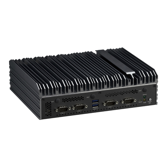
Page 16: Physical Features
Chapter 1: Product Introduction Physical Features Front Panel Rear Panel Power Power Mic-In Line-Out Button COM4 COM3 COM2 COM1 USB 3.2 HDMI DC in Reset USB 3.2 Copyright © 2023 NEXCOM International Co., Ltd. All Rights Reserved. NDiS B561 User Manual... -
Page 17: Hardware Specifications
– COM1: RS232/422/485 ▪ 1 x SIM slot – COM2~4: RS232 ▪ 3 x Antenna hole Power Supply ▪ 1 x External AC/DC 12V/120W power adapter Copyright © 2023 NEXCOM International Co., Ltd. All Rights Reserved. NDiS B561 User Manual... - Page 18 ▪ Humidity: 10 to 95% (non-condensing) Certification ▪ CE approval ▪ FCC Class A Dimensions ▪ 238mm (W) x 192mm (D) x 67.29mm (H) Operating System ▪ Win11/Win10/Linux Kernel Copyright © 2023 NEXCOM International Co., Ltd. All Rights Reserved. NDiS B561 User Manual...
-
Page 19: Mechanical Dimensions
Chapter 1: Product Introduction Mechanical Dimensions 268.0 253.6 73.7 238.0 Copyright © 2023 NEXCOM International Co., Ltd. All Rights Reserved. NDiS B561 User Manual... -
Page 20: Chapter 2: Jumpers And Connectors
Static electricity can damage many of the electronic ▪ Use correct screws and do not over tighten screws. components. Humid environments tend to have less static electricity than Copyright © 2023 NEXCOM International Co., Ltd. All Rights Reserved. NDiS B561 User Manual... -
Page 21: Locations Of The Jumpers And Connectors For Ndib B561
Locations of the Jumpers and Connectors for NDiB B561 The following figures show the top and bottom views of the NDiS B561, which is the main board used in the NDiS B561. They illustrate the locations of the jumpers and connectors. For more detailed information on pin settings and definitions marked in pink on this figure, please refer to this chapter. -
Page 22: Bottom View
Chapter 2: Jumpers and Connectors Bottom View M2M2 DIMM2 Copyright © 2023 NEXCOM International Co., Ltd. All Rights Reserved. NDiS B561 User Manual... -
Page 23: Jumper Settings
(on) and open (off). Two-Pin Jumpers: Open (Left) and Short (Right) Three-Pin Jumpers: Pins 1 and 2 are Short Copyright © 2023 NEXCOM International Co., Ltd. All Rights Reserved. NDiS B561 User Manual... -
Page 24: Jumper Settings
AT Mode 1-2 On COM2 RI = Ring (Default) 2-3 On ATX Mode (Default) 2-3 On COM2 RI = +5V 4-5 On COM2 RI = +12V Copyright © 2023 NEXCOM International Co., Ltd. All Rights Reserved. NDiS B561 User Manual... -
Page 25: Connector Pin Definitions
Connector type: D-Sub CON 9P 90D Male Connector location: DCIN Connector location: COM1 ~ COM4 Definition Definition Definition DCD# +12VSUS DTR# +12VSUS DSR# RTS# CTS# CGND CGND CGND Copyright © 2023 NEXCOM International Co., Ltd. All Rights Reserved. NDiS B561 User Manual... -
Page 26: Hdmi Connector
Connector type: HDMI CON 19P G/F R/A SMT Connector location: HDMI Definition Definition HDMI1_TX2P HDMI1_TX2N HDMI1_TX1P HDMI1_TX1N HDMI1_TX0P HDMI1_TX0N HDMI1_CLK_P HDMI1_CLK_N HDMI1_SCL HDMI1_SDA HDMI1_P5V HDMI1_HPD CGND CGND CGND CGND Copyright © 2023 NEXCOM International Co., Ltd. All Rights Reserved. NDiS B561 User Manual... -
Page 27: Hdmi Connectors
HDMI1_TX0N HDMI1_CLK_P HDMI1_CLK_N HDMI2_SCL HDMI2_SDA HDMI2_P5V HDMI1_SCL HDMI1_SDA HDMI2_HPD HDMI1_P5V GND1 CGND GND2 CGND HDMI1_HPD GND3 CGND GND4 CGND HDMI2_TX2P GND5 CGND GND6 CGND HDMI2_TX2N HDMI2_TX1P Copyright © 2023 NEXCOM International Co., Ltd. All Rights Reserved. NDiS B561 User Manual... -
Page 28: Lan Ports
LAN1_MDI0N LAN1_MDI1P LAN1_MDI1N LAN1_MDI1P LAN1_MDI2P TCTG LAN1_MDI2N LAN1_MDI1N LAN1_MDI2P LAN1_MDI2N LAN1_MDI3P LAN1_MDI3N LAN1_MDI3P LAN1_MDI3N LAN1_LED_LINK100# LAN1_LED_LINK2500# LAN1LED1G# LAN1LED100# LAN1_LED_ACT# LAN1_LED_ACT_POWER LAN1LEDACTN LAN1ACTPW CGND CGND CGND CGND Copyright © 2023 NEXCOM International Co., Ltd. All Rights Reserved. NDiS B561 User Manual... -
Page 29: Power Button
Reset Button Connector type: WtoB CON 2P, 1.0mm, S/T Connector type: Header 1X2P, 2.0mm, S/T Connector location: Power Button Connector location: Reset Button Definition Definition PWRBTN# RESET# Copyright © 2023 NEXCOM International Co., Ltd. All Rights Reserved. NDiS B561 User Manual... -
Page 30: Usb Ports
Chapter 2: Jumpers and Connectors USB Ports Connector type: USB 3.2 Definition Definition USB2_3N USB2_3P USB3_RX3N USB3_RX3P USB3_TX3N USB3_TX3P USB2_4N USB2_4P USB3_RX4N USB3_RX4P USB3_TX4N USB3_TX4P CGND CGND CGND CGND Copyright © 2023 NEXCOM International Co., Ltd. All Rights Reserved. NDiS B561 User Manual... -
Page 31: Internal Connectors
Connector type: ATX Power CON 2x4 Male 180D Connector type: WtoB CON 2P, 1.25mm, R/A Connector location: ATX8P Connector location: BAT1 Definition Definition Definition +12V +12V +12V +12V Copyright © 2023 NEXCOM International Co., Ltd. All Rights Reserved. NDiS B561 User Manual... -
Page 32: Fan Connectors
Connector type: WtoB CON 10P, 1.0mm, S/T Connector location: CPU_Fan, Sys_Fan Connector location: GPIO Definition Definition Definition +12V GPO0 GPO1 FAN SPEED DETECT GPO2 GPO3 FAN SPEED CONTROL GPI0 GPI1 GPI2 GPI3 Copyright © 2023 NEXCOM International Co., Ltd. All Rights Reserved. NDiS B561 User Manual... -
Page 33: Mic-In Line-Out Connector
Chapter 2: Jumpers and Connectors MIC-In LINE-Out Connector Connector type: WtoB CON 9P, 1.0mm, S/T Connector location: MIC_LOUT Definition Definition LINE_OUT-R LINE_JD AUDGND LINE_OUT-L AUDGND MIC_OUT-R MIC_JD MIC_OUT-L AUDGND Copyright © 2023 NEXCOM International Co., Ltd. All Rights Reserved. NDiS B561 User Manual... -
Page 34: M.2 Key B 3042/3052 Slot
CLKREQ# CLK_DN WAKE# CLK_DP Telit FN980 PCIe/USB Select Pin CONFIG0 WWAN_GPS_ON USB3_RXN UIM_RESET RESET(1.8V) SUS_CLK USB3_RXP UIM_CLK CONFIG1 3.3V UIM_DATA 3.3V USB3_TXN UIM_PWR 3.3V USB3_TXP CONFIG2 Copyright © 2023 NEXCOM International Co., Ltd. All Rights Reserved. NDiS B561 User Manual... -
Page 35: M.2 Key E 2230 Slot
GND9 RESERVED SDIO_WAKE# UART_RXD PERP1 UIM_SWP SDIO_RESET# PERN1 UIM_POWER_SNK GND10 UIM_POWER_SRC GND4 UART_CTS PEFCLKP1 3.3V_3 PETP0 UART_RTS PEFCLKN1 3.3V_4 PETN0 RESERVED_1 GND11 GND5 RESERVED_2 PERP0 RESERVED_3 Copyright © 2023 NEXCOM International Co., Ltd. All Rights Reserved. NDiS B561 User Manual... -
Page 36: M.2 Key M 2280 Slot
SATA_TXN(PCIE0_TXN) PCIE3_TXN VCC3 SATA_TXP(PCIE0_TXP) RESET# PCIE3_TXP VCC3 CLKREQ# VCC3 CLK_PCIEN WAKE# PCIE2_RXN VCC3 CLK_PCIEP PCIE2_RXP M2M_PEDET VCC3 PCIE2_TXN PCIE2_TXP M2M_PEDET VCC3 VCC3 PCIE1_RXN VCC3 PCIE1_RXP PCIE1_TXN Copyright © 2023 NEXCOM International Co., Ltd. All Rights Reserved. NDiS B561 User Manual... -
Page 37: Sata Connectors
Connector type: SATA CON 7P, 1.27mm, S/T Connector type: WtoB CON 2P, 2.5mm, S/T Connector location: SATA1, SATA2 Connector location: SATA_PWR1, SATA_PWR2 Definition Definition SATA_TXP SATA_TXN SATA_RXN SATA_RXP Copyright © 2023 NEXCOM International Co., Ltd. All Rights Reserved. NDiS B561 User Manual... -
Page 38: Smbus/I2C Connector
Connector type: WtoB CON 4P, 2.0mm, S/T Connector type: WtoB CON 4P, 1.25mm, S/T Connector location: SMBUS Connector location: SPK Definition Definition VCC3 R_OUT- SMBCLK R_OUT+ SMBDAT L_OUT- L_OUT+ Copyright © 2023 NEXCOM International Co., Ltd. All Rights Reserved. NDiS B561 User Manual... -
Page 39: Usb 2.0 Connectors
Chapter 2: Jumpers and Connectors USB 2.0 Connectors Connector location: USB2_1112P, USB2_1314P Definition USB2N USB2P USB1N USB1P Copyright © 2023 NEXCOM International Co., Ltd. All Rights Reserved. NDiS B561 User Manual... -
Page 40: Led Indicators
Blinking Yellow Steady Yellow Power off No light No Active Connected Steady Yellow Disconnected / No light Read / Write non-working Read / Write working Blinking Yellow Copyright © 2023 NEXCOM International Co., Ltd. All Rights Reserved. NDiS B561 User Manual... -
Page 41: Block Diagram
Chapter 2: Jumpers and Connectors Block Diagram Copyright © 2023 NEXCOM International Co., Ltd. All Rights Reserved. NDiS B561 User Manual... -
Page 42: Chapter 3: System Setup
The screws on the front, rear, and bottom are used to secure the cover to the chassis. Remove the screws and put them in a safe place for later use. Copyright © 2023 NEXCOM International Co., Ltd. All Rights Reserved. NDiS B561 User Manual... - Page 43 Chapter 3: System Setup 2. Remove the top cover. Copyright © 2023 NEXCOM International Co., Ltd. All Rights Reserved. NDiS B561 User Manual...
-
Page 44: Installing A Cpu
2. Locate the CPU socket on the board. Unlock the socket by pushing the load lever down, moving it sideways until it is released from the retention tab. CPU Socket Load Lever Retention Tab Copyright © 2023 NEXCOM International Co., Ltd. All Rights Reserved. NDiS B561 User Manual... - Page 45 1. Handle the CPU by its edges and avoid touching the pins. CAUTION! CAUTION! 2. The CPU will fit only in one orientation and can easily be CAUTION! inserted without exerting any force. Copyright © 2023 NEXCOM International Co., Ltd. All Rights Reserved. NDiS B561 User Manual...
- Page 46 CPU. 6. Applying thermal paste before assembling the heatsink to ensure proper heat transfer between the CPU and the heatsink. Copyright © 2023 NEXCOM International Co., Ltd. All Rights Reserved. NDiS B561 User Manual...
-
Page 47: Installing A So-Dimm (Dimm1)
The ejector tabs at the ends of the socket will automatically snap into the locked position to hold the module in place. SO-DIMM 1 socket Copyright © 2023 NEXCOM International Co., Ltd. All Rights Reserved. NDiS B561 User Manual... -
Page 48: Installing A So-Dimm (Dimm2)
Remove the screw from the SO-DIMM cover at the bottom side. Refer to step 1 to secure the SO-DIMM cover back in place using the screw. Copyright © 2023 NEXCOM International Co., Ltd. All Rights Reserved. NDiS B561 User Manual... -
Page 49: Installing A M.2 Storage Module (M2M1)
Stick it to the original uses a plastic standoff but may be replaced with a screw. set of M.2 module for a better heat dissipation. Copyright © 2023 NEXCOM International Co., Ltd. All Rights Reserved. NDiS B561 User Manual... -
Page 50: Installing A M.2 Storage Module (M2M2)
M.2 slot at a 45-degree angle until the gold-plated connector on the edge of the module completely disappears into the slot. Refer to step 1 to secure the M.2 cover back in place using the screw. Copyright © 2023 NEXCOM International Co., Ltd. All Rights Reserved. NDiS B561 User Manual... -
Page 51: Installing A M.2 Wifi Module
M.2 Key E slot down on the M.2 module and insert the notch of the module into the corresponding notch in the middle of the plastic standoff. Plastic Standoff Copyright © 2023 NEXCOM International Co., Ltd. All Rights Reserved. NDiS B561 User Manual... - Page 52 The plastic standoff is subject to change depending on the packaging requirements. The installation process shown in this section uses a plastic standoff but may be replaced with a screw. Copyright © 2023 NEXCOM International Co., Ltd. All Rights Reserved. NDiS B561 User Manual...
-
Page 53: Installing A M.2 Mobile Network Module
M.2 Key E slot at a 45-degree angle until the gold-plated connector on the edge of the module completely disappears into the slot. M.2 Key B slot Mobile Network Module Copyright © 2023 NEXCOM International Co., Ltd. All Rights Reserved. NDiS B561 User Manual... -
Page 54: Chapter 4: Bios Setup
This chapter describes how to use the BIOS setup program for the NDiS B561. The settings made in the setup program affect how the computer performs. The BIOS screens provided in this chapter are for reference only and may It is important, therefore, first to try to understand all the setup options, and change if the BIOS is updated in the future. -
Page 55: Default Configuration
Powering on the computer and immediately pressing <Del> allows you to enter Setup. Load optimized default values. Press the key to enter Setup: Saves and exits the Setup program. Press <Enter> to enter the highlighted sub¬menu Copyright © 2023 NEXCOM International Co., Ltd. All Rights Reserved. NDiS B561 User Manual... - Page 56 When “” appears on the left of a particular field, it indicates that a submenu which contains additional options are available for that field. To display the submenu, move the highlight to that field and press Copyright © 2023 NEXCOM International Co., Ltd. All Rights Reserved. NDiS B561 User Manual...
-
Page 57: Main
The Main menu is the first screen that you will see when you enter the BIOS hours from 00 to 23. Minute displays minutes from 00 to 59. Second displays Setup Utility. seconds from 00 to 59. Copyright © 2023 NEXCOM International Co., Ltd. All Rights Reserved. NDiS B561 User Manual... -
Page 58: Advanced
USB Power State in S5 Setting incorrect field values may cause the system to Configure the USB power state in S5. malfunction. Copyright © 2023 NEXCOM International Co., Ltd. All Rights Reserved. NDiS B561 User Manual... - Page 59 When this field is set to Enabled, the VMM can utilize the additional hardware capabilities provided by Vanderpool Technology. Intel SpeedStep(tm) ® Enable or disable Intel SpeedStep. Copyright © 2023 NEXCOM International Co., Ltd. All Rights Reserved. NDiS B561 User Manual...
- Page 60 Chapter 4: BIOS Setup Efficient-core Information Performance-core Information This section is used to display the CPU E-core information. This section is used to display the CPU P-core information. Copyright © 2023 NEXCOM International Co., Ltd. All Rights Reserved. NDiS B561 User Manual...
- Page 61 Enable or disable BIOS support for security device. O.S. will not show security device. TCG EFI protocol and INT1A interface will not be available. SHA256 PCR Bank Enable or disable SHA256 PCR Bank. Copyright © 2023 NEXCOM International Co., Ltd. All Rights Reserved. NDiS B561 User Manual...
- Page 62 Select the highest ACPI sleep state the system will enter when the suspend button is pressed. The options are Suspend Disabled and S3 (Suspend to RAM). Copyright © 2023 NEXCOM International Co., Ltd. All Rights Reserved. NDiS B561 User Manual...
- Page 63 Displays the Super I/O chip used on the board. Onboard Serial Port 1 Mode Select this to change the serial port mode to RS232, RS422 or RS485. Copyright © 2023 NEXCOM International Co., Ltd. All Rights Reserved. NDiS B561 User Manual...
-
Page 64: About Bios Setup
CPUFAN Setting > CPUFAN Mode Select fan control mode. CPUFAN Setting > Manual PWM Configure the fan speed manually when the fan mode is set to Manual mode. Copyright © 2023 NEXCOM International Co., Ltd. All Rights Reserved. NDiS B561 User Manual... - Page 65 Enable or disable system wake on alarm event. Select FixedTime, system will wake on the hr::min::sec specified. Select DynamicTime, System will wake on the current time + Increase minutes. Copyright © 2023 NEXCOM International Co., Ltd. All Rights Reserved. NDiS B561 User Manual...
- Page 66 Enable or disable IPv4 PXE support. If disabled, the IPv4 boot option will not be created. Ipv6 PXE Support Enable or disable IPv6 PXE support. If disabled, the IPv6 boot option will not be created. Copyright © 2023 NEXCOM International Co., Ltd. All Rights Reserved. NDiS B561 User Manual...
-
Page 67: Bios Setup Utility
Adjust the boot sequence of the system. Boot Option #1 is the first boot device that the system will boot from, next will be #2 and so forth. Copyright © 2023 NEXCOM International Co., Ltd. All Rights Reserved. NDiS B561 User Manual... -
Page 68: Save & Exit
To exit the Setup utility without saving the changes, select this field then press <Enter>. You may be prompted to confirm again before exiting. You can also press <ESC> to exit without saving the changes. Copyright © 2023 NEXCOM International Co., Ltd. All Rights Reserved. NDiS B561 User Manual... - Page 69 GPI/O (General Purpose Input/Output) pins are provided for custom system design. This appendix provides definitions and its default setting for the ten GPI/O pins in the NDiS B561. The pin definition is shown in the following table: Pin No.
-
Page 70: Gpio Programming Sample Code
#define GPO1_LO outportb(0xA02, 0x00) #define GPO2_HI outportb(0xA02, GPO2) #define GPO2_LO outportb(0xA02, 0x00) #define GPO3_HI outportb(0xA02, GPO3) #define GPO3_LO outportb(0xA02, 0x00) void main(void) GPO2X; GPO0_HI; GPO1_LO; GPO2_HI; GPO3_LO; Copyright © 2021 NEXCOM International Co., Ltd. All Rights Reserved. NISE 52 User Manual... -
Page 71: Appendix B: Nct6126D Watchdog Programming Guide
PPendIx atCh roGrammInG uIde NDiS B561 features a watchdog timer that resets the CPU or generates an interrupt if the processor stops operating for any reason. This feature ensures system reliability in industrial standalone or unmanned environments. #define SUPERIO_PORT 0x2E...
Need help?
Do you have a question about the NDiS B561 and is the answer not in the manual?
Questions and answers