
Related Manuals for Nexcom NDiS 542


Summary of Contents for Nexcom NDiS 542
- Page 1 NEXCOM International Co., Ltd. Multi-Media Solutions Digital Signage Platform NDiS 542 User Manual NEXCOM International Co., Ltd. www.nexcom.com Published September 2012...
-
Page 2: Table Of Contents
Precautions ....................9 Fan Connectors ..................20 Jumper Settings ..................9 Panel LED Connector ................20 Locations of the Jumpers and Connectors ..........11 IR Connector ..................20 Jumpers ....................12 Mini-PCIe Slots ..................21 Copyright © 2012 NEXCOM International Co., Ltd. All Rights Reserved. NDiS 542 User Manual... - Page 3 Landscape and Portrait Mode Coordinate System ........62 Portrait Coordinate System..............63 Appendix B: Audio Driver Installation and Settings Installing the Audio Driver ..............65 Appendix C: Watchdog Timer Appendix D: Power Consumption Copyright © 2012 NEXCOM International Co., Ltd. All Rights Reserved. NDiS 542 User Manual...
-
Page 4: Preface
Acknowledgements The product(s) described in this manual complies with all applicable Euro- NDiS 542 is a trademark of NEXCOM International Co., Ltd. All other prod- pean Union (CE) directives if it has a CE marking. For computer systems to uct names mentioned herein are registered trademarks of their respective remain CE compliant, only CE-compliant parts may be used. - Page 5 < 0.1% or 1,000ppm, and Polybrominated diphenyl Ethers (PBDE) < 0.1% or 1,000ppm. In order to meet the RoHS compliant directives, NEXCOM has established an engineering and manufacturing task force in to implement the intro- duction of green products. The task force will ensure that we follow the...
- Page 6 ? Replace with 3rd party products if needed. the RMA number apply process. ? If RMA goods can not be repaired, NEXCOM will return it to the cus- tomer without any charge. ? Customers can send back the faulty products with or without acces- sories (manuals, cable, etc.) and any components from the card, such as...
-
Page 7: Safety Information
There is a danger of explosion if battery is incorrectly replaced. Replace only with the same or equivalent type recommended by the manufactur- er. Discard used batteries according to the manufacturer’s instructions. Copyright © 2012 NEXCOM International Co., Ltd. All Rights Reserved. NDiS 542 User Manual... -
Page 8: Safety Precautions
11. All cautions and warnings on the equipment should be noted. 19. The computer is provided with CD drives that comply with the ap- propriate safety standards including IEC 60825. viii Copyright © 2012 NEXCOM International Co., Ltd. All Rights Reserved. NDiS 542 User Manual... - Page 9 Technical Support and Assistance Conventions Used in this Manual Warning: Information about certain situations, which if not 1. For the most updated information of NEXCOM products, visit NEX- observed, can cause personal injury. This will prevent injury to COM’s website at www.nexcom.com.
- Page 10 Milton Keynes, Buckinghamshire Tel: +33 (0)1 40 90 33 35 MK8 0AB, United Kingdom Fax: +33 (0)1 40 90 31 01 Tel: +44-1908-267121 http://www.nexcom.eu Fax: +44-1908-262042 http://www.nexcom.eu Copyright © 2012 NEXCOM International Co., Ltd. All Rights Reserved. NDiS 542 User Manual...
- Page 11 Hall C, Block 17, Tian Xing Cui Lang Building, TEL: +86-755-833 7203 No. 49 Yunnan North Rd., FAX: +86-755-833 7213 Nanjing, 210018, China http://www.nexcom.cn Tel: +86-25-8315-3486 Fax: +86-25-8315-3489 http://www.nexcom.cn Copyright © 2012 NEXCOM International Co., Ltd. All Rights Reserved. NDiS 542 User Manual...
- Page 12 Preface Japan NEXCOM Japan 9F, Tamachi Hara Bldg., 4-11-5, Shiba Minato-ku, Tokyo, 108-0014, Japan Tel: +81-3-5419-7830 Fax: +81-3-5419-7832 http://www.nexcom-jp.com Copyright © 2012 NEXCOM International Co., Ltd. All Rights Reserved. NDiS 542 User Manual...
-
Page 13: Package Contents
Preface Package Contents Before continuing, verify that the NDiS 542 package that you received is complete. Your package should have all the items listed in the following table. Item Name Specification 50311F0100X00 (H)ROUND HEAD SCREW W/SPRING+FLAT WASHER P3x6 iso/SW6x0.5 NI... -
Page 14: Ordering Information
The following provides ordering information for NDiS 542. • NDiS 542 (P/N: 10W00054200X0) ® - Intel Core™ 2 Quad Q9400 processor ® - Intel P45 + ICH10 / S3 4300E GPU Copyright © 2012 NEXCOM International Co., Ltd. All Rights Reserved. NDiS 542 User Manual... -
Page 15: Chapter 1: Product Introduction
• Intel® Core™ 2 Duo/Core™ 2 Quad Platform • Dual GbE LAN • S3 4300E GPU • 6 x Serial Ports • 4 x DVI/4 x Audio • TV Tuner/WLAN Support Copyright © 2012 NEXCOM International Co., Ltd. All Rights Reserved. NDiS 542 User Manual... -
Page 16: Hardware Specifications
• Two RJ45 with LED connecter located by the OS • Support PXE LAN boot ROM for Ethernet boot up. • Support Wake on LAN (By 5Vsb Provided) Copyright © 2012 NEXCOM International Co., Ltd. All Rights Reserved. NDiS 542 User Manual... - Page 17 Internal • RTC tolerance less than 2 sec (24 hours) under 25 C environment - Two USB 2x5 pin-header x1 for USB x2. Supports u-DOC x1 Copyright © 2012 NEXCOM International Co., Ltd. All Rights Reserved. NDiS 542 User Manual...
-
Page 18: Ndis 542 System
• Color - Black • Mounting - Wall mount bracket • Cooling system - Main chip’s heat sink and 2 high speed system fans (RPM: 9200). Copyright © 2012 NEXCOM International Co., Ltd. All Rights Reserved. NDiS 542 User Manual... - Page 19 - Test time: 1 hour per axis - Total test time: 3 hours Shock • 50g peak acceleration (16 msec. duration) - HDD Certificate • CE • FCC Class A Copyright © 2012 NEXCOM International Co., Ltd. All Rights Reserved. NDiS 542 User Manual...
-
Page 20: Getting To Know Ndis 542
Indicates the status of the hard drive. COM Terminal Port RJ45 LAN Supports 4x RS232 compatible serial devices. Used to connect the system to a local area network. Copyright © 2012 NEXCOM International Co., Ltd. All Rights Reserved. NDiS 542 User Manual... -
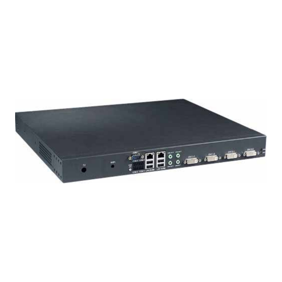
Page 21: Rear Panel
Rear Panel Power Supply RS232 On/Off switch Power Supply On/Off Switch Press to power-on or power-off the system. The COM port supports RS232 compatible serial devices. Copyright © 2012 NEXCOM International Co., Ltd. All Rights Reserved. NDiS 542 User Manual... -
Page 22: Mechanical Dimensions
Chapter 1: Product Introduction Mechanical Dimensions 426.20 max 7.5mm max 2.5mm max 2.5mm Copyright © 2012 NEXCOM International Co., Ltd. All Rights Reserved. NDiS 542 User Manual... -
Page 23: Chapter 2: Jumpers And Connectors
Chapter 2: Jumpers and Connectors This chapter describes how to set the jumpers on the motherboard. Note danger of static electricity exists. that the following procedures are generic for all NDiS 542. Precautions Before You Begin Computer components and electronic circuit boards can be damaged by ▪... - Page 24 (on) and open (off). Two-Pin Jumpers: Open (Left) and Short (Right) Three-Pin Jumpers: Pins 1 and 2 Are Short Copyright © 2012 NEXCOM International Co., Ltd. All Rights Reserved. NDiS 542 User Manual...
-
Page 25: Locations Of The Jumpers And Connectors
The figure on the right is the NDiB 542 motherboard which is the motherboard used in the NDiS 542 system. It shows the locations of the jumpers and con- nectors. Copyright © 2012 NEXCOM International Co., Ltd. All Rights Reserved. NDiS 542 User Manual... -
Page 26: Jumpers
Connector location: JP2 Connector location: JP7 Pin No. Status Function Description Open (default) Normal Short Reset# Pin No. Status Function Description Short (default) VBAT IN Short Clear CMOS Copyright © 2012 NEXCOM International Co., Ltd. All Rights Reserved. NDiS 542 User Manual... -
Page 27: Connector Pin Definitions
TMDS DATA 5- Definition Definition TMDS DATA 5+ TMDS CLOCK shield TMDS CLOCK+ TMDS CLOCK- LOUT_L1 LOUT_L2 CRT RED CRT GREEN CRT BLUE CRT_HSYNC LOUT_R1 LOUT_R2 VGA_GND VGA_GND Copyright © 2012 NEXCOM International Co., Ltd. All Rights Reserved. NDiS 542 User Manual... -
Page 28: Dual Usb And Lan Ports
Type: Push Button W/LED and W/o Lock LAN_MDI2N LAN_MDI3P Connector location: SW1 LAN_MDI3N LAN_LED1+ LAN_ACTLED# LAN_LED2+ LAN_LED2- Status LED Color Standby No any color Operation Blue Copyright © 2012 NEXCOM International Co., Ltd. All Rights Reserved. NDiS 542 User Manual... -
Page 29: Internal Connectors
Connector size: 8 pin Connector location: CN6 Connector location: CN11 Definition Definition Definition Definition +3.3V +3.3V +12V +12V POWEROK +12V +12V +5VSB +12V +12V +3.3V +3.3V PS-ON Copyright © 2012 NEXCOM International Co., Ltd. All Rights Reserved. NDiS 542 User Manual... -
Page 30: Sata Connector
Connector location: J4 Connector location: CN4, CN9 Description Definition TXP0 TXN0 RXN0 RXP0 uDOC Connector Connector location: J2 Definition Definition VCC5 VCC5 USB4# USB5# USB4 USB5 Copyright © 2012 NEXCOM International Co., Ltd. All Rights Reserved. NDiS 542 User Manual... -
Page 31: S.b. Pci-E X1 Slot
Connector size: 2 x 10 = 20Pins PIN Header (2.0 mm Pitch) Connector location: COM1:CN1 / COM2:CN10 VCC3 CN10 VCC3 VCC3 3V3DUAL PCIE_RST WAKE# BOX-2.0mm-M-180 GPP_CLK_P Definition Definition GPP_CLK_N PCIE_TX3+ PCIE_TX3- PCIE_RX3+ PCIE_RX3- Copyright © 2012 NEXCOM International Co., Ltd. All Rights Reserved. NDiS 542 User Manual... -
Page 32: Debug 80 Port Connector
VBAT RTC BATTERY Definition Definition PCIE_RST_SIO# LPC_CLK0 LFRAME# CPLD Programmer PIN Header LAD03 LAD2 Connector location: JP10 LAD1 LAD0 +3.3V +3.3V JP10 PIN-2.54mm-M-180 Definition Definition +3.3V Copyright © 2012 NEXCOM International Co., Ltd. All Rights Reserved. NDiS 542 User Manual... -
Page 33: Smbus Connector
Chapter 2: Jumpers and Connectors SMBus Connector KB/MS Connector Connector size: 1x4 (2.54mm) Connector location: J5 Connector location: JP6 Definition PIN-2.54mm-M-180 +3.3V Definition Definition SMB0_CLK +5V_ATX SMB0_DAT IR_RX IR_TX Copyright © 2012 NEXCOM International Co., Ltd. All Rights Reserved. NDiS 542 User Manual... -
Page 34: Fan Connectors
SATA LED SATA ACT# +12V FAN_TAC IR Connector Fan Connectors Connector location: JP5 Connector location: FAN5 FAN3 WAFER-2.54mm-M-180 Definition Definition +5V_ATX IR_RX IR_TX Definition +12V FAN_TAC FAN_CTL Copyright © 2012 NEXCOM International Co., Ltd. All Rights Reserved. NDiS 542 User Manual... -
Page 35: Mini-Pcie Slots
Connector location: CN6, CN7 PCIE_TX1+ USB_6N_L USB_6P_L +V3.3A_MINI +V3.3A_MINI LED_WLAN_N +V1.5S_MINI Definition Definition +V3.3A_MINI WAKE0# +V3.3_MINI +1.5S_MINI PCIE_MINI_CLKREQ#1 GPP_CLK1_N GPP_CLK1_P MINICARD1_DIS# PCIE_RST# PCIE_RX1- +V3.3A_MINI PCIE_RX1+ +V1.5S_MINI SMB1_CLK Copyright © 2012 NEXCOM International Co., Ltd. All Rights Reserved. NDiS 542 User Manual... -
Page 36: Chapter 3: System Setup
Remove the screws that are on one side of the chassis. Right View 3. Remove the screws that are at the top of the chassis. Left View Top View Copyright © 2012 NEXCOM International Co., Ltd. All Rights Reserved. NDiS 542 User Manual... - Page 37 Chapter 3: System Setup 4. Slide the cover backward then remove it from the chassis. Copyright © 2012 NEXCOM International Co., Ltd. All Rights Reserved. NDiS 542 User Manual...
-
Page 38: Installing A Dimm
2. Push the ejector tabs which are at the ends of the socket outward. This 1. Locate for the DIMM sockets on the board. indicates that the socket is unlocked. Ejector DIMM sockets Copyright © 2012 NEXCOM International Co., Ltd. All Rights Reserved. NDiS 542 User Manual... - Page 39 Notch on the module Key on the socket Copyright © 2012 NEXCOM International Co., Ltd. All Rights Reserved. NDiS 542 User Manual...
-
Page 40: Installing The Cpu
• Make sure all power cables are unplugged before you install the CPU. CAUTION! CAUTION! CAUTION! • The CPU socket must not come in contact with anything other than the CPU. Avoid unnecessary exposure. Copyright © 2012 NEXCOM International Co., Ltd. All Rights Reserved. NDiS 542 User Manual... - Page 41 90 angle. Make sure the lever is lifted to this angle otherwise the CPU will not fit in properly. CPU socket Lever Copyright © 2012 NEXCOM International Co., Ltd. All Rights Reserved. NDiS 542 User Manual...
- Page 42 CAUTION! CAUTION! socket may bend the pins and damage the CPU. CPU Socket Pin 1 Handle the CPU by its edges and avoid touching the pins. Copyright © 2012 NEXCOM International Co., Ltd. All Rights Reserved. NDiS 542 User Manual...
- Page 43 When you later place the heat sink on top of the secured in the socket. CPU, the compound will disperse evenly. Side tab Copyright © 2012 NEXCOM International Co., Ltd. All Rights Reserved. NDiS 542 User Manual...
- Page 44 Mounting Mounting screw hole Heat sink Copyright © 2012 NEXCOM International Co., Ltd. All Rights Reserved. NDiS 542 User Manual...
-
Page 45: Installing The Udoc Module
Installing the uDOC Module 1. Locate for the uDOC connector on the board. 2. Install the provided mounting stud as shown in the illustration below. Mounting uDOC stud connector Copyright © 2012 NEXCOM International Co., Ltd. All Rights Reserved. NDiS 542 User Manual... - Page 46 4. Secure the uDOC module with the provided mounting screw. the uDOC connector that is on the board then press it down firmly. Mounting uDOC screw module uDOC connector uDOC module (solder side) Copyright © 2012 NEXCOM International Co., Ltd. All Rights Reserved. NDiS 542 User Manual...
-
Page 47: Installing A Wireless Lan Module
Mini PCI Express slot Wireless LAN module Mini PCI Express slot Copyright © 2012 NEXCOM International Co., Ltd. All Rights Reserved. NDiS 542 User Manual... - Page 48 3. Push the module down then secure it with mounting screws. 4. Attach one end of the RF cable onto the module. RF cable Mounting screws RF cable Copyright © 2012 NEXCOM International Co., Ltd. All Rights Reserved. NDiS 542 User Manual...
- Page 49 6. Remove the WIFI antenna hole cover that is located at the rear panel of the cable. the chassis. Ring 2 Antenna jack Ring 1 WIFI antenna hole cover Copyright © 2012 NEXCOM International Co., Ltd. All Rights Reserved. NDiS 542 User Manual...
- Page 50 Chapter 3: System Setup 7. Mount the WIFI antenna jack to the antenna hole then connect an external antenna to the WiFi antenna jack. Antenna Copyright © 2012 NEXCOM International Co., Ltd. All Rights Reserved. NDiS 542 User Manual...
-
Page 51: Installing A Sata Hard Drive
1. The drive bay included in the package is used to hold a SATA hard 2. Insert the four dampers into the dampter mounting holes. drive. Damper Drive Bay Damper Copyright © 2012 NEXCOM International Co., Ltd. All Rights Reserved. NDiS 542 User Manual... - Page 52 4. Turn to the other side of the bay then use the provided mounting screws to secure the SATA drive to the drive bay. Drive bay SATA drive Connector side of the SATA drive Mounting screw Copyright © 2012 NEXCOM International Co., Ltd. All Rights Reserved. NDiS 542 User Manual...
- Page 53 5. The photo below shows the screws mounted on the drive bay. 6. Connect the SATA data cable and SATA power cable to the SATA drive. SATA data cable Screw Screw SATA power cable Screw Screw Copyright © 2012 NEXCOM International Co., Ltd. All Rights Reserved. NDiS 542 User Manual...
- Page 54 7. The mounting holes on the drive bay are used to secure the bay to the 8. Locate for the mounting studs on the board. chassis. Mounting hole Mounting hole Mounting stud Copyright © 2012 NEXCOM International Co., Ltd. All Rights Reserved. NDiS 542 User Manual...
- Page 55 10. Locate for the SATA data connector connector on the board. the board then use the provided mounting screws to secure the drive bay in place. SATA data connector Copyright © 2012 NEXCOM International Co., Ltd. All Rights Reserved. NDiS 542 User Manual...
- Page 56 Chapter 3: System Setup 11. Connect the SATA data cable and SATA power cable to the connec- tors. SATA data cable SATA power cable Copyright © 2012 NEXCOM International Co., Ltd. All Rights Reserved. NDiS 542 User Manual...
-
Page 57: Installing A Tv Tuner Module
RF cable attached to the module Mini PCI Express slot TV Tuner module Copyright © 2012 NEXCOM International Co., Ltd. All Rights Reserved. NDiS 542 User Manual... - Page 58 3. Push the module down then secure it with mounting screws. 4. Insert the 2 rings (ring 1 then ring 2) into the TV antenna jack. Ring 2 Ring 1 TV antenna jack Copyright © 2012 NEXCOM International Co., Ltd. All Rights Reserved. NDiS 542 User Manual...
- Page 59 5. Remove the antenna hole cover that is located at the rear panel of the 6. Mount the TV antenna jack to the TV antenna hole. chassis. Antenna hole cover TV antenna jack Copyright © 2012 NEXCOM International Co., Ltd. All Rights Reserved. NDiS 542 User Manual...
- Page 60 Chapter 3: System Setup 7. Connect an external TV antenna to the TV antenna jack. TV antenna Copyright © 2012 NEXCOM International Co., Ltd. All Rights Reserved. NDiS 542 User Manual...
-
Page 61: Appendix A: Video Driver Installation And Settings
Appendix A: Video Driver Installation and Settings Installing the Video Driver 1. Right-click “My Computer” icon. 3. Click “Hardware” label then select “Device Manage”. 2. Select “Properties”. Copyright © 2012 NEXCOM International Co., Ltd. All Rights Reserved. NDiS 542 User Manual... - Page 62 Appendix A: Video Driver Installation and Settings 4. Select “Display adapters” then install “Video Controller” driver and 5. Select “No, not this time” then click Next right-click it then select “Update Driver”. Copyright © 2012 NEXCOM International Co., Ltd. All Rights Reserved. NDiS 542 User Manual...
- Page 63 6. Select “Install from a list of specific location” then click Next. 7. Select “Don’t search, I will choose the driver to install” then click Next Copyright © 2012 NEXCOM International Co., Ltd. All Rights Reserved. NDiS 542 User Manual...
- Page 64 Appendix A: Video Driver Installation and Settings 8. Click “Have Disk”. Select “Nexcom_No_Util.inf ” in the Video driver. Copyright © 2012 NEXCOM International Co., Ltd. All Rights Reserved. NDiS 542 User Manual...
- Page 65 Appendix A: Video Driver Installation and Settings 10. Select “S3Grphics 4300E+” then click Next to begin installing the 11. Select “Continue Anyway” to install the 1st audio driver. driver. Copyright © 2012 NEXCOM International Co., Ltd. All Rights Reserved. NDiS 542 User Manual...
- Page 66 Appendix A: Video Driver Installation and Settings 12. If show “Confirm File Replace”, click Yes 13. Click Finish. Copyright © 2012 NEXCOM International Co., Ltd. All Rights Reserved. NDiS 542 User Manual...
- Page 67 14. Follow step(3)~(12) to install the 2nd audio driver then reboot and 15. Copy S3Dapi32.dll and s3gamma2.dll to C:\WINDOWS\system32\ drivers folder. finish the audio driver installation. Copyright © 2012 NEXCOM International Co., Ltd. All Rights Reserved. NDiS 542 User Manual...
-
Page 68: Introduction Of Utility Of Video Wall Driver
Click “Get Device Info” will show information of output device. (Device 0 is DVI1-1, Device 1 is DVI1-2, Device 2 is DVI2-1, Device 3 is DVI2-2) Copyright © 2012 NEXCOM International Co., Ltd. All Rights Reserved. NDiS 542 User Manual... - Page 69 User can select Landscape or Portrait mode in Rotation.(system de- Set All Devices Full View can set full view of four monitor .NOTES fault: Landscape mode) Click “Get Device info” before setting Device Info. Copyright © 2012 NEXCOM International Co., Ltd. All Rights Reserved. NDiS 542 User Manual...
- Page 70 Through drop-down menu to select a single scerrn or all screens to device info with custom RECTs” function. adjust the Brightness, Contrast, Gamma, you can also restore to de- fault settings by click default button Copyright © 2012 NEXCOM International Co., Ltd. All Rights Reserved. NDiS 542 User Manual...
-
Page 71: Introduction Of "Big Mode" Of Video Wall Driver
2. Big mode of 2x2, 4x1, 1x4 also be supported in 1280x1024 resolution. 3. Please return to four clone screen mode then adjusts resolution you want before switching between landscape and portrait in big mode. Copyright © 2012 NEXCOM International Co., Ltd. All Rights Reserved. NDiS 542 User Manual... - Page 72 Appendix A: Video Driver Installation and Settings Big mode for 4x1 in 7680x1080 resolution Big mode for 1x4 in 1920x4320 resolution Copyright © 2012 NEXCOM International Co., Ltd. All Rights Reserved. NDiS 542 User Manual...
- Page 73 >Settings->Advance”, click Monitor label and uncheck “Hide modes that this monitor can not display” option, then click “OK” and reboot the system to try big mode resolution avalible or not. Copyright © 2012 NEXCOM International Co., Ltd. All Rights Reserved. NDiS 542 User Manual...
-
Page 74: Introduction Of Monitor Allocation Of Big Mode
2. Landscape mode (4x1) Port1, Port2, Port3, Port4 correspondto DVI1-1, DVI1-2, DVI2-1, DVI2-2 the big mode will be following showns: 1. Landscape mode (2x2) 3. Landscape mode (1x4) Copyright © 2012 NEXCOM International Co., Ltd. All Rights Reserved. NDiS 542 User Manual... - Page 75 Appendix A: Video Driver Installation and Settings 4. Portrait mode (2x2) 6. Portrait mode (1x4) 5. Portrait mode (4x1) Copyright © 2012 NEXCOM International Co., Ltd. All Rights Reserved. NDiS 542 User Manual...
-
Page 76: Landscape And Portrait Mode Coordinate System
1. To simply “rotation function”, there will be only Landscape( 0°) and Portrait Mode( 90°) left. 2. Landscape Coordinate System: H, V are maximum X and Y axis coordi- nate number respectively. Copyright © 2012 NEXCOM International Co., Ltd. All Rights Reserved. NDiS 542 User Manual... -
Page 77: Portrait Coordinate System
Appendix A: Video Driver Installation and Settings Portrait Coordinate System: an unchanged Landscape Coordinate System with 90° rotation. Landscape Coordinate System: (H+1)x(V+1) Desktop Screen Portrait Coordinate System: (V+1)x(H+1) Desktop Screen Copyright © 2012 NEXCOM International Co., Ltd. All Rights Reserved. NDiS 542 User Manual... - Page 78 A demonstration of rotation: left, right figures are for landscape and por- Ex. 1920x1080 desktop portrait screen partitioned as a 2x2 video wall: trait mode respectively. Copyright © 2012 NEXCOM International Co., Ltd. All Rights Reserved. NDiS 542 User Manual...
-
Page 79: Appendix B: Audio Driver Installation And Settings
Installing the Audio Driver 3. In the Audio Driver folder, run Setup. 1. Insert the provided CD into a CD-ROM drive. 2. Open the Audio Driver folder. Copyright © 2012 NEXCOM International Co., Ltd. All Rights Reserved. NDiS 542 User Manual... - Page 80 Appendix B: Audio Driver Installation and Settings 4. Click Next to begin installing the driver. 5. Select “Continue Anyway” to install the 1st audio driver. Copyright © 2012 NEXCOM International Co., Ltd. All Rights Reserved. NDiS 542 User Manual...
- Page 81 Appendix B: Audio Driver Installation and Settings 6. Select “Continue Anyway” to install the 2nd audio driver. 7. Select “Continue Anyway” to install the 3rd audio driver. Copyright © 2012 NEXCOM International Co., Ltd. All Rights Reserved. NDiS 542 User Manual...
- Page 82 To open Device Manager, click Start, and then click Control Panel. Double-click System. On the Hardware tab, click Device Manager. The list below shows the audio drivers successfully installed in the sys- tem. Copyright © 2012 NEXCOM International Co., Ltd. All Rights Reserved. NDiS 542 User Manual...
- Page 83 Appendix B: Audio Driver Installation and Settings 10. Click Next. 11. To install the 4th audio driver, click Next. Copyright © 2012 NEXCOM International Co., Ltd. All Rights Reserved. NDiS 542 User Manual...
- Page 84 Appendix B: Audio Driver Installation and Settings 12. Select “Continue Anyway”. 13. Click Finish. Copyright © 2012 NEXCOM International Co., Ltd. All Rights Reserved. NDiS 542 User Manual...
- Page 85 To open Device Manager, click Start, and then click Control Panel. Run Media Player Classic for 4 simultaneous times. Click the View Double-click System. On the Hardware tab, click Device Manager. menu then select Options. Copyright © 2012 NEXCOM International Co., Ltd. All Rights Reserved. NDiS 542 User Manual...
- Page 86 Appendix B: Audio Driver Installation and Settings 16. Select different IDT Audio, “IDT Audio1 (00200000)”, “IDT Audio1 (2) (00200000)”, “IDT Audio1 (3) (00200000)” and “IDT Audio1 (4) (00200000)”, for each audio output. Copyright © 2012 NEXCOM International Co., Ltd. All Rights Reserved. NDiS 542 User Manual...
-
Page 87: Appendix C: Watchdog Timer
(Index=72h, Default=001s0000b) Description WDT Time-out value select 1 1: Second NDiS 542 features a watchdog timer that resets the CPU or generates 0:Minute an interrupt if the processor stops operating for any reason. This WDT output through KRST (pulse) Enable feature ensures system reliability in industrial standalone or unmanned environments. - Page 88 Watch Dog Timer Time-out value (LSB) Register (Index=73h, default=38h) Description WDT Time-out value 7-0 Watch Dog Timer Time-out value (MSB) Register (Index=74h, default=00h) Description WDT Time-out value 15-8 Copyright © 2012 NEXCOM International Co., Ltd. All Rights Reserved. NDiS 542 User Manual...
-
Page 89: Appendix D: Power Consumption
Total Watts Full 7.55A 90.6 Standby (S1) 2.55A 30.6 5V Standby 0.09A 0.45 * USB x4, 2GB x2, DVI x4, 80GB SATA HDD, System FAN x2 Copyright © 2012 NEXCOM International Co., Ltd. All Rights Reserved. NDiS 542 User Manual...
Need help?
Do you have a question about the NDiS 542 and is the answer not in the manual?
Questions and answers