
Related Manuals for Nexcom NDiS 162


Summary of Contents for Nexcom NDiS 162
- Page 1 NEXCOM International Co., Ltd. Multi-Media Solutions Digital Signage Platform NDiS 162 User Manual NEXCOM International Co., Ltd. www.nexcom.com Published November 2008...
-
Page 2: Table Of Contents
Overview of NDiS 162 ................1 DC Power CON2 ................15 Key Features ..................1 MIC J2 ...................15 Physical Features ...................1 IR J4 ....................15 Hardware Specifications ................2 Keyboard/Mouse J6 ................16 Mechanical Dimensions ................4 Copyright © 2008 NEXCOM International Co., Ltd. All Rights Reserved. NDiS 162 User Manual... - Page 3 Installing a DIMM ..................27 Installing a SATA Hard Drive ..............29 Installing a CompactFlash Card (optional) ..........30 Installing the WiFi Module ..............32 Replacing the Chassis Cover ..............35 Copyright © 2008 NEXCOM International Co., Ltd. All Rights Reserved. NDiS 162 User Manual...
-
Page 4: Preface
Acknowledgements The product(s) described in this manual complies with all applicable Euro- NDiS 162 is a trademark of NEXCOM International Co., Ltd. All other prod- pean Union (CE) directives if it has a CE marking. For computer systems to uct names mentioned herein are registered trademarks of their respective remain CE compliant, only CE-compliant parts may be used. -
Page 5: Rohs Compliance
< 0.1% or 1,000ppm, and Polybrominated diphenyl Ethers (PBDE) < 0.1% or 1,000ppm. In order to meet the RoHS compliant directives, NEXCOM has established an engineering and manufacturing task force in to implement the intro- duction of green products. The task force will ensure that we follow the... -
Page 6: Warranty And Rma
Replace with 3rd party products if needed. the RMA number apply process. If RMA goods can not be repaired, NEXCOM will return it to the cus- tomer without any charge. Customers can send back the faulty products with or without acces- sories (manuals, cable, etc.) and any components from the card, such as... -
Page 7: Safety Information
There is a danger of explosion if battery is incorrectly replaced. Replace only with the same or equivalent type recommended by the manufactur- er. Discard used batteries according to the manufacturer’s instructions. Copyright © 2008 NEXCOM International Co., Ltd. All Rights Reserved. NDiS 162 User Manual... -
Page 8: Safety Precautions
11. All cautions and warnings on the equipment should be noted. 19. The computer is provided with CD drives that comply with the ap- propriate safety standards including IEC 60825. viii Copyright © 2008 NEXCOM International Co., Ltd. All Rights Reserved. NDiS 162 User Manual... -
Page 9: Technical Support And Assistance
Technical Support and Assistance Conventions Used in this Manual Warning: Information about certain situations, which if not 1. For the most updated information of NEXCOM products, visit NEX- observed, can cause personal injury. This will prevent injury to COM’s website at www.nexcom.com. -
Page 10: Global Service Contact Information
Z.I. des Amandiers, 17, Rue des entrepreneurs Tel: +44-1908-267121 78420 Carrières sur Seine, France Fax: +44-1908-262042 Tel: +33 (0)1 71 51 10 20 http://www.nexcom.eu Fax: +33 (0)1 71 51 10 21 http://www.nexcom.eu Copyright © 2008 NEXCOM International Co., Ltd. All Rights Reserved. NDiS 162 User Manual... - Page 11 Fax: +86-25-8315-3489 http://www.nexcom.cn China-Shenzhen Office Western Room 708, Block 210, Tairan Industry & Trading Place, Futian Area, Shenzhen, China 518040 TEL: +86-755-833 27203 FAX: +86-755-833 27213 http://www.nexcom.cn Copyright © 2008 NEXCOM International Co., Ltd. All Rights Reserved. NDiS 162 User Manual...
-
Page 12: Package Contents
Preface aCkage ontents Before continuing, verify that the NDiS 162 package that you received is complete. Your NDiS 162 package should have all the items listed in the following table. Item Name Specification 6012200053X00 PE ZIPPER BAG #3 100x70mm,W/China RoHS SYMBOL... -
Page 13: Ordering Information
The following provides ordering information for NDiS 162. • NDiS 162 (P/N: 10W00016200X0) - AMD Athlon™ 64/64 X2 Fan-less Barebone System - AMD 690E/SB600 with CRT/DVI x2 xiii Copyright © 2008 NEXCOM International Co., Ltd. All Rights Reserved. NDiS 162 User Manual... -
Page 14: Chapter 1: Product Introduction
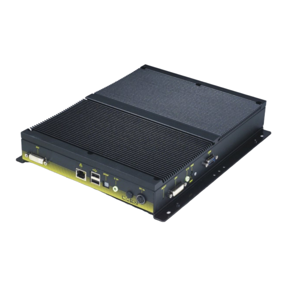
Physical Features Front panel Power LED NDiS 162 is designed for Digital Signage application. It provides ease of mounting the system behind large-size display devices such as LCD TV or PDP. NDiS 162 operates on AMD low power Athlon™ 64/64 X2 series proces- sors. -
Page 15: Hardware Specifications
• AMD M690E/M690T, AMD SB600 • SATA 2.5” HDD storage x1 • Integrated ATI X1270 graphic controller • u-DOC x1 • CF type I/II x1 (optional) Copyright © 2008 NEXCOM International Co., Ltd. All Rights Reserved. NDiS 162 User Manual... - Page 16 Operating temperature: Ambient with airflow from 0°C ~ 40°C (HDD inside) • Storage temperature: -20°C ~ 60°C, Humidity: 10% ~ 90% (non-con- densing) Certification • CE approval • Copyright © 2008 NEXCOM International Co., Ltd. All Rights Reserved. NDiS 162 User Manual...
-
Page 17: Mechanical Dimensions
Chapter 1: Product Introduction Mechanical Dimensions Copyright © 2008 NEXCOM International Co., Ltd. All Rights Reserved. NDiS 162 User Manual... -
Page 18: Chapter 2: Jumpers And Connectors
This chapter describes how to set the jumpers on the motherboard. Note tronic components. Humid environment tend to have less static electric- that the following procedures are generic for all NDiS 162 series. ity than dry environments. A grounding strap is warranted whenever danger of static electricity exists. -
Page 19: Jumper Settings
(on) and open (off). Two-Pin Jumpers: Open (Left) and Short (Right) Three-Pin Jumpers: Pins 1 and 2 Are Short Copyright © 2008 NEXCOM International Co., Ltd. All Rights Reserved. NDiS 162 User Manual... -
Page 20: Locations Of The Jumpers And Connectors
Locations of the Jumpers and Connectors NEX 662 The figure on the right is the NEX 662 motherboard which is the motherboard used in the NDiS 162 system. It shows the locations of the jumpers and connectors. Copyright © 2008 NEXCOM International Co., Ltd. All Rights Reserved. -
Page 21: Pin Definitions
DVI_TX4N DVI_TX4P CRT_CLK CRT_DATA CRT_VSYNC DVI_TX1N DVI_TX1P DVI_GND DVI_TX3N DVI_TX3P DVI_5V DVI_HPD DVI_TX0N DVI_TX0P DVI_GND DVI_TX5N DVI_TX5P DVI_GND DVI_CLKP DVI_CLKN MRED MGREEN MBLUE CRT_HSYNC VGA_GND VGA_GND Copyright © 2008 NEXCOM International Co., Ltd. All Rights Reserved. NDiS 162 User Manual... -
Page 22: Mini Pci Slot Cn10
CN10 PCIE_TX1+ USB_6N_L USB_6P_L +V3.3A_MINI +V3.3A_MINI LED_WLAN_N +V1.5S_MINI Definition Definition WAKE0# +V3.3_MINI +V3.3A_MINI +1.5S_MINI PCIE_MINI_CLKREQ#1 GPP_CLK1_N GPP_CLK1_P MINICARD1_DIS# PCIE_RST# PCIE_RX1- +V3.3A_MINI PCIE_RX1+ +V1.5S_MINI SMB1_CLK PCIE_TX1- SMB1_DAT Copyright © 2008 NEXCOM International Co., Ltd. All Rights Reserved. NDiS 162 User Manual... -
Page 23: S-Video Port Cn6
Chapter 2: Jumpers and Connectors S-Video Port S/PDIF Port Definition Definition Definition Definition GND_TV SPDIF_OUT_R GND_TV CP-Pr CP-Y Copyright © 2008 NEXCOM International Co., Ltd. All Rights Reserved. NDiS 162 User Manual... -
Page 24: Audio-Out Cn2
Connector size: 2 x 10 = 20 Pins Box Header, (2.0 mm Pitch) Connector location: COM1 (CN9), COM2 (CN8) Definition Definition Definition Definition LOUT_R3 SP_DCD_A SP_RXD_A SP_TXD_A SP_DTR_A LOUT_L3 SP_DSR_A SP_RTS_A SP_CTS_A SP_RI_A CON_GND Copyright © 2008 NEXCOM International Co., Ltd. All Rights Reserved. NDiS 162 User Manual... -
Page 25: Lan Cn5
LAN_ACTLED# LAN_LED1+ INTA# +5V_ATX DEVSEL# LAN_LED2- LAN_LED2+ INTC# INTB# STOP# +5V_ATX INTD# +3.3V_ATX LOCK# RSV1 PRSNT1# SMBCLK PERR# +3.3V_ATX RSV5 SMBDAT +3.3V_ATX RSV2 PRSNT2# SERR# +3.3V_ATX Copyright © 2008 NEXCOM International Co., Ltd. All Rights Reserved. NDiS 162 User Manual... -
Page 26: Usb Con1
AD28 +3.3V_ATX AD26 AD27 +3.3V AD25 AD24 +3.3V_ATX IDSEL C/BE2# +3.3V_ATX AD23 AD22 +3.3V_ATX +5V_ATX AD20 AD21 REQ64# ACK64# AD19 +5V_ATX +5V_ATX AD18 +3.3V_ATX +5V_ATX +5V_ATX Copyright © 2008 NEXCOM International Co., Ltd. All Rights Reserved. NDiS 162 User Manual... -
Page 27: Gpio J5
CN11 Definition Definition +5V_ATX GP23 GP32 GP22 GP31 GP21 GP30 GP20 GP24 Definition Definition +3.3V_ATX +3.3V_ATX +5V_ATX +5V_ATX SYS_PWRGD +5VALW_ATX +12V_ATX +3.3V_ATX -12V_ATX ATX_PSON +5V_ATX +5V_ATX Copyright © 2008 NEXCOM International Co., Ltd. All Rights Reserved. NDiS 162 User Manual... -
Page 28: Dc Power Con2
Chapter 2: Jumpers and Connectors DC Power CON2 Definition Definition MIC1_L3 AGND MIC1_R3 Definition Definition +12V_ATX +12V_ATX Definition Definition +5V_ATX CIRRX IR_RX IR_TX Copyright © 2008 NEXCOM International Co., Ltd. All Rights Reserved. NDiS 162 User Manual... -
Page 29: Keyboard/Mouse J6
GFX_TX1N LMCLK KBGND GFX_TX1P GFX_TX4N GFX_TX4P GFX_TX6N GFX_TX6P DVI_5V DVI2_HPD MASTER_RST# PWRBT_SW PWR_LED_P HD_LED_P +5V_ATX LINE1_OUT_L +5VALW_ATX LED_WLAN_P GFX_TX0N GFX_TX0P GFX_TX5N GFX_TX5P GFX_TX3N GFX_TX3P DVI_CLK DVI_DATA Copyright © 2008 NEXCOM International Co., Ltd. All Rights Reserved. NDiS 162 User Manual... -
Page 30: Smb J1
Chapter 2: Jumpers and Connectors SATA Definition Definition J8, J9 PWR_LED_N HD_LED_N +3.3V_ATX LINE1_OUT_R +3.3V_ATX LED_WLAN_N Definition Definition Definition SMB0_CLK SMB0_DAT Copyright © 2008 NEXCOM International Co., Ltd. All Rights Reserved. NDiS 162 User Manual... -
Page 31: Fan Connector Fan3
+12V_ATX SB600_FANTACH1 SB600_FANTACH0 SB600_FANOUT_R CMOS Input Voltage Select Fan Connector FAN2 Pin No. Status Function Description Short* VBAT IN Short Clear CMOS Definition Definition +12V_ATX SB600_FANTACH2 Copyright © 2008 NEXCOM International Co., Ltd. All Rights Reserved. NDiS 162 User Manual... -
Page 32: Mio02 Module
• Multi I/O port with pin-header for Audio output, Power-on / Storage LEDs, Power-on SW and Reset SW • DC out connector to DC/DC converter Connectors Copyright © 2008 NEXCOM International Co., Ltd. All Rights Reserved. NDiS 162 User Manual... -
Page 33: Pin Definitions
GFX_TX2N GFX_TX2P GFX_TX1N GFX_TX1P GFX_TX4N GFX_TX4P GFX_TX6N GFX_TX6P DVI_5V DVI2_HPD MASTER_RST# PWRBT_SW PWR_LED_P HD_LED_P +5V_ATX LINE1_OUT_L +5VALW_ATX LED_WLAN_P GFX_TX0N GFX_TX0P GFX_TX5N GFX_TX5P GFX_TX3N GFX_TX3P DVI_CLK DVI_DATA Copyright © 2008 NEXCOM International Co., Ltd. All Rights Reserved. NDiS 162 User Manual... -
Page 34: Audio Out Cn3
GFX _TX1N GFX _TX1P CON2 GFX _TX6N GFX _TX6P DVI_5V DVI_HPD GFX _TX2N GFX _TX2P GFX _TX4N GFX _TX4P GFX _TX3P GFX_TX3N Definition Definition +12V_ATX +12V_ATX Copyright © 2008 NEXCOM International Co., Ltd. All Rights Reserved. NDiS 162 User Manual... -
Page 35: Wlan Led Jp1
Chapter 2: Jumpers and Connectors WLAN LED Definition Definition LED_WLAN_N LED_WLAN_P Power In 12V Definition Definition VCC12V Copyright © 2008 NEXCOM International Co., Ltd. All Rights Reserved. NDiS 162 User Manual... -
Page 36: Chapter 3: System Setup
Remove screw 1. The screws on the cover are used to secure the cover to the chassis. Top View of the System Copyright © 2008 NEXCOM International Co., Ltd. All Rights Reserved. NDiS 162 User Manual... -
Page 37: Installing The Cpu
Make sure all power cables are unplugged before you install CAUTION! CAUTION! the CPU. • The CPU socket must not come in contact with anything other than the CPU. Avoid unnecessary exposure. CPU Socket Copyright © 2008 NEXCOM International Co., Ltd. All Rights Reserved. NDiS 162 User Manual... - Page 38 CPU will not fit in properly. below. Lever Pin 1 Pin 1 CPU Socket Handle the CPU by its edges and avoid touching the pins. Copyright © 2008 NEXCOM International Co., Ltd. All Rights Reserved. NDiS 162 User Manual...
- Page 39 Side Tab Do not force the CPU into the socket. Forcing the CPU into the CAUTION! CAUTION! socket may bend the pins and damage the CPU. Copyright © 2008 NEXCOM International Co., Ltd. All Rights Reserved. NDiS 162 User Manual...
-
Page 40: Installing A Dimm
Installing a DIMM 8. Replace the heat sink using the screws you removed earlier. The system board supports DDR2 533/667 DIMMs. When installing DIMMs, NEXCOM recommends using the same brand and type of memory modules. Locate the DIMM socket on the board. - Page 41 Push the module down. The ejector tabs at the ends of the socket will automatically snap into the locked position to hold the module in place. Notch Copyright © 2008 NEXCOM International Co., Ltd. All Rights Reserved. NDiS 162 User Manual...
-
Page 42: Installing A Sata Hard Drive
SATA drive with the mounting holes on the drive bay then use the provided screws to secure the drive in place. Copyright © 2008 NEXCOM International Co., Ltd. All Rights Reserved. NDiS 162 User Manual... -
Page 43: Installing A Compactflash Card (Optional)
1. The drive bay included in the package is used to hold the SATA-to-CF converter board. 6. Connect the SATA power cable to the power connector at the rear of the SATA drive. SATA power cable SATA data cable Copyright © 2008 NEXCOM International Co., Ltd. All Rights Reserved. NDiS 162 User Manual... - Page 44 2. Attach the 3 copper studs (posts) on the drive bay as shown in the il- 3. Place the SATA-to-CF converter board onto the drive bay then use the lustration below. provided screws to secure the board to the bay. Copyright © 2008 NEXCOM International Co., Ltd. All Rights Reserved. NDiS 162 User Manual...
-
Page 45: Installing The Wifi Module
Mini PCIe module slot 5. With the CompactFlash card’s label facing up, insert the CF card into the slot until it is completely seated in the slot. Copyright © 2008 NEXCOM International Co., Ltd. All Rights Reserved. NDiS 162 User Manual... - Page 46 3. Attach the other end of the cable to the WiFi antenna hole located at the side panel of the chassis. RF cable Internal view of the side panel Copyright © 2008 NEXCOM International Co., Ltd. All Rights Reserved. NDiS 162 User Manual...
- Page 47 5. The photo below shows the completed WiFi antenna setup. RF cable attached to the WiFi antenna hole Antenna RF cable attached to the WiFi Antenna module WiFi module Copyright © 2008 NEXCOM International Co., Ltd. All Rights Reserved. NDiS 162 User Manual...
-
Page 48: Replacing The Chassis Cover
Chapter 3: System Setup Replacing the Chassis Cover 2. Secure the cover to the chassis using the screws you removed earlier. 1. Replace the chassis cover. Remove screw Copyright © 2008 NEXCOM International Co., Ltd. All Rights Reserved. NDiS 162 User Manual... -
Page 49: Chapter 4: Driver Installation
1. Insert the provided CD into a CD-ROM drive. 2. Double-click the Setup file to install the driver. 3. Setup is now ready to install the driver. Click Next. Copyright © 2008 NEXCOM International Co., Ltd. All Rights Reserved. NDiS 162 User Manual... -
Page 50: Ati Display Driver
1. Insert the provided CD into a CD-ROM drive. 2. Double-click the Setup file to install the driver. 3. Setup is now ready to install the driver. Click Next. Copyright © 2008 NEXCOM International Co., Ltd. All Rights Reserved. NDiS 162 User Manual... - Page 51 Chapter 4: Driver Installation 4. Read the license agreement then click Yes. 5. Select the component you want to install then click Next. Copyright © 2008 NEXCOM International Co., Ltd. All Rights Reserved. NDiS 162 User Manual...
- Page 52 7. Setup has finished installing the selected components to your system. Click “Yes, I want to restart my computer now” then click Finish. Re- starting the system will allow the new driver installation to take effect. Copyright © 2008 NEXCOM International Co., Ltd. All Rights Reserved. NDiS 162 User Manual...
-
Page 53: Realtek Lan Driver
1. Insert the provided CD into a CD-ROM drive. 2. Double-click the Setup file to install the driver. 3. Setup is now ready to install the driver. Click Next. Copyright © 2008 NEXCOM International Co., Ltd. All Rights Reserved. NDiS 162 User Manual... -
Page 54: Idt Audio Driver
1. Insert the provided CD into a CD-ROM drive. 2. Double-click the Setup file to install the driver. 3. Setup is now ready to install the driver. Click Next. Copyright © 2008 NEXCOM International Co., Ltd. All Rights Reserved. NDiS 162 User Manual... - Page 55 5. Setup has finished installing the driver. Click “Yes, I want to restart my computer now” then click Finish. Restarting the system will allow the new driver installation to take effect. Copyright © 2008 NEXCOM International Co., Ltd. All Rights Reserved. NDiS 162 User Manual...
-
Page 56: Appendix A: Power Consumption
+5V and 5VSB +3.3V +12V Consumed watts 60.48 9.63 22.92 Consumed currents (Item A ) 12.1 1.96 1.91 Actually required currents (Item A/0.85 ) 14.24 2.31 2.24 Copyright © 2008 NEXCOM International Co., Ltd. All Rights Reserved. NDiS 162 User Manual...
Need help?
Do you have a question about the NDiS 162 and is the answer not in the manual?
Questions and answers