
Related Manuals for Nexcom NDiS 161


Summary of Contents for Nexcom NDiS 161
-
Page 1: User Manual
NEXCOM International Co., Ltd. Digital Signage Platform (MMS) NDiS 161 User Manual NEXCOM International Co., Ltd. www.nexcom.com Published October 2008... -
Page 2: Table Of Contents
KB/MS J3 ....................13 Overview of NDiS 161D2 ................3 COM1 CN1 ..................13 Key Features ..................4 COM2 CN2 ..................13 Physical Features ...................4 MIO Port CN14 ...................14 Hardware Specifications ................4 Copyright © 2008 NEXCOM International Co., Ltd. All Rights Reserved. NDiS 161 User Manual... - Page 3 Installing the WiFi Module ..............29 Replacing the Chassis Cover ..............32 Chapter 4: IEGD Driver Installation NDiS 161DV System Graphics Driver Installation ........33 NDiS 161D2 System Graphics Driver Installation ........36 Copyright © 2008 NEXCOM International Co., Ltd. All Rights Reserved. NDiS 161 User Manual...
-
Page 4: Preface
Acknowledgements The product(s) described in this manual complies with all applicable Euro- NDiS 161 is a trademark of NEXCOM International Co., Ltd. All other prod- pean Union (CE) directives if it has a CE marking. For computer systems to uct names mentioned herein are registered trademarks of their respective remain CE compliant, only CE-compliant parts may be used. -
Page 5: Rohs Compliance
0.1% or 1,000ppm, and Polybrominated diphenyl Ethers (PBDE) < 0.1% or 1,000ppm. In order to meet the RoHS compliant directives, NEXCOM has established an engineering and manufacturing task force in to implement the introduction of green products. The task force will ensure that we follow the standard... -
Page 6: Warranty And Rma
“NEXCOM RMA Service Form” for the RMA number apply process. Replace with 3rd party products if needed. If RMA goods can not be repaired, NEXCOM will return it to the customer Customers can send back the faulty products with or without accessories without any charge. -
Page 7: Safety Information
There is a danger of explosion if battery is incorrectly replaced. Replace Fax: +49-89-208039-279 only with the same or equivalent type recommended by the manufactur- http://www.nexcom.eu er. Discard used batteries according to the manufacturer’s instructions. Copyright © 2008 NEXCOM International Co., Ltd. All Rights Reserved. NDiS 161 User Manual... - Page 8 Tel: +86-10-5885-6655 Fax: +86-10-5885-1066 http://www.nexcom.cn China-Shanghai Office Room 2306, Silver Tower, No. 933 Zhongshan West Rd. Shanghai, Postcode 200051, China Tel: +86-21-6150-8008 Fax: +86-21-5111-3997 http://www.nexcom.cn viii Copyright © 2008 NEXCOM International Co., Ltd. All Rights Reserved. NDiS 161 User Manual...
-
Page 9: Technical Support And Assistance
Preface Technical Support and Assistance Installation Recommendations 1. For the most updated information of NEXCOM products, visit NEX- Ensure you have a stable, clean working environment. Dust and dirt can COM’s website at www.nexcom.com. get into components and cause a malfunction. Use containers to keep small components separated. -
Page 10: Safety Precautions
11. All cautions and warnings on the equipment should be noted. 19. The computer is provided with CD drives that comply with the ap- propriate safety standards including IEC 60825. Copyright © 2008 NEXCOM International Co., Ltd. All Rights Reserved. NDiS 161 User Manual... - Page 11 Preface ackage ontents Before continuing, verify that the NDiS 161 package that you received is complete. Your NDiS 161 package should have all the items listed in the following table. Item Name 50311F0100X00 ROUND HEAD SCREW W/SPRING+FLAT WASHER LONG FEI:P3x6L 60233DVI18X00 DVI-I to DVI-D &...
-
Page 12: Conventions Used In This Manual
Core 2 Duo, Core Duo, Celeron ® M fan-less barebone system data. - Intel ® 945GME/ICH7M with CRT/DVI/TV Note: Provides additional information to complete a task easily. Copyright © 2008 NEXCOM International Co., Ltd. All Rights Reserved. NDiS 161 User Manual... -
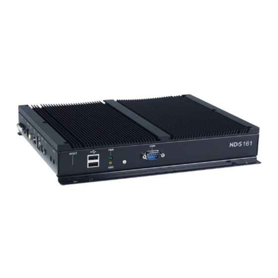
Page 13: Chapter 1: Product Introduction
NDiS 161DV provides DVI and VGA display interfaces, one GbE Ethernet with optional wireless connectivity, USB 2.0 ports and a 2.5” drive bay for Reset button storage devices. Power button Copyright © 2008 NEXCOM International Co., Ltd. All Rights Reserved. NDiS 161 User Manual... -
Page 14: Hardware Specifications
M 423 Storage Chipset • SATA 2.5” HDD storage x1 • Intel ® 945GME • u-DOC x1 • Intel ICH7-M • CF type I/II x1 (optional) ® Copyright © 2008 NEXCOM International Co., Ltd. All Rights Reserved. NDiS 161 User Manual... -
Page 15: Overview Of Ndis 161D2
NDiS 161D2 provides DVI and VGA display interfaces, one GbE Ethernet Certification with optional wireless connectivity, USB 2.0 ports and a 2.5” drive bay for • CE approval storage devices. • Copyright © 2008 NEXCOM International Co., Ltd. All Rights Reserved. NDiS 161 User Manual... -
Page 16: Key Features
- Core™ 2 Duo L7400 Reset - Core™ Duo L2400, U2500 button - Celeron ® M 423 Power button Chipset • Intel ® 945GME • Intel ICH7-M ® Copyright © 2008 NEXCOM International Co., Ltd. All Rights Reserved. NDiS 161 User Manual... - Page 17 Optional antenna for WiFi x1 • +12V DC-in power x1 Storage • SATA 2.5” HDD storage x1 • u-DOC x1 • CF type I/II x1 (optional) Copyright © 2008 NEXCOM International Co., Ltd. All Rights Reserved. NDiS 161 User Manual...
-
Page 18: Mechanical Dimensions
Chapter 1: Product Introduction Mechanical Dimensions NDiS 161DV Copyright © 2008 NEXCOM International Co., Ltd. All Rights Reserved. NDiS 161 User Manual... -
Page 19: Ndis 161D2
Chapter 1: Product Introduction NDiS 161D2 Copyright © 2008 NEXCOM International Co., Ltd. All Rights Reserved. NDiS 161 User Manual... -
Page 20: Chapter 2: Jumpers And Connectors
This chapter describes how to set the jumpers on the NDiS 161 board. tronic components. Humid environment tend to have less static electric- Note that the following procedures are generic for all NDiS 161 series. ity than dry environments. A grounding strap is warranted whenever danger of static electricity exists. -
Page 21: Jumper Settings
(on) and open (off). Two-Pin Jumpers: Open (Left) and Short (Right) Three-Pin Jumpers: Pins 1 and 2 Are Short Copyright © 2008 NEXCOM International Co., Ltd. All Rights Reserved. NDiS 161 User Manual... -
Page 22: Locations Of The Jumpers And Connectors
Chapter 2: Jumpers and Connectors Locations of the Jumpers and Connectors The following figure is the board used in the NDiS 161 system. It shows the locations of the jumpers and connectors. Copyright © 2008 NEXCOM International Co., Ltd. All Rights Reserved. -
Page 23: Pin Definitions
VCC5 Signal CIRRX 3VSB IRRX SMB_CLK_RESUME SMB_DATA_RESUME IRTX GPIO Mic-in Signal Signal Signal VCC5 MIC1 _L3 SIO_GP20 SIO_GP24 SIO_GP21 SIO_GP25 SIO_GP22 SIO_GP26 MIC3 R3 SIO_GP23 SIO_GP27 Copyright © 2008 NEXCOM International Co., Ltd. All Rights Reserved. NDiS 161 User Manual... -
Page 24: Com2 Rs232 Ri# Power Select Jp1
SP_RI2_T USB_OC23# SP_RI2 CCFL LVDS Power Control Signal Description VCC5 VCC5_PANEL1 PANEL1_BACKLIGHT 2-3* VCC3_ PANEL1 PANEL1_BACKLIGHT L_BKLTCTL ATX Power Description L_BKLTEN AT MODULE 2-3* ATX MODULE Copyright © 2008 NEXCOM International Co., Ltd. All Rights Reserved. NDiS 161 User Manual... -
Page 25: Audio J11
SP_RTS1 SP_CTS1 LOUT_L3 SP_RI1 GND_SP KB/MS COM2 Signal Signal Signal K/M_VCC SP_DCD2 SP_RXD2 LKBDAT SP_TXD SP_TDR2 LKBCLK GND_SP SP_DSR2 LMDAT SP_RTS2 SP_CTS2 LMCLK SP_RI2 GND_SP KBGND Copyright © 2008 NEXCOM International Co., Ltd. All Rights Reserved. NDiS 161 User Manual... -
Page 26: Mio Port Cn14
PANEL1_VDD LA_DATAP0 VCC5 USB_OC45 LA_DATAN0 PANEL1_VDD CPU Fan LVDS_GND LA_DATAP1 LA_CLKP LA_DATAN1 Signal LA_CLKN LVDS_GND LVDS_GND PANEL1_BACK- LIGHT +12V LA_DATAP2 PANEL1_BACK- VCC5 LIGHT CPU_FAN_J LA_DATAN2 LVDS_GND Copyright © 2008 NEXCOM International Co., Ltd. All Rights Reserved. NDiS 161 User Manual... -
Page 27: Sata0 J6
ATX Power CN10 Description TXP0 Description Description TXN0 +3.3V +3.3V +3.3V -12V RXN0 RXP0 Power On SATA1 Power OK Description +5VSB +12V TXP1 TXN1 RXN1 RXP1 Copyright © 2008 NEXCOM International Co., Ltd. All Rights Reserved. NDiS 161 User Manual... -
Page 28: Pci Cn13
SMB_CLK_MAIN PCI_PERR# VCC5 PCI_CLK0 SMB_DATA_ VCC3 MAIN PCI_GNT#0 PCI_SERR# PCI_REQ#0 PCI_PAR VCC3 PCI_PME# VCC5 PCI_AD15 PCI_CBE#1 PCI_AD30 PCI_AD31 VCC3 PCI_AD14 VCC3 PCI_AD29 PCI_AD13 PCI_AD28 PCI_AD26 PCI_AD27 Copyright © 2008 NEXCOM International Co., Ltd. All Rights Reserved. NDiS 161 User Manual... -
Page 29: Usb Port 0/1 Cn8
PCI_AD2 LAN_ACTLED# 3VSB PCI_AD0 PCI_AD1 LAN_L100# LAN1_L1000# VCC5 VCC5 GND_CAS GND_CAS VCC5 VCC5 USB Port 0/1 Description Description USB_0N USB_1N USB_0P USB_1P GND_CAS GND_CAS GND_CAS GND_CAS Copyright © 2008 NEXCOM International Co., Ltd. All Rights Reserved. NDiS 161 User Manual... -
Page 30: Mini Pcie Cn11
+V1.5S_MINI SMB_CLK_RE- SUME PET_N1 SMB_DATA_ REAUME PET_P1 USB_6N USB_6P +V3.3A_MINI +V3.3A_MINI LED_WLAN_N Signal Signal PCIE_WAKE# +V3.3A_MINI +V1.5S_MINI +V1.5S_MINI +V3.3A_MINI PCIE_MINI_ CLKREQ#1 CK_MPCIE_N CK_MPCIE_P MINICARD1_ DIS# PLT_RST_BUF# Copyright © 2008 NEXCOM International Co., Ltd. All Rights Reserved. NDiS 161 User Manual... -
Page 31: Line-Out Cn12
S-Video Signal Signal Signal Signal TDC_2# TDC_2 GND_TV_CAS CP_Pb GND_TV GND_TV DVI_DDC_C CP_Pr CP_Y DVI_DDC_D VS_VGA GND_CAS GND_CAS TDC_1# TDC_1 DVI_VCC HPDET TDC_0# TDC_0 CLK_V DATA_V Copyright © 2008 NEXCOM International Co., Ltd. All Rights Reserved. NDiS 161 User Manual... -
Page 32: S/Pdif Cn9
GND_CAS GND_CAS SDVOB_G S/PDIF SDVOB_G# SDVOB_B SDVOB_B# Signal Signal SDVO_CTRL- P3V3_OPTIC SDVO_CTRL- PLT_RST_BUF2 SPDIF_OUT GND_CAS DATA GND_CAS SDVOB_CLKP SDVOB_CLKN VCC3 VCC3 VCC3 VCC3 +12V +12V +12V Copyright © 2008 NEXCOM International Co., Ltd. All Rights Reserved. NDiS 161 User Manual... -
Page 33: Chapter 3: System Setup
1. The screws on the cover are used to secure the cover to the chassis. Remove screw Top View of the System Copyright © 2008 NEXCOM International Co., Ltd. All Rights Reserved. NDiS 161 User Manual... -
Page 34: Installing The Cpu
The CPU socket must not come in contact with anything other Handle the CPU by its edges and avoid touching the pins. than the CPU. Avoid unnecessary exposure. Copyright © 2008 NEXCOM International Co., Ltd. All Rights Reserved. NDiS 161 User Manual... - Page 35 The CPU will fit in only one orientation and can easily be inserted without exerting any force. Pin 1 of the socket Copyright © 2008 NEXCOM International Co., Ltd. All Rights Reserved. NDiS 161 User Manual...
-
Page 36: Installing A Dimm
Installing a DIMM 7. Replace the heat sink using the screws you removed earlier. The system board supports DDR2 533/667 DIMMs. When installing DIMMs, NEXCOM recommends using the same brand and type of memory modules. Locate the DIMM socket on the board. - Page 37 Push the module down. The ejector tabs at the ends of the socket will automatically snap into the locked position to hold the module in place. Notch Copyright © 2008 NEXCOM International Co., Ltd. All Rights Reserved. NDiS 161 User Manual...
-
Page 38: Installing A Sata Hard Drive
SATA drive with the mounting holes on the drive bay then use the provided screws to secure the drive in place. Copyright © 2008 NEXCOM International Co., Ltd. All Rights Reserved. NDiS 161 User Manual... -
Page 39: Installing A Compactflash Card (Optional)
1. The drive bay included in the package is used to hold the SATA-to-CF converter board. 6. Connect the SATA power cable to the power connector at the rear of the SATA drive. SATA power cable SATA data cable Copyright © 2008 NEXCOM International Co., Ltd. All Rights Reserved. NDiS 161 User Manual... - Page 40 2. Attach the 3 copper studs (posts) on the drive bay as shown in the il- 3. Place the SATA-to-CF converter board onto the drive bay then use the lustration below. provided screws to secure the board to the bay. Copyright © 2008 NEXCOM International Co., Ltd. All Rights Reserved. NDiS 161 User Manual...
-
Page 41: Installing The Wifi Module
Mini PCIe module slot 5. With the CompactFlash card’s label facing up, insert the CF card into the slot until it is completely seated in the slot. Copyright © 2008 NEXCOM International Co., Ltd. All Rights Reserved. NDiS 161 User Manual... - Page 42 3. Attach the other end of the cable to the WiFi antenna hole located at the side panel of the chassis. RF cable Internal view of the side panel Copyright © 2008 NEXCOM International Co., Ltd. All Rights Reserved. NDiS 161 User Manual...
- Page 43 5. The photo below shows the completed WiFi antenna setup. RF cable attached to the WiFi antenna hole Antenna RF cable attached to the WiFi Antenna module WiFi module Copyright © 2008 NEXCOM International Co., Ltd. All Rights Reserved. NDiS 161 User Manual...
-
Page 44: Replacing The Chassis Cover
Chapter 3: System Setup Replacing the Chassis Cover 2. Secure the cover to the chassis using the screws you removed earlier. 1. Replace the chassis cover. Replace screw Copyright © 2008 NEXCOM International Co., Ltd. All Rights Reserved. NDiS 161 User Manual... -
Page 45: Chapter 4: Iegd Driver Installation
Select “Installs driver and application files” then click Next. existing graphics drivers. When you reboot the system, in Device Manager, yellow mark will ap- pear next to the Video Controller. Copyright © 2008 NEXCOM International Co., Ltd. All Rights Reserved. NDiS 161 User Manual... - Page 46 Chapter 4: IEGD Driver Installation 4. After completing installation, click Yes to restart the computer. 5. Device Manager is now able to detect the dual display graphics device. Copyright © 2008 NEXCOM International Co., Ltd. All Rights Reserved. NDiS 161 User Manual...
- Page 47 Display in Control Panel. first see the General tab. Select the Display Config tab. In the Display Properties dialog box, select the Settings tab then click Advanced. Copyright © 2008 NEXCOM International Co., Ltd. All Rights Reserved. NDiS 161 User Manual...
-
Page 48: Ndis 161D2 System Graphics Driver Installation
1. Prior to installing the dual display driver, make sure to first uninstall any existing graphics drivers. When you reboot the system, in Device Manager, yellow mark will ap- pear next to the Video Controller. Copyright © 2008 NEXCOM International Co., Ltd. All Rights Reserved. NDiS 161 User Manual... - Page 49 4. After completing installation, click Yes to restart the computer. 3. In the “VGA\Dual_DVI” folder, double-click the Setup file to install the driver. Select “Installs driver and application files” then click Next. Copyright © 2008 NEXCOM International Co., Ltd. All Rights Reserved. NDiS 161 User Manual...
- Page 50 6. On your desktop, right-click your mouse then select Properties. You can also double-click Display in Control Panel. In the Display Properties dialog box, select the Settings tab then click Advanced. Copyright © 2008 NEXCOM International Co., Ltd. All Rights Reserved. NDiS 161 User Manual...
- Page 51 7. In the Plug and Play Monitor and Intel Corporation dialog box, you will 8. Under the Display Configuration section, select SDVO_C (clone) TVOUT first see the General tab. Select the Display Config tab. then click OK. Copyright © 2008 NEXCOM International Co., Ltd. All Rights Reserved. NDiS 161 User Manual...
Need help?
Do you have a question about the NDiS 161 and is the answer not in the manual?
Questions and answers