
Related Manuals for Nexcom NDIS M537


Summary of Contents for Nexcom NDIS M537
- Page 1 NEXCOM International Co., Ltd. Intelligent Platform & Services Business Unit Digital Signage Platform NDiS M537 User Manual NEXCOM International Co., Ltd. www.nexcom.com Published September 2018...
-
Page 2: Table Of Contents
Rear Panel ...................2 Fan Connector ................16 Hardware Specifications ................3 Debug 80 Port Connector ..............17 Mechanical Dimensions ................4 M.2 E Key Connector ..............18 M.2 M Key Connector ..............19 Copyright © 2018 NEXCOM International Co., Ltd. All Rights Reserved. NDiS M537 User Manual... - Page 3 Legends ....................34 BIOS Setup Utility ..................36 Main ....................36 Advanced ..................37 Chipset ....................45 Security .....................46 Boot ....................46 Save & Exit ..................47 Appendix A: Watchdog Programming Guide ..48 Copyright © 2018 NEXCOM International Co., Ltd. All Rights Reserved. NDiS M537 User Manual...
-
Page 4: Preface
No describes how to keep the system CE compliant. part of this manual may be reproduced, copied, translated or transmitted in any form or by any means without the prior written consent from NEXCOM Declaration of Conformity International Co., Ltd. -
Page 5: Rohs Compliance
(Cr6+) < 0.1% or 1,000ppm, Polybrominated biphenyls (PBB) < 0.1% or 1,000ppm, and Polybrominated diphenyl Ethers (PBDE) < 0.1% or 1,000ppm. In order to meet the RoHS compliant directives, NEXCOM has established an engineering and manufacturing task force to implement the introduction of green products. -
Page 6: Warranty And Rma
(manuals, cable, etc.) and any components from the card, such as CPU and RAM. If the components were suspected as part of the problems, ▪ If RMA goods can not be repaired, NEXCOM will return it to the customer please note clearly which components are included. Otherwise, NEXCOM without any charge. - Page 7 ESD workstation. If no such station is available, you can provide some ESD protection by wearing an antistatic wrist strap and attaching it to a metal part of the computer chassis. Copyright © 2018 NEXCOM International Co., Ltd. All Rights Reserved. NDiS M537 User Manual...
-
Page 8: Safety Information
There is a danger of explosion if battery is incorrectly replaced. Replace only with the same or equivalent type recommended by the manufacturer. Discard used batteries according to the manufacturer’s instructions. viii Copyright © 2018 NEXCOM International Co., Ltd. All Rights Reserved. NDiS M537 User Manual... -
Page 9: Safety Precautions
RECOMMENDED BY THE MANUFACTURER. DISCARD USED BATTERIES ACCORDING TO THE MANUFACTURER’S INSTRUCTIONS. 10. All cautions and warnings on the equipment should be noted. Copyright © 2018 NEXCOM International Co., Ltd. All Rights Reserved. NDiS M537 User Manual... -
Page 10: Technical Support And Assistance
Preface Technical Support and Assistance Conventions Used in this Manual 1. For the most updated information of NEXCOM products, visit NEXCOM’s Warning: website at www.nexcom.com. Information about certain situations, which if not observed, can cause personal injury. This will prevent injury to yourself 2. -
Page 11: Global Service Contact Information
13F, No.920, Chung-Cheng Rd., ZhongHe District, Beijing, 100094, China New Taipei City, 23586, Taiwan, R.O.C. Tel: +86-10-5704-2680 Tel: +886-2-8226-7796 Fax: +86-10-5704-2681 Fax: +886-2-8226-7792 Email: sales@nexcom.cn Email: sales@nexcom.com.tw www.nexcom.cn www.nexcom.com.tw Copyright © 2018 NEXCOM International Co., Ltd. All Rights Reserved. NDiS M537 User Manual... - Page 12 Hui Yin Ming Zun Building Room 1108, Building No. 11, 599 Yunling Road, Putuo District, Shanghai, 200062, China Tel: +86-21-6125-8282 Fax: +86-21-6125-8281 Email: frankyang@nexcom.cn www.nexcom.cn Copyright © 2018 NEXCOM International Co., Ltd. All Rights Reserved. NDiS M537 User Manual...
-
Page 13: Package Contents
Preface Package Contents Before continuing, verify that the NDiS M537 package that you received is complete. Your package should have all the items listed in the following table. Item Part Number Name Description 50311F0111X00 Flat Head Screw Long Fei:F3x5ISO+Nylok Black... -
Page 14: Ordering Information
Preface Ordering Information The following below provides ordering information for NDiS M537. NDiS M537 (P/N: 10W00M53700X0) 7th/6th generation Intel Core™ LGA1151 type processor OPS PLUS, Intel ® ® Q170 chipset Copyright © 2018 NEXCOM International Co., Ltd. All Rights Reserved. -
Page 15: Chapter 1: Product Introduction
Core™ processors. Following open pluggable standard, ® NDiS M537 can perfectly fit into a myriad of OPS PLUS-panels and is compact in size. Yet, NDiS M537 has high scalability, allowing for easy storage capacity expansion through pluggable M.2 storage unit and effortless functional extension through FX18-60P (PCIe x4, DP1.2) expansion modules. -
Page 16: Physical Features
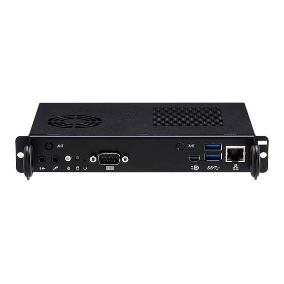
Physical Features Front Panel Rear Panel Antenna Hole Antenna Hole USB 3.0 Line-out Mini HRS FX18 60Pin JAE TX25 80Pin DisplayPort Mic-in Power Reset Button Button Storage Copyright © 2018 NEXCOM International Co., Ltd. All Rights Reserved. NDiS M537 User Manual... -
Page 17: Hardware Specifications
Core™: Windows 10 (64-bit) ® ▪ 1 x UART (3.3V TTL) (COM2) ▪ 6th generation Intel Core™: Windows 7 (32/64-bit)/Windows 10 (64-bit) ® ▪ 1 x Audio out L/R Copyright © 2018 NEXCOM International Co., Ltd. All Rights Reserved. NDiS M537 User Manual... -
Page 18: Mechanical Dimensions
Chapter 1: Product Introduction Mechanical Dimensions 180 ±0.40 200 ±0.40 Copyright © 2018 NEXCOM International Co., Ltd. All Rights Reserved. NDiS M537 User Manual... -
Page 19: Chapter 2: Jumpers And Connectors
Static electricity can damage many of the electronic ▪ Use correct screws and do not over tighten screws. components. Humid environments tend to have less static electricity than Copyright © 2018 NEXCOM International Co., Ltd. All Rights Reserved. NDiS M537 User Manual... -
Page 20: Locations Of The Jumpers And Connectors For Ndib M537
Locations of the Jumpers and Connectors for NDiB M537 The figure below is the top and bottom view of the NDiB M537 mainboard which is the mainboard used in NDiS M537. It shows the locations of the jumpers and connectors. -
Page 21: Bottom View
Chapter 2: Jumpers and Connectors Bottom View Copyright © 2018 NEXCOM International Co., Ltd. All Rights Reserved. NDiS M537 User Manual... -
Page 22: Jumper Settings
(on) and open (off). Two-Pin Jumpers: Open (Left) and Short (Right) Three-Pin Jumpers: Pins 1 and 2 are Short Copyright © 2018 NEXCOM International Co., Ltd. All Rights Reserved. NDiS M537 User Manual... -
Page 23: Jumpers
RTC Clear Jump Connector type: 1x3 3-pin header, 2.54mm pitch, MALE 180D Connector location: JP1 Settings 1-2 On Normal 2-3 On Clear CMOS 1-2 On: default Copyright © 2018 NEXCOM International Co., Ltd. All Rights Reserved. NDiS M537 User Manual... -
Page 24: Connector Pin Definitions
Chapter 2: Jumpers and Connectors Connector Pin Definitions External I/O Interfaces Power Switch System Reset Switch Connector location: SW1 Connector location: SW2 Power LED Definition Definition Blue System Reset Copyright © 2018 NEXCOM International Co., Ltd. All Rights Reserved. NDiS M537 User Manual... -
Page 25: Lan Connector
TD3- USB0_P TD3+ TD2- USB3_RX0_N USB3_RX0_P TD2+ TD1- USB3_TX0_N TD1+ TCTG USB3_TX0_P Left_LED+ Left_LED- USB1_N USB1_P Right_LED+ Right_LED- USB3_RX1_N Left-LED: Link/Active:Green Right-LED: 1G/100:Green/Orange USB3_RX1_P USB3_TX1_N USB3_TX1_P Copyright © 2018 NEXCOM International Co., Ltd. All Rights Reserved. NDiS M537 User Manual... -
Page 26: Mini Displayport Connector
Connector location: CN7 Definition Definition LED Definition PWR_IN HPD_GND Yellow TBT_HD2CA_0+ TBT_CA2HD_0+ TBT_HD2CA_0- TBT_CA2HD_0- GND1 GND2 LSTX RESERVED1 LSRX RESERVED2 GND3 GND4 TBT_HD2CA_1+ TBT_CA2HD_1+ TBT_HD2CA_1- TBT_CA2HD_1- RETURN PWR_OUT Copyright © 2018 NEXCOM International Co., Ltd. All Rights Reserved. NDiS M537 User Manual... -
Page 27: Mic-In Connector
Mic-in Connector Line-out Connector Connector type: 3.5mm TRS Connector type: 3.5mm TRS Connector location: CN4 Connector location: CN5 Definition Definition Definition Definition IN/OUT_R IN/OUT_R IN/OUT_L IN/OUT_L Copyright © 2018 NEXCOM International Co., Ltd. All Rights Reserved. NDiS M537 User Manual... -
Page 28: Jae-Tx25 Connector
DDP_1P HDMI0_TX2N SYS_FAN_EN# 46 PS_ON# 19 DDP_0N HDMI0_TX2P COM1_RXD 46 PWR_STATUS DDP_0P COM1_TXD 46 HDMI0_SDA DDP_AUXN HDMI0_SCL USB_RX2N DDP_AUXP HDMI0_HPD USB_RX2P DDP_HPD VIN_M USB_TX2N HDMI0_CLK_N VIN_M Copyright © 2018 NEXCOM International Co., Ltd. All Rights Reserved. NDiS M537 User Manual... -
Page 29: Hrs-Fx18-60S Connector
I2C1_CLK LAN_DISABLE PCIE-RXP1 I2C1_DATA1 SLEEP_S3 PCIE-TXN1 PICe_RST DDP1_AUNX PCIE-TXP1 GPIO PCIE-RXN2 DDP1_AUNP PCIE-RXP2 DDP1_3N DDP1_1N PCIE-TXN2 DDP1_3P DDP1_1P PCIE-TXP2 PCIE-RXN3 DDP1_2N PCIE-RXP3 DDP1_0N DDP1_2P DDP1_0P PCIE-TXN3 Copyright © 2018 NEXCOM International Co., Ltd. All Rights Reserved. NDiS M537 User Manual... -
Page 30: Internal Connectors
RTC Battery Connector Fan Connector Connector type: 1x2 2-pin header Connector type: 1x4 4-pin header Connector location: J4 Connector location: J2 Definition Definition Definition SPEED CONTROL Copyright © 2018 NEXCOM International Co., Ltd. All Rights Reserved. NDiS M537 User Manual... -
Page 31: Debug 80 Port Connector
Chapter 2: Jumpers and Connectors Debug 80 Port Connector Connector type: 1x10 10-pin header Connector location: J5 Definition Definition PCIRST# 33M_CLK LPC_FRAME# LPC_AD3 LPC_AD2 LPC_AD1 LPC_AD0 3.3V 3.3V Copyright © 2018 NEXCOM International Co., Ltd. All Rights Reserved. NDiS M537 User Manual... -
Page 32: M.2 E Key Connector
PETp1 I2C_DATA SOIO_DATA PETn1 I2C_CLK SOIO_WAKE# WAKE ALERT SOIO_RESET# PERp1 RESERVED HW Latch PERn1 PERST CLKREQ PETp0 REFCLKp1 PEWAKE PETn0 REFCLKn1 3.3V VENDOR 3.3V PERp0 VENDOR Copyright © 2018 NEXCOM International Co., Ltd. All Rights Reserved. NDiS M537 User Manual... -
Page 33: M.2 M Key Connector
PEWAKE PERP2 REFCLKP NC16 GND5 GND11 NC17 PETN2 HW Latch PETP2 NC26 SUSCLK GND6 PEDET 3.3V_3 PERN1 GND12 3.3V_4 PERP1 GND13 3.3V_5 GND7 GND14 PETN1 NC10 Copyright © 2018 NEXCOM International Co., Ltd. All Rights Reserved. NDiS M537 User Manual... -
Page 34: Chapter 3: System Setup
2. With the screws removed, push back the cover and remove it from the Remove these screws and put them in a safe place for later use. chassis. Screws on the back Copyright © 2018 NEXCOM International Co., Ltd. All Rights Reserved. NDiS M537 User Manual... -
Page 35: Installing The Cpu (Socket Type)
1. Remove the chassis cover, then loosen all the five screws and unplug the fan power connector to remove the cooler and access the CPU socket. Screw Copyright © 2018 NEXCOM International Co., Ltd. All Rights Reserved. NDiS M537 User Manual... - Page 36 ▪ Handle the CPU by its edges and avoid touching the pins. CAUTION! CAUTION! ▪ The CPU will fit in only one orientation and can easily be CAUTION! inserted without exerting any force. Copyright © 2018 NEXCOM International Co., Ltd. All Rights Reserved. NDiS M537 User Manual...
- Page 37 Please install the thermal pad and make sure the adhesive CAUTION! CAUTION! CAUTION! film on the thermal pad is removed before placing it on the heat sink. Copyright © 2018 NEXCOM International Co., Ltd. All Rights Reserved. NDiS M537 User Manual...
- Page 38 Chapter 3: System Setup 6. Put the cooler back to its original location and apply all the five screws and fan power connector to secure it in place. Copyright © 2018 NEXCOM International Co., Ltd. All Rights Reserved. NDiS M537 User Manual...
-
Page 39: Installing A So-Dimm Memory Module
Chapter 3: System Setup Installing a SO-DIMM Memory Module 1. There are two SO-DIMM sockets in NDiS M537. One is on the top side 2. Push the ejector tabs which are at the ends of the socket outward. This and the another is on the bottom. With the chassis cover and cooler indicates that the socket is unlocked. - Page 40 The ejector tabs at the ends of the socket will automatically snap into the locked position to hold the module in place. Copyright © 2018 NEXCOM International Co., Ltd. All Rights Reserved. NDiS M537 User Manual...
- Page 41 Chapter 3: System Setup 5. Follow the instructions in step 2 and step 3 above to install the memory module. DIMM1 Copyright © 2018 NEXCOM International Co., Ltd. All Rights Reserved. NDiS M537 User Manual...
-
Page 42: Installing An M.2 Ssd Storage Module
1. At the bottom of the system, loosen the screws on the bottom cover, then remove the cover from the chassis. M.2 M Key Slot Copyright © 2018 NEXCOM International Co., Ltd. All Rights Reserved. NDiS M537 User Manual... - Page 43 3. With the module fully inserted, tighten a screw into the mounting hole on the module to secure it. Screw Copyright © 2018 NEXCOM International Co., Ltd. All Rights Reserved. NDiS M537 User Manual...
-
Page 44: Installing A Wireless Lan Module
2. Insert the Wi-Fi module into the M.2 E key slot at a 45 degree angle mainboard. until the gold-plated connector on the edge of the module completely disappears inside the slot. M.2 E Key Slot Copyright © 2018 NEXCOM International Co., Ltd. All Rights Reserved. NDiS M537 User Manual... - Page 45 4. Attach the RF cables onto the Wi-Fi module and insert the antenna jack on the module to secure it. end of the cable through the antenna hole. Screw RF Cable Copyright © 2018 NEXCOM International Co., Ltd. All Rights Reserved. NDiS M537 User Manual...
- Page 46 5. Insert the 2 rings (ring 1 then ring 2) into the Wi-Fi antenna jacks. 6. Connect the external antennas to the Wi-Fi antenna jacks. Ring1 Ring2 Antenna Copyright © 2018 NEXCOM International Co., Ltd. All Rights Reserved. NDiS M537 User Manual...
-
Page 47: Chapter 4: Bios Setup
This chapter describes how to use the BIOS setup program for NDiS M537. The settings made in the setup program affect how the computer performs. The BIOS screens provided in this chapter are for reference only and may It is important, therefore, first to try to understand all the setup options, and change if the BIOS is updated in the future. -
Page 48: Default Configuration
Powering on the computer and immediately pressing <Del> allows you to enter Setup. Load optimized default values. Press the key to enter Setup: Saves and exits the Setup program. Press <Enter> to enter the highlighted sub-menu Copyright © 2018 NEXCOM International Co., Ltd. All Rights Reserved. NDiS M537 User Manual... - Page 49 When “” appears on the left of a particular field, it indicates that a submenu which contains additional options are available for that field. To display the submenu, move the highlight to that field and press Copyright © 2018 NEXCOM International Co., Ltd. All Rights Reserved. NDiS M537 User Manual...
-
Page 50: Bios Setup Utility
00 to 23. Minute displays minutes from 00 to 59. Second displays seconds from 00 to 59. Version 2.18.1263. Copyright (C) 2018 American Megatrends, Inc. Copyright © 2018 NEXCOM International Co., Ltd. All Rights Reserved. NDiS M537 User Manual... -
Page 51: Advanced
State After G3 CPU C States Configures the power state when power is re-applied after a power failure Enables or disables CPU C states. (G3 state). Copyright © 2018 NEXCOM International Co., Ltd. All Rights Reserved. NDiS M537 User Manual... - Page 52 (Advanced Host Controller Interface). AHCI allows the storage driver to enable the advanced Serial ATA features which will increase storage performance. SATA Test Mode Enables or disables SATA test mode. Copyright © 2018 NEXCOM International Co., Ltd. All Rights Reserved. NDiS M537 User Manual...
- Page 53 Enables or disables BIOS support for security device. O.S will not show Security Device. TCG EFI protocol and INT1A interface will not be available. MEBx Selection Screen Enables or disables MEBx selection screen. Copyright © 2018 NEXCOM International Co., Ltd. All Rights Reserved. NDiS M537 User Manual...
- Page 54 Select the highest ACPI sleep state the system will enter when the suspend button is pressed. The options are Suspend Disabled and S3 (Suspend to RAM). Copyright © 2018 NEXCOM International Co., Ltd. All Rights Reserved. NDiS M537 User Manual...
- Page 55 Displays the IO address and IRQ of the front serial COM port. Change Settings Change Settings Selects an optimal setting for the Super IO device. Selects an optimal setting for the Super IO device. Copyright © 2018 NEXCOM International Co., Ltd. All Rights Reserved. NDiS M537 User Manual...
- Page 56 When DynamicTime is selected, system will wake on the current time + Increase minute(s). System Fan Mode Configures the operating mode of the system fan. Copyright © 2018 NEXCOM International Co., Ltd. All Rights Reserved. NDiS M537 User Manual...
- Page 57 Enables or disables Compatibility Support Module (CSM). Boot Option Filter This option filters which devices the system can boot to. Network Enables or disables the boot option for legacy network devices. Copyright © 2018 NEXCOM International Co., Ltd. All Rights Reserved. NDiS M537 User Manual...
- Page 58 Disabled Keeps USB devices available only for EFI applications. XHCI Hand-off This is a workaround for OSs that does not support XHCI hand-off. The XHCI ownership change should be claimed by the XHCI driver. Copyright © 2018 NEXCOM International Co., Ltd. All Rights Reserved. NDiS M537 User Manual...
-
Page 59: Chipset
Version 2.18.1263. Copyright (C) 2018 American Megatrends, Inc. Graphics Configuration Enters the Graphics Configuration submenu. Version 2.18.1263. Copyright (C) 2018 American Megatrends, Inc. System Agent (SA) Configuration System Agent (SA) parameters. Copyright © 2018 NEXCOM International Co., Ltd. All Rights Reserved. NDiS M537 User Manual... -
Page 60: Security
This allows you to adjust the boot sequence of the system. Boot Option #1 is the first boot device that the system will boot from, next will be #2 and so forth. Copyright © 2018 NEXCOM International Co., Ltd. All Rights Reserved. NDiS M537 User Manual... -
Page 61: Save & Exit
<Enter>. You may be prompted to confirm again before exiting. You can also press <ESC> to exit without saving the changes. Copyright © 2018 NEXCOM International Co., Ltd. All Rights Reserved. NDiS M537 User Manual... -
Page 62: Appendix A: Watchdog Programming Guide
PPendIx atChdog rogrammIng uIde NDiS M537 features a watchdog timer that resets the CPU or generates an interrupt if the processor stops operating for any reason. This feature ensures system reliability in industrial standalone or unmanned environments. #define SUPERIO_PORT 0x2E...
Need help?
Do you have a question about the NDIS M537 and is the answer not in the manual?
Questions and answers