Table of Contents
Advertisement
Advertisement
Table of Contents

Related Manuals for CMA Dishmachines CMA-181GW


Summary of Contents for CMA Dishmachines CMA-181GW
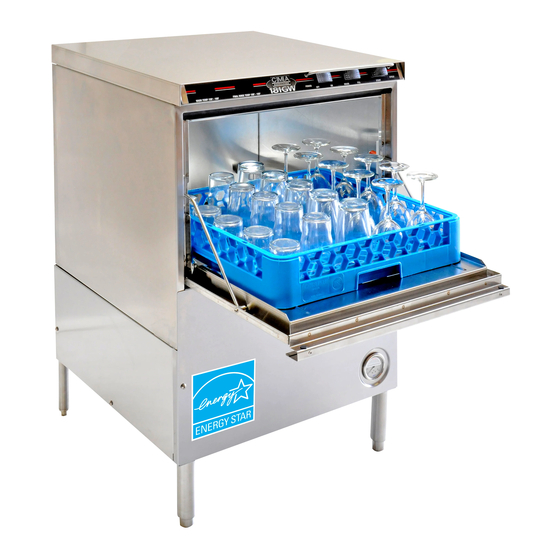
- Page 1 Owner’s Manual Keep with machine for reference MODEL CMA-181GW & INSTALLATION OPERATION Rev 1.00 C M A G L A S S W A S H E R S 1 2 7 0 0 K N O T T A V E N U E...
-
Page 2: Table Of Contents
ABLE OF ONTENTS CMA-181GW ODEL 1. SPECIFICATIONS ..................2 1.1. CMA-181GW ........................2 1.2. CMA-181GW O ..................3 PERATIONAL YCLE 2. GETTING STARTED ..................5 2.1. CMA-181GW ..................5 NTRODUCTION TO 2.2....................6 ECEIVING AND NSTALLATION 2.2.1. Electrical ........................6 2.2.2. -
Page 3: Mcma-181Gw
THIS SYSTEM REQUIRES THREE POWER WIRES, WHICH INCLUDES A CURRENT CARRYING NEUTRAL. AN ADDITIONAL FOURTH WIRE MUST BE PROVIDED FOR MACHINE GROUND. SHIPPING WEIGHT 234# (106 kg) * For machines having "SAFETY TEMP" feature. ** For faster heat recovery. MODEL CMA-181GW INSTALLATION & OPERATION MANUAL Rev. 1.00 Page... -
Page 4: Cma-181Gw Operational Cycle
1.2. CMA-181GW Operational Cycle The CMA-181GW Operational Cycle has a total cycle time of 2 minutes (120 seconds). The Timing Diagram and the steps listed below detail the individual functions that are executed during each Operational Cycle. Seconds: Instant Start Relay... - Page 5 180 degrees. Machine will remain in wash cycle mode until 180-degree rinse temperature is reached, and at this time the cam timer will advance automatically into the rinse cycle and dispense 180 degrees rinse water over the dishes. MODEL CMA-181GW INSTALLATION & OPERATION MANUAL Rev. 1.00 Page...
-
Page 6: Getting Started
180°F final rinse water each cycle. The supply water to the CMA-181GW must be a minimum of 140°F at 24 PSI (Pounds per Square Inch) with a 6 GPM (Gallons Per Minute) flow rate and 60 GPH (Gallons Per Hour) recovery rate. -
Page 7: Receiving And Installation
½”. The supply water to the CMA-181GW must be a minimum of 140°F at 24 PSI (Pounds per Square Inch) with a 6 GPM (Gallons Per Minute) flow rate and 60 GPH (Gallons Per Hour) recovery rate. -
Page 8: Beta Detergent And Rinse Dispenser
1) Remove the 4cam timer assembly (note wire colors and wire placement for all 4cam timer micro switches ) and install 5cam timer in its place. 2) Place all wires removed from 4cam timer assembly in exact position on 5cam timer assembly. MODEL CMA-181GW INSTALLATION & OPERATION MANUAL Rev. 1.00 Page... - Page 9 #21/NC on contactor, and spade end to top terminal on 5 micro switch. HEATER CONTACTOR SafeTtemp harness Dishmachine harness Female bullet connector Male bullet connector Female bullet connector Male bullet connector MODEL CMA-181GW INSTALLATION & OPERATION MANUAL Rev. 1.00 Page...
-
Page 10: Booster Heater Setup
Machine has been “hard-wired” with correctly sized wire Booster tank has been filled with water (before High Limit Switch is reset) High Limit Switch for heater has been reset (after Booster Tank has been filled) MODEL CMA-181GW INSTALLATION & OPERATION MANUAL Rev. 1.00 Page... -
Page 11: Operation
“DRAIN”. Clean the wash tank screen and scrap tray screen. Remove and clean the spray arms. (See wall chart instructions). Rinse cycle temperature must be observed during a rinse cycle while the machine is in operation.. MODEL CMA-181GW INSTALLATION & OPERATION MANUAL Rev. 1.00 Page... -
Page 12: Operating And Cleaning Instructions
Operation 3.3. Operating and Cleaning Instructions MODEL CMA-181GW INSTALLATION & OPERATION MANUAL Rev. 1.00 Page... -
Page 13: Preventive Maintenance Chart
Operation 3.4. Preventive Maintenance Chart MODEL CMA-181GW INSTALLATION & OPERATION MANUAL Rev. 1.00 Page... -
Page 14: Quick Service Guide
Clean bearing and arm jets Tank discharge screen dirty Clean screen Wash tank will not drain. Drain valve not operating Check power to drain valve Drain valve faulty Replace Drain valve MODEL CMA-181GW INSTALLATION & OPERATION MANUAL Rev. 1.00 Page... -
Page 15: Troubleshooting
Heater (never turns off) Defective thermostat Replace thermostat Defective heater contactor Replace heater contactor *The timer assembly motor or micro switches can be replaced independently if that’s the only component that’s failed. MODEL CMA-181GW INSTALLATION & OPERATION MANUAL Rev. 1.00 Page... - Page 16 Defective timer assembly Replace timer assembly* *The timer assembly motor or micro switches can be replaced independently if that’s the only component that’s failed. MODEL CMA-181GW INSTALLATION & OPERATION MANUAL Rev. 1.00 Page...
- Page 17 Defective digital thermometer Replace digital thermometer displays wrong temperature Defective thermister Replace thermister *The timer assembly motor or micro switches can be replaced independently if that’s the only component that’s failed. MODEL CMA-181GW INSTALLATION & OPERATION MANUAL Rev. 1.00 Page...
-
Page 18: Parts Kit
Pump Seal Kit 13417.89 Heater Thermostat 17523.60 High Limit Switch 200°F 00411.00 Microswitch 03202.66 Thermocouple (Control Products) 03604.30 Dema Valve Repair Kit 3/8",1/2" & 3/4 41015.60 Water Solenoid Coil Only 110V MODEL CMA-181GW INSTALLATION & OPERATION MANUAL Rev. 1.00 Page... -
Page 19: Customer Notice
Automatic Dispensing Equipment 1. Applications utilizing automated dispensers for administering warewash chemicals must use 110v dispenser equipment. There is a 110v power block for installing this equipment inside the control panel. MODEL CMA-181GW INSTALLATION & OPERATION MANUAL Rev. 1.00 Page... -
Page 20: Electrical Diagram
Electrical Diagram 6. Electrical Diagram 181GW MODEL CMA-181GW INSTALLATION & OPERATION MANUAL Rev. 1.00 Page... - Page 21 Electrical Diagram 181GW MODEL CMA-181GW INSTALLATION & OPERATION MANUAL Rev. 1.00 Page...
Need help?
Do you have a question about the CMA-181GW and is the answer not in the manual?
Questions and answers