Table of Contents

Subscribe to Our Youtube Channel
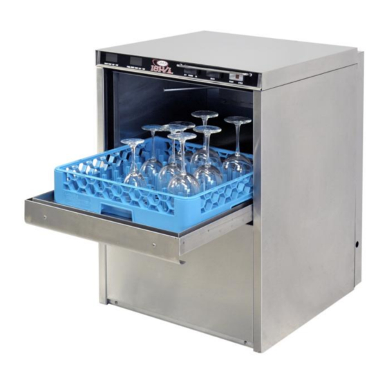
Summary of Contents for CMA Dishmachines CMA-181VL
- Page 1 Owner’s Manual MODEL CMA-181VL & INSTALLATION OPERATION Rev 1.00 C M A D I S H M A C H I N E S 1 2 7 0 0 K N O T T S T R E E T...
-
Page 2: Table Of Contents
ABLE OF ONTENTS CMA-181VL ODEL 1. SPECIFICATIONS ..................2 1.1. CMA-181VL ......................... 2 1.2. CMA-181VL O ..................3 PERATIONAL YCLE 2. GETTING STARTED ..................5 2.1. CMA-181VL ................... 5 NTRODUCTION TO 2.1.1. Plumbing Chart ......................6 2.2....................7 ECEIVING AND NSTALLATION 2.2.1. -
Page 3: Mcma-181Vl
65 PSIG, a pressure regulating valve must be installed in the water line to the dishmachine (by a qualified person). If flow pressure is lower than 30 PSIG, improper operation may result. Page MODEL CMA-181VL INSTALLATION & OPERATION MANUAL Rev. 1.00... -
Page 4: Cma-181Vl Operational Cycle
1.2. CMA-181VL Operational Cycle The CMA-181VL Operational Cycle (including water vapor evacuation) has a total cycle time of three (3) minutes (180 seconds). The Timing Diagram and the steps listed below detail the individual functions that are executed during each Operational Cycle. - Page 5 180 degrees. The Dishmachine will remain in wash cycle mode until a minimum 180-degree rinse temperature is reached, at which time the Cam Timer will advance automatically into the rinse cycle and dispense 180 degree rinse water over the glasses. Page MODEL CMA-181VL INSTALLATION & OPERATION MANUAL Rev. 1.00...
-
Page 6: Getting Started
180°F final rinse water each cycle. The cold water supply to the CMA-181VL must be between 41°F - 65°F at a minimum 30 PSI. (Pounds per Square Inch) with a 6 GPM (Gallons per Minute) flow rate and 60 GPH (Gallons per Hour) recovery rate. -
Page 7: Plumbing Chart
65 seconds. This allows additional condensation removal. Opening the door anytime after the operating cycle is finished and before the fan has timed out, will stop the fan and allow the start of a new cycle. Page MODEL CMA-181VL INSTALLATION & OPERATION MANUAL Rev. 1.00... -
Page 8: Receiving And Installation
A single-phase 230 volt, 60 Hz dedicated circuit should be used to supply electrical energy to the CMA-181VL glass washer (see specification sheet page 2). This system requires three power wires, which include a current carrying neutral. An additional fourth wire must be provided for ground. -
Page 9: Detergent And Rinse Dispenser
180 degree rinse temperature is met, and at this time the cam timer will advance automatically into the rinse cycle and dispense 180 degrees rinse water over the glasses. Page MODEL CMA-181VL INSTALLATION & OPERATION MANUAL Rev. 1.00... -
Page 10: Booster Heater Setup
Drain hose is installed with air gap (discharge 1” above drain) Glasswasher is properly grounded Glasswasher is properly leveled Circuit breaker is labeled “GLASSWASHER” Glass washer has been “hard-wired” with correctly sized wire Page MODEL CMA-181VL INSTALLATION & OPERATION MANUAL Rev. 1.00... -
Page 11: Operation
“DRAIN”. Clean the wash tank screen and scrap tray screen. Remove and clean the spray arms. (See wall chart instructions). Rinse cycle temperature must be observed during a rinse cycle while the unit is in operation.. Page MODEL CMA-181VL INSTALLATION & OPERATION MANUAL Rev. 1.00... -
Page 12: Operating And Cleaning Instructions
Operation 3.3. Operating and Cleaning Instructions Page MODEL CMA-181VL INSTALLATION & OPERATION MANUAL Rev. 1.00... -
Page 13: Preventive Maintenance Chart
Operation 3.4. Preventive Maintenance Chart Page MODEL CMA-181VL INSTALLATION & OPERATION MANUAL Rev. 1.00... -
Page 14: Quick Service Guide
Tank discharge screen dirty Clean screen Wash tank will not drain Drain valve not operating Check power to drain valve Drain valve faulty Replace drain valve Drain pump faulty Replace drain pump Page MODEL CMA-181VL INSTALLATION & OPERATION MANUAL Rev. 1.00... -
Page 15: Troubleshooting
Add water to booster tank to tank activate air pressure switches Heater (never turns off) Defective thermostat Replace thermostat Defective heater contactor Replace heater contactor *The timer assembly motor or micro switches can be replaced independently. Page MODEL CMA-181VL INSTALLATION & OPERATION MANUAL Rev. 1.00... - Page 16 Power light does not light Defective power light Replace power light (red) but machine runs Wash tank or final rinse Defective temperature display Replace temperature display temperature does not display Page MODEL CMA-181VL INSTALLATION & OPERATION MANUAL Rev. 1.00...
- Page 17 Wash tank or final rinse Defective temperature display Replace temperature display displays wrong temperature Defective thermistor Replace thermistor *The timer assembly motor or micro switches can be replaced independently. Page MODEL CMA-181VL INSTALLATION & OPERATION MANUAL Rev. 1.00...
-
Page 18: Parts Kit
L1X/L1-C Drain Valve 120V 00206.70 Pump Seal Kit 13417.89 Heater Thermostat 17523.60 High Limit Switch 200°F 00411.00 Microswitch 03203.01 Dual Temperature Display Kit 00738.15 Solenoid Coil JE 115V/60Hz 00404.82 Motor Mini Contactor Page MODEL CMA-181VL INSTALLATION & OPERATION MANUAL Rev. 1.00... -
Page 19: Customer Notice
Neutral and Ground) extending out of the conduit are provided for easily connecting the power at installation. CMA recommends a minimum 50- amp dedicated circuit, but you should consult your local building code requirements for proper breaker size. Page MODEL CMA-181VL INSTALLATION & OPERATION MANUAL Rev. 1.00... -
Page 20: Electrical Diagram
Electrical Diagram 6. Electrical Diagram 6.1. Control Panel Page MODEL CMA-181VL INSTALLATION & OPERATION MANUAL Rev. 1.00... -
Page 21: Electrical Tray
Electrical Diagram 6.2. Electrical Tray Page MODEL CMA-181VL INSTALLATION & OPERATION MANUAL Rev. 1.00...


Need help?
Do you have a question about the CMA-181VL and is the answer not in the manual?
Questions and answers