Table of Contents
Advertisement
Quick Links
Advertisement
Table of Contents
Troubleshooting

Related Manuals for Gateway Server E-9520T


Summary of Contents for Gateway Server E-9520T
- Page 1 USER GUIDE Gateway® E-9520T Server...
-
Page 3: Table Of Contents
Contents Chapter 1: Checking Out Your Gateway Server ....... .1 Front . - Page 4 Telephone support ........... . .66 Before calling Gateway Customer Care .......66 Telephone support .
- Page 5 Appendix A: Server Specifications ......... . 87 System specifications .
- Page 6 Contents www.gateway.com...
-
Page 7: Chapter 1: Checking Out Your Gateway Server
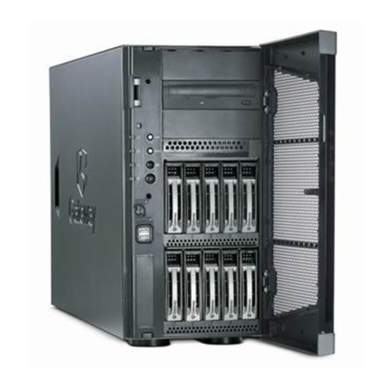
CHAPTER 1 Checking Out Your Gateway Server • Front • Back • Interior • System board • Hot-swap backplanes • Getting Help... -
Page 8: Front
CHAPTER 1: Checking Out Your Gateway Server Front Optical drive SMIL connector Second optical drive (optional) NMI button System fault LED Reset button NIC status LED ID button ID LED Hard drive cages Power LED Power button Case cover lock... -
Page 9: Back
Back Connectors and LEDs PS/2 mouse port PS/2 keyboard port Dual USB ports Serial port VGA port ID LED Dual NIC connectors (RJ-45) Management port (RJ-45) Back AC power connector Power supply status LED Power supply module Case cover thumbscrew... -
Page 10: Interior
CHAPTER 1: Checking Out Your Gateway Server Interior Important Server components with green handles or retention locks can be hot swapped while the server is on. Server components with blue handles or retention locks can only be removed when the server is turned off. -
Page 11: System Board
System board Connectors Feature PCI-X 64-bit/66 MHz expansion slot (J45) PCI-X 64-bit/66 MHz expansion slot (J43) PCI 32-bit/33 MHz expansion Slot (J41) PCI-E x8 expansion slot with x4 speed (J39) PCI-E x8 expansion slot with x4 speed (J37) PCI-E x16 expansion slot with x8 speed... - Page 12 CHAPTER 1: Checking Out Your Gateway Server Feature Management port (RJ-45) (J30) Dual NIC connector (RJ-45) (J28) ID LED (CR13) D-sub VGA port (J24) Serial port (J15) Dual USB connector (J12) PS/2 keyboard and mouse ports (J10) System fan connector (J4)
-
Page 13: Hot-Swap Backplanes
Hot-swap backplanes SAS/SATA backplane Feature SAS/SATA hard drive connector 0 SAS/SATA hard drive connector 1 SAS/SATA hard drive connector 2 SAS/SATA hard drive connector 3 SAS/SATA hard drive connector 4 Hot-swap backplanes Feature C and system ID connector C and system ID connector... -
Page 14: Led Information
CHAPTER 1: Checking Out Your Gateway Server LED information LED Name System Fault Hard drive tray LAN (front) NIC status LEDs Power LED Power supply status LED See the following table for a description of this server’s LEDs and the... -
Page 15: Getting Help
Use the Server Companion DVD to access file utilities, Windows Server 2003 drivers, and documentation for your server and its components. For instructions, see Using Your Server Companion DVD. Gateway provides a variety of information on its Web site to help you use your server. Visit the Gateway Web site at support.gateway.com... - Page 16 CHAPTER 1: Checking Out Your Gateway Server www.gateway.com...
-
Page 17: Chapter 2: Setting Up Your Server
CHAPTER 2 Setting Up Your Server • Setting up the hardware • Protecting from power source problems • Starting your server • Setting up the operating system • Initial hardware settings... -
Page 18: Setting Up The Hardware
Line noise can also be a problem if your server is located near, or shares a circuit with, a device that causes electromagnetic interference, such as a television or a motor. Some surge protectors and uninterruptible power supplies include simple line-conditioning capabilities. www.gateway.com... -
Page 19: Removing And Installing The Bezel
You cannot run your server for an extended period of time while using only the UPS. To buy a UPS, visit accessories.gateway.com. To remove and install the bezel:... - Page 20 Swing the left side of the bezel in to the chassis until the three tabs on the left side of the bezel snap into place. Close the server case by following the instructions in case” on page www.gateway.com “Closing the server...
-
Page 21: Starting Your Server
Starting your server Caution When you connect peripheral devices to the server, make sure that your server and devices are turned off and the power cords are unplugged. Before you start your server for the first time: Make sure that the server and monitor are plugged into a power outlet ■... -
Page 22: Understanding The Power-On Self-Test
You may also need to adjust the monitor’s brightness and contrast controls. If you cannot find the cause of the power loss, contact Gateway ■ Customer Care. For more information, see... -
Page 23: Setting Up The Operating System
Initial hardware settings If you ordered your server with the operating system already installed by Gateway, in most cases it is completely installed and the basic settings are already configured. The Windows Small Business Server operating system may require additional installation, depending on the version you ordered. See your operating system’s documentation for instructions on completing the... - Page 24 CHAPTER 2: Setting Up Your Server www.gateway.com...
-
Page 25: Chapter 3: Maintaining Your Server
CHAPTER 3 Maintaining Your Server • Caring for your server • Preparing for system recovery • System administration • Identifying your server • Updating the baseboard management controller firmware • Using your Server Companion DVD... -
Page 26: Caring For Your Server
Keep the cooling vents free of dust. With your server turned off and ■ unplugged, brush the dust away from the vents with a damp cloth, but be careful not to drip any water into the vents. www.gateway.com... -
Page 27: Preparing For System Recovery
To record your BIOS configuration: Print the appendix for “BIOS Settings” on page Restart your server, then press F2 when the Gateway logo screen appears during startup. The BIOS Setup utility opens. Record the BIOS settings on your printout. Preparing for system recovery... -
Page 28: System Administration
Gateway System Manager (GSM) lets you manage multiple computers on a Windows network from a single window, then implement commands and policies across the network with a single action. With Gateway System Manager, you can run system management tasks which are triggered by certain events or conditions. -
Page 29: Identifying Your Server
Fault resilient booting (the extent depends on the option selected) ■ You should update the BMC firmware when Gateway Customer Care has instructed you to update it. To update the BMC firmware: Download the BMC update file from support.gateway.com and copy onto a USB Disk-on-key device. -
Page 30: Using Your Server Companion Dvd
4.0 and above. To view documents: Insert the Server Companion DVD into the DVD drive on a computer running the Windows operating system. The Gateway Application and Driver Recovery window opens. - OR - If the window does not open, run the file Runmenu.exe on the DVD. -
Page 31: Installing Drivers And Programs
Companion DVD, then open the appropriate subfolder. To update the BIOS and firmware: Download the BIOS update file and firmware from support.gateway.com and copy onto a USB Disk-on-key device. Turn off and boot the system from the SCDVD, then open the command line. -
Page 32: Booting The Server Companion Dvd
With your server turned on, insert the Server Companion DVD into the DVD drive. Restart your server. A message appears asking you to select an option. Press any key to boot from the DVD. The Gateway Options Main Menu appears. Follow any on-screen instructions. -
Page 33: Chapter 4: Installing Components
CHAPTER 4 Installing Components • Preparing to install components • Preventing static electricity discharge • Opening the server case • Closing the server case • Installing and removing drives • Installing memory • Installing and removing PCI expansion cards • Replacing system fans •... -
Page 34: Preparing To Install Components
Is near a grounded outlet so you can test your server after installation. ■ Is near a telephone (in case you need help from Gateway Customer Care). ■ The telephone must be directly connected to a telephone jack and cannot be connected to your server. -
Page 35: Opening The Server Case
Caution ESD can permanently damage electrostatic discharge-sensitive components in the server. Prevent ESD damage by following ESD guidelines every time you open the server case. Opening the server case Caution For correct cooling and air flow, always reinstall the cover before you turn on the server. -
Page 36: Closing The Server Case
Place the cover on the side of the case, then slide it forward until it snaps into place. Tighten the two thumbscrews to hold the cover in place. Lock the case cover lock on the front panel of the case, then close the bezel. Reconnect the power cords and all other cables. www.gateway.com... -
Page 37: Installing And Removing Drives
Installing and removing drives Removing and installing an optical drive Caution The optical drive is not hot-swappable. Before installing or removing the drive, make sure that power is turned off and the power cord(s) is unplugged. Important The hard drive carriers shown in these illustrations may look different than the actual hard drive carriers in your server. - Page 38 (1) marked “PUSH” and pull the optical drive (2) out of the chassis. Remove the four screws (3) from the sides of the optical drive. Install the four screws (1) you removed in the previous step on the sides of the new optical drive. www.gateway.com...
-
Page 39: Removing And Installing A Hard Drive
1-inch high, 3.5-inch hot-swap SATA and SATA II hard drives or ten 1-inch high, 3.5-inch hot-swap SAS hard drives. You can purchase additional drives through your Gateway Sales or Customer Care representative. Channel 0 hot-swap... - Page 40 If you are adding a hard drive, remove the four screws that secure the dummy hard drive to the drive tray, then remove the dummy hard drive from the tray. Using the four screws you removed, install the new hard drive into the drive tray. Screw Screw www.gateway.com Screw Screw...
-
Page 41: Filling Empty Drive Bays
Filling empty drive bays Installing the optional diskette drive Caution The diskette drive is not hot-swappable. Before installing or removing the drive, make sure that power is turned off and the power cord(s) is unplugged. Make sure that the tray’s release lever is open, then slide the new drive fully into the empty hot-swap drive bay and push the lever back into place. - Page 42 (3) included in the optional diskette drive kit. Align the diskette drive with the two clips on the side of the diskette drive carrier (4), then press the diskette drive (5) down firmly until it snaps into place. www.gateway.com...
- Page 43 Secure the diskette drive into the carrier with the two screws (6) included in the optional diskette drive installation kit. Push the diskette drive assembly into the drive bay until it snaps into place. Connect the data and power cables to the back of the diskette drive.
-
Page 44: Installing Memory
DIMM banks must be populated using the following guidelines: DIMM Installation Options - Non-redundant Mode DIMM3 DIMM4 DIMM5 512 MB 1 GB 2 GB 4 GB www.gateway.com “Using the BIOS Setup Utility” on Memory slots DIMM6 DIMM7 DIMM8 Total Usable Memory... - Page 45 DIMM DIMM1 DIMM2 512 MB 512 MB 1 GB 1 GB 2 GB 2 GB 4 GB 4 GB 512 MB 1 GB 2 GB 4 GB 512 MB 512 MB 1 GB 1 GB 2 GB 2 GB...
- Page 46 Align the notch on the new module with the notch in the memory module slot, then press the module firmly into the slot. The tabs on the sides of the memory slot should secure the memory module automatically. www.gateway.com DIMM6 DIMM7...
-
Page 47: Installing And Removing Pci Expansion Cards
Installing and removing PCI expansion cards Removing and installing a PCI card Caution PCI expansion cards are not hot-swappable. Before installing or removing a PCI card, make sure that power is turned off and the power cords are unplugged. - Page 48 From the back of the server, push the expansion card latch in to the locked position. If you opened the card guide initially, rotate the card guide tab down to the locked position. Follow the instructions in “Closing the server case” on page See the card’s documentation for software installation instructions. www.gateway.com...
-
Page 49: Replacing System Fans
Replacing system fans Important The hard drive carriers shown in these illustrations may look different than the actual hard drive carriers in your server. Important The system fans are hot-swappable and can be replaced without turning off your server. -
Page 50: Replacing The Fan Cage And Fan Board
Loosen the two screws (2) on the sides of the fan cage, then lift the fan cage (3) out of the chassis. Remove the cables from the fan board. Loosen the thumbscrew (4) holding the fan board in the chassis. www.gateway.com “To replace a... - Page 51 Slide the fan board away from the power supply (5), then remove it from the chassis (6). Place the new fan board on the standoffs in the chassis, then slide it toward the power supply to lock it down.
-
Page 52: Replacing Or Adding A Processor
Push down, then pull out and up on the two heatsink retention levers (1) and move them out of the way (2). Remove the heatsink (3) from the processor. www.gateway.com “Preventing static electricity discharge” on “Opening the server case” on page... - Page 53 Caution The processor only fits the socket when oriented as indicated. Do not force the processor into the socket to avoid bending the pins or damaging the processor. If the processor does not fit completely, check its orientation and check for bent pins.
-
Page 54: Replacing A Power Supply Module And Power Board
Press down on the retaining clip (1) on the power supply to release the power supply module (2) from the chassis. Pull the power supply module straight out of the server with the handle. It may take considerable force to remove. www.gateway.com “Closing the server case” on page... -
Page 55: Adding An Additional Power Supply Module
Adding an additional power supply module Important The dummy power supply can be removed and the additional power supply installed with the server turned Caution If you remove either of the power supplies for any reason, you must install a dummy power supply to ensure proper airflow and cooling. - Page 56 Reinstall the power supply modules by following the instructions in “Replacing a power supply module and power board” on page Follow the instructions in “Closing the server case” on page www.gateway.com C power, and “System board” on page 5 for the location of “System board”...
-
Page 57: Replacing The Hot-Swap Backplanes
Replacing the hot-swap backplanes Caution The hot-swap backplane is not hot-swappable. Before removing or replacing the backplane, you must first turn off the server and all peripheral devices attached to the server, and remove the AC power cord(s) from the power supply or wall outlet. - Page 58 “Removing and installing a hard drive” on page Replace the bezel by snapping it into place on the front of the server. www.gateway.com “Replacing system Step 4. For...
-
Page 59: Installing And Removing A Mezzanine Board
Installing and removing a mezzanine board This server has two types of optional mezzanine boards. They include a 2-channel SAS mezzanine board and a 2-channel SAS mezzanine board with RAID and battery backup. To install an optional mezzanine board:... - Page 60 Push aside the plastic retaining tabs (1) and pull the mezzanine board (2) straight up and out of the mezzanine board slot. Return the chassis to its upright position, if necessary. Follow the instructions in “Closing the server case” on page www.gateway.com...
-
Page 61: Replacing The Cmos Battery
Return the chassis to its upright position, if necessary. Follow the instructions in Turn on your server, then press F2 when the Gateway logo screen appears during startup. The BIOS Setup utility opens. Restore any BIOS settings that you wrote down in Save all your settings and close the BIOS Setup utility. -
Page 62: Replacing The System Board
Disconnect all cables from the system board, noting their locations and orientation. (You will reconnect the cables after you install the new board.) Loosen the two thumbscrews (2) that secure the system board to the server. www.gateway.com “Preventing static electricity discharge” on “Opening the server case” on page “Installing... - Page 63 Close the server case by following the instructions in case” on page Turn on your server, then press F2 when the Gateway logo screen appears during startup. The BIOS Setup utility opens. Check BIOS settings to make sure that they detect the server’s new hardware, then save your changes (if any) and close the BIOS Setup utility.
- Page 64 CHAPTER 4: Installing Components www.gateway.com...
-
Page 65: Chapter 5: Using The Bios Setup Utility
CHAPTER 5 Using the BIOS Setup Utility • Opening the BIOS Setup utility • Updating the BIOS • Resetting the BIOS... -
Page 66: Opening The Bios Setup Utility
These settings are stored and saved even when the power is off. To open the BIOS Setup utility: Restart your server, then press F2 when the Gateway logo screen appears during startup. The BIOS Setup utility opens. When you select menu items, the Item Specific Help box on the right side of the screen displays specific information about the selection. -
Page 67: Recovering The Bios
To update the BIOS under WinPE: Print the appendix for “BIOS Settings” on page Restart your server, then press F2 when the Gateway logo screen appears during startup. Record any custom BIOS settings on your printout. Download the BIOS update files from support.gateway.com. - Page 68 “Opening the server case” on page Remove the jumper from pins 1-2. Follow the instructions in “Closing the server case” on page Plug in the AC power cords and turn on the server, then verify that the recovery was successful. www.gateway.com...
-
Page 69: Resetting The Bios
To reset the BIOS using the power and reset buttons: Print the appendix for “BIOS Settings” on page 97 Restart your server, then press F2 when the Gateway logo screen appears during startup. The BIOS Setup utility opens. Record any custom BIOS settings on your printout. -
Page 70: Resetting Bios Passwords
Follow the instructions in Remove the jumper from pins 1-2. Follow the instructions in www.gateway.com “Closing the server case” on page “Preventing static electricity discharge” on “Opening the server case” on page “Closing the server case” on page “Opening the server case”... -
Page 71: Chapter 6: Troubleshooting
CHAPTER 6 Troubleshooting • Telephone support • Tutoring and training • Safety guidelines • Error messages • Understanding sensors and sensor readings • Troubleshooting... -
Page 72: Telephone Support
■ have installed it following the instructions provided with it. If you did not purchase the hardware or software from Gateway, see the manufacturer’s documentation and technical support resources. If you have “how to” questions about using a program, see: ■... -
Page 73: Telephone Support
Tutoring and training Resource Gateway Learning Libraries Gateway offers a wide range of customer service, technical support, and information services. Telephone numbers You can access the following services through your telephone to get answers to your questions: Service description Get tutorial assistance for software issues. -
Page 74: Safety Guidelines
This may indicate a defective memory module. Boot messages Boot Failure ... This is a generic message indicating the BIOS could not boot from a particular device. This message is usually followed by other information concerning the device. www.gateway.com... - Page 75 Error messages Invalid Boot Diskette A diskette was found in the drive, but it is not configured as a bootable diskette. Drive Not Ready The BIOS was unable to access the drive because it indicated it was not ready for data transfer.
- Page 76 Error initializing secondary DMA controller. This is a fatal error, often indicates a problem with system hardware. DMA Controller Error POST error while trying to initialize the DMA controller. This is a fatal error, often indication a problem with system hardware. www.gateway.com...
- Page 77 Error messages Checking NVRAM..Update Failed BIOS could not write to the NVRAM block. This message appears when the FLASH part is write-protected or if there is no FLASH part (System uses a PROM or EPROM). Microcode Error BIOS could not find or load the CPU Microcode Update to the CPU. This message only applies to Intel CPUs.
-
Page 78: Understanding Sensors And Sensor Readings
The status and current reading information is for example only. Sensor type Sensor name Sys. ACPI Pwr State ACPI State Module/Board System Reset SYS FAN 1 www.gateway.com Sensor status Current reading Normal State Deasserted Normal operating range 2362.39 RPM... - Page 79 Sensor type Sensor name SYS FAN 2 Voltage System 12V Voltage System 5V Voltage System 5V STBY Voltage System 3.3V Voltage VTT CPU Voltage VCORE 0 Voltage VCORE 1 Voltage VTT MEM Voltage 1.5V NB Voltage 1.9V PHY Voltage 1.8V...
-
Page 80: Troubleshooting
If an error message appears on the screen, write down the exact message ■ before calling Gateway Customer Care. For instructions, see support” on page Restart your server, then open the BIOS Setup utility by pressing and ■... -
Page 81: Beep Codes
Beep codes Beeps Whenever a recoverable error occurs during the power-on self-test (POST), the BIOS displays an error message that describes the problem. The BIOS also sounds a beep code (one long tone followed by two short tones) during POST if the video configuration fails (a faulty video controller) or if an expansion card is not functioning correctly. -
Page 82: Led Information
Identify NIC Front panel status Identify NIC Front panel and states back I/O panel RJ-45 connectors www.gateway.com Troubleshooting steps Same as for 4 beeps. Same as for 4 beeps. Same as for 4 beeps. Color Description Yellow On - Server identification... -
Page 83: Diagnostic Leds
LED Name Power LED Power supply status LED Diagnostic LEDs Function Location Identify the Front panel power state of the system Identify power Power supply supply fault module The BIOS sends a 1-byte hex code to port 80 prior to each POST task. These codes are displayed on eight orange LEDs, located on the system board and available at the back of the server chassis. - Page 84 Programming the memory hole or any kind of implementation that needs an adjustment in system RAM size, if needed. Updates CMOS memory size from memory found in memory test. Allocates memory for Extended BIOS Data Area from base memory. www.gateway.com for more information. “DIM code checkpoints” on...
- Page 85 Check Description point Initialize NUM-LOCK status and programs the KBD typematic rate. Initialize Int-13 and prepare for IPL detection. Initialize IPL devices controlled by BIOS and option ROMs. Initialize remaining option ROMs. Generate and write contents of ESCD in NVRam.
- Page 86 Leaves all RAM below 1 MB Read-Write, including E000 and F000 shadow areas, but closing SMRAM. Restore CPUID value back into register. Give control to BIOS POST (ExecutePOSTKernel). See information. www.gateway.com “POST code checkpoints” on page 77 for more...
- Page 87 Bootblock recovery code checkpoints The bootblock recovery code gets control when the BIOS determines that a BIOS recovery needs to occur because the user has forced the update or the BIOS checksum is corrupt. The following table provides the diagnostic LED codes for...
-
Page 88: Bios
10, 20, 30, 40, 50 Waking from sleep state S1, S2, S3, S4, or S5. The settings in the BIOS Setup utility are not retained Replace the CMOS battery. For instructions, see ■ battery” on page www.gateway.com “Replacing the CMOS... -
Page 89: Optical Drive
Optical drive Expansion cards Hard drive Your server does not recognize an optical drive Restart your server, then open the BIOS Setup utility by pressing and ■ holding F2 while your server restarts. Make sure that the IDE controllers are enabled. -
Page 90: Internet
Open your server and make sure that the memory modules are installed ■ correctly. For instructions, see A memory module may be defective. If possible, try another memory ■ module and see if the error repeats. www.gateway.com NTER “Installing memory” on page NTER... -
Page 91: Monitor
Monitor Power Your server is running but there is no picture Adjust the brightness and contrast controls to the center position. ■ Make sure that the monitor is plugged in and turned on. If the monitor is ■ turned on, the power LED should be lit. -
Page 92: Processor
If you have upgraded your server from one processor to two, you may ■ need to reconfigure your operating system so it recognizes the additional processor. For instructions, see your operating system’s documentation. www.gateway.com... -
Page 93: Appendix A: Server Specifications
APPENDIX A Server Specifications • System specifications • System board specifications • Environmental specifications • Electronic specifications • Additional specifications... -
Page 94: System Specifications
One 725 W hot-swap, power supply module (standard) Additional 725 W hot-swap redundant power supply module (optional) Operating Supports Windows Server 2003 and Windows Small Business Server systems 2003 Certifications FCC Class A ■ CISPR22 ■ EN550222 ■ ■ ■ CSA/CUL ■ ■ www.gateway.com... -
Page 95: System Board Specifications
System board specifications Dual LGA 771-pin sockets Processor 667 MHz to 1333 MHz Front Side Bus (FSB) Supports as many as two Intel Xeon DP (Dual Core) CPUs (3.0 GHz or faster) Chipset Intel Blackford MCH (Northbridge) ■ Intel ESB2E (Southbridge) ■... -
Page 96: Environmental Specifications
128 KB 0E0000h to 0FFFFFh 128 KB 0E0000h to 0EFFFFh 2 MB FC000000h to FFFFFFFFh 64 MB www.gateway.com 40 lbs Function DOS region, base system memory Video or SMM memory Expansion card BIOS and buffer area System BIOS Extended system BIOS... -
Page 97: Interrupts
Interrupts Important If you disable an IDE controller to free the interrupt for that controller, you must physically unplug the IDE cable from the system board. Simply disabling the drive by configuring the BIOS option does not make the interrupt available. - Page 98 +3.3 V +3.3 V -12 V Ground DC_ON (soft on/off ) Ground Ground Ground +5 V +5 V +5 V Ground Processor power connector (J5) Signal Name Ground Ground Ground Ground +12 V +12 V +12 V +12 V www.gateway.com...
- Page 99 VGA connector (J24) Signal Name Green Blue No connection +5 V No connection HSYNC (horizontal sync) VSYNC (vertical sync) Mini-SAS connectors (J50) Signal Name Ground SATA_TX1_C_DP SATA_TX1_C_DN Ground SATA_TX2_C_DP SATA_TX2_C_DN Ground SB_SATA_SCLK SB_SATA_SLOAD Ground Ground Ground Electronic specifications...
- Page 100 APPENDIX A: Server Specifications Signal Name Ground SATA_RX1_C_DP SATA_RX1_C_DN Ground SATA_RX2_C_DP SATA_RX2_C_DN Ground Ground SB_SATA_SDO0 SB_SATA_SDO1 Ground Floppy controller connector (J49) Signal Name MSEN 1 www.gateway.com Signal Name LOWDEN_N 2M_MED DSEL3_N INDEX_N MOTON0_N DSEL1_N DSEL0_N MOTON1_N DIR_N STEP_N WDATA_N WRTEN_N...
- Page 101 Signal Name MSEN 0 Serial port connector (J15) Signal Name RXDATA TXDATA Keyboard and Mouse connectors Signal Name Keyboard (or mouse) data +5 V Keyboard (or mouse) clock Electronic specifications Signal Name TRK_0_N WPROTECT_N RDATA_N HDSEL_N DSKCHING_N Description Data Carrier Detect1...
-
Page 102: Additional Specifications
For more information about your server, such as memory size, hard drive size, and processor type, visit Gateway’s eSupport page at support.gateway.com. The eSupport page also has links to additional Gateway documentation and detailed specifications for your own server. www.gateway.com... -
Page 103: Appendix B: Bios Settings
APPENDIX B BIOS Settings... - Page 104 For a complete list of viewable BIOS settings, run the BIOS Setup utility. To view all BIOS settings: Restart your server Press F2 when the Gateway logo screen appears during startup. The BIOS Setup utility opens. Select menus and submenus to display setting information. BIOS submenu CPU Configuration www.gateway.com...
- Page 105 BIOS menu BIOS submenu Setting Hardware Prefetcher Adjacent Cache Line Prefetch Virtualization Technology (VT) Memory Configuration Memory Performance Mode Total Memory Capacity Memory Redundancy DIMM 1 DIMM 2 DIMM 3 DIMM 4 DIMM 5 DIMM 6 DIMM 7 DIMM 8...
- Page 106 SATA Port 0 SATA Port 1 SATA Port 2 SATA Port 3 SATA Port 4 SATA Port 5 Hard Disk Write Protect IDE Detect Time Out (Sec) www.gateway.com Value SATA Only PATA Pri, SATA sec SATA Pri, PATA PATA only RAID ACHI...
- Page 107 BIOS menu BIOS submenu Setting Super I/O Configuration Onboard Floppy Controller Floppy A Serial Port 1 Address Serial Port 1 IRQ Serial Port 2 Address Serial Port 2 IRQ PS/2 Keyboard PS/2 Mouse USB Configuration USB Devices Enabled (List...
- Page 108 GTW MzBoard Option ROM Boot Settings Configuration Quick Boot Quiet Boot Bootup Num-Lock POST Error Pause Boot Device Priority 1st Boot Device nth Boot Device Hard Disk Drives 1st Drive www.gateway.com Value Disabled Enabled Disabled Enabled Disabled Enabled Disabled Enabled Disabled Enabled Disabled...
- Page 109 BIOS menu Security BIOS submenu Setting nth Drive Removable Drive 1st Drive nth Drive CD/DVD Drives 1st Drive nth Drive Administrator Password (Installed/Not installed) User Password (Installed/Not installed) Change Administrator Password (Set or clear Admin password) User Access Level...
- Page 110 Serial Port Number (Base address and IRQ) Serial Port Mode Flow Control Redirection After BIOS POST Terminal Type VT-UTF8 Combo Key Support IPMI Configuration Status of BMC www.gateway.com Value Disabled Enabled COM1 COM2 115200 8,n,1 57600 8,n,1 19200 8,n,1 09600 8,n,1 None...
- Page 111 BIOS menu Exit BIOS submenu BIOS 2nd level Configuration BIOS submenu IOAT Restore on AC Power Loss Wake on RING function Plug & Play BMC detection The following second level submenus are accessed from the submenu indicated in the first column.
- Page 112 DMA Mode S.M.A.R.T. 32Bit Data Transfer Setting submenu USB Mass Storage Device Configuration USB Mass Storage Reset Delay www.gateway.com Value Device LBA mode Device block mode Device PIO mode Device Async DMA mode Device Ultra DMA mode Device S.M.A.R.T. support...
- Page 113 BIOS submenu BIOS 2nd level Setting submenu Device #1 Emulation Type Device #n Emulation Type Value Only displayed if a device is detected. Includes a DeviceID string returned by the USB device. Auto Floppy Forced FDD Hard Disk CDROM Only displayed if a device is detected.
- Page 114 APPENDIX B: BIOS Settings www.gateway.com...
-
Page 115: Appendix C: Safety, Regulatory, And Legal Information
APPENDIX C Safety, Regulatory, and Legal Information... -
Page 116: Important Safety Information
Your Gateway system is designed and tested to meet the latest standards for safety of information technology equipment. However, to ensure safe use of this product, it is important that the safety instructions marked on the product and in the documentation are followed. -
Page 117: Regulatory Compliance Statements
Regulatory compliance statements United States of America Caution Changes or modifications not expressly approved by Gateway could void the FCC compliance and negate your authority to operate the product. Federal Communications Commission (FCC) Unintentional emitter per FCC Part 15... -
Page 118: Fcc Declaration Of Conformity
FCC declaration of conformity Responsible party: Gateway Companies, Inc. 610 Gateway Drive, North Sioux City, SD 57049 (605) 232-2000 Fax: (605) 232-2023 Product: ■ Gateway E-9520T Server For unique identification of the product configuration, please submit the 10-digit serial number found on the product to the responsible party. -
Page 119: Environmental Information
Environmental information All Gateway systems equipped with CD and DVD drives comply with the appropriate safety standards, including IEC 825. The laser devices in these components are classified as “Class 1 Laser Products” under a US Department of Health and Human Services (DHHS) Radiation Performance Standard. - Page 120 Due to continuing system improvements, Gateway is not responsible for inaccurate information which may appear in this manual. For the latest product updates, consult the Gateway Web site at www.gateway.com. In no event will Gateway be liable for direct, indirect, special, exemplary, incidental, or consequential damages resulting from any defect or omission in this manual, even if advised of the possibility of such damages.
-
Page 121: Index
DIM code checkpoints POST code checkpoints DIM code checkpoints DIMM see memory diskette drive connector location display troubleshooting documentation Gateway Web site Server Companion DVD drive bays location drivers installing drives configuring diskette hard drive hot-swap installing optical... - Page 122 Gateway Customer Care Learning Libraries Web address Web site Gateway System Manager hard drive indicator installing LED indicator removing troubleshooting heat sink installing help telephone support tutoring hot-swap...
- Page 123 BIOS configuration tape drive cleaning location technical support Customer Care resources tips before contacting telephone support training Gateway Learning Libraries troubleshooting add-in card battery beep codes BIOS card diagnostic LEDs error messages expansion card general guidelines general safety guidelines...
- Page 124 (UPS) updating the BIOS USB ports internal connector location user password VGA port Web site Gateway www.gateway.com...
- Page 126 A MAN E-9520T USR GDE R0 10/06...
Need help?
Do you have a question about the Server E-9520T and is the answer not in the manual?
Questions and answers