
Related Manuals for GarrettCom Magnum 1016


Summary of Contents for GarrettCom Magnum 1016
- Page 1 Magnum Workgroup Hubs “Ten Series” Models 1008, 1016 and 1024 Installation and User Guide www GarrettCom com...
- Page 2 NEBS is a trademark of Telcordia Technologies UL is a registered trademark of Underwriters Laboratories GarrettCom, Magnum and Personal Switch are trademarks and Personal Hub is a registered trademark of GarrettCom, Inc. Important: The Magnum 1000 series workgroup hub family contains no user serviceable parts.
- Page 3 Magnum 1000 Workgroup Hubs Installation and User Guide (04/02) Contacting GarrettCom, Inc Please use the mailing address, phone and fax numbers and email address listed below: GarrettCom, Inc. 47823 Westinghouse Drive Fremont, CA 94539 Phone (510) 438-9071 Fax (510) 438-9072 Website: http://www.GarrettCom.com...
-
Page 4: Table Of Contents
2.4.7 RPM-TP 2.4.8 BPM-BNC ...16 2.4.9 BPM-AUI ...16 2.4.10 BPM-FST...17 2.4.11 BPM-TP...17 2.4.12 Special Option -- Second Bonus Port (Models 1016 and 1024)...18 2.5 Features and Benefits...19 2.6 Applications... E 3.0 INSTALLATION...22 3.1 Table-Top or Rack-Mount...22 3.2 Powering the Magnum 1000 Workgroup Hubs ...22 3.3 Ethernet Media Connections...23... - Page 5 Rev D 04/02 : Included Power Budget calculation and Rack mounting as well as updated Appendix B with 24VDC & 125VDC option. Rev C 04/01 : Change the company name to GarrettCom, Inc. (Formerly it was Garrett Communications). There are no changes to the content of the...
- Page 6 The Magnum Line ETHERNET CONNECTIVITY PRODUCTS "DESIGNED AND MANUFACTURED IN THE USA" GarrettCom, Inc.offers the premium-quality Magnum line of Ethernet LAN connectivity products with industry-standard functionality and built-in fiber configurability. Magnum products are designed for use in demanding Carrier Class, Industrial Grade and OEM applications where reliability is a primary consideration.
-
Page 7: Specifications
Ambient Relative Humidity: 10% to 95% (non-condensing) Packaging Enclosure: High strength metal. Suitable for wiring closet shelf, Dimensions: 1008: Weight: Cooling method: Convection www GarrettCom com Installation and User Guide (04/02) 10BASE-FL & FOIRL. RJ-45 shielded, female D-sub 15-pin female with slide lock IEC recessed male Storage Temperature: -5°... -
Page 8: Warranty
The RJ-45 connector is shielded; it accepts RJ-45 eight-pin plugs for unshielded and shielded twisted pair wiring. ** Internal termination switch for BNC, no "T" connector is required. *** MDI-X (Media Dependent Interface - Crossover) switch for RJ-45 up-link, Specifications - Bridge Port Modules (BPMs) -
Page 9: Ordering Information
Magnum 1008 Magnum 1016 Magnum 1024 Magnum 10xx-pm Magnum 10xx-48V GarrettCom, Inc. reserves the right to change specifications, performance characteristics and/or model offerings without notice. www GarrettCom com Installation and User Guide (04/02) Eight port 10BASE-T Hub with shielded RJ-45 connectors and front-mounted LEDs. -
Page 10: Introduction
This package should contain: Magnum 1008, 1016 or 1024 Workgroup Hub Set of metal “ears” for optional rack-mounting (Models 1016, 1024 only) AC Power Cord (U.S. and other 115 VAC only) Installation and User Guide Product Registration Card Remove the items from the shipping container. -
Page 11: Magnum 1008 Workgroup Hub
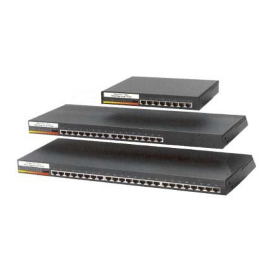
Magnum 1000 Workgroup Hubs The family of Magnum 1000 Workgroup Hubs is comprised of Models 1008 (pronounced “ten oh-eight”), 1016 (“ten sixteen”) and 1024 (“ten twenty-four”). These models are equipped with 8, 16 or 24 front-mounted, shielded RJ-45 ports, respectively. -
Page 12: Magnum 1016 And 1024 Workgroup Hubs
2.2.2 Magnum 1016 and 1024 Workgroup Hubs The Magnum 1016 Workgroup Hub is equipped with 16 front-mounted, shielded RJ-45 ports, 1 rear-mounted basic AUI port and 1 rear Bonus Port slot (see Figure 2.2.2a). The left-most front RJ-45 port (port 1) is equipped with a slide switch to allow cascading or an up-link without a crossover cable. - Page 13 115 - 230 VAC Figure 2.2.2c: Rear view - Magnum 1016 and 1024 Workgroup Hubs The Bonus Port slot of a Magnum 1016 or 1024, shown in Figure 2.2.2c, may be optionally configured with any Magnum Port Module (PM). This option gives the Magnum 1016s and 1024s great flexibility to easily conform to any standard Ethernet media environment.
-
Page 14: Basic Aui Port And Port Module Internal Connections
Workgroup Hubs. (The Model 1024 is shown in the figure, but all rear port connections are identical for the Model 1016). One rear port always has the basic AUI port in it. The bonus port slot, in the center of the chassis rear, is available for configuring any PM. -
Page 15: Bonus Port Configuration Options - Rpms And Bpms
Fiber ST), SMF (Ethernet single-mode Fiber), and RJ-45 (10BASE-T UTP and STP). They are shown in Figure 2.4a. Figure 2.4a: Magnum RPM Cards: RPM-BNC, RPM-AUI, RPM-DTE, RPM-FST, RPM-SMF & RPM-TP. www GarrettCom com Installation and User Guide (04/02) Bonus port for optional PM card (BPM shown) - Page 16 Each Port Module is normally factory installed in Magnum 1000 Hub units. Alternatively, PMs may sometimes be installed in the field by a trained technician. The following is a detailed description of each Port Module. www GarrettCom com Installation and User Guide (04/02) Figure 2.4b:...
-
Page 17: Rpm-Bnc
To take advantage of internal termination, the slide switch should be in the "DOWN" (or right-side) position. In this configuration, the 10BASE2 segment is directly attached to the BNC port where it is internally terminated. When the switch is in the "UP" (or left-side) position, the BNC port requires a "tee"... -
Page 18: Rpm-Dte
AUI drop cables to any device that is equipped with an AUI port. Examples of such devices include servers, routers, bridges, hubs, and UNIX workstations. www GarrettCom com Installation and User Guide (04/02) Standard 15-pin female AUI, with slide-lock... -
Page 19: Rpm-Fst (Fiber St, Twist-Lock Connector)
Its functionality is exactly like the RPM-FST, but it is equipped with an SC-type "snap-in" connector. Please refer back to section 2.4.4 for details. www GarrettCom com Installation and User Guide (04/02) 10BASE-FL, FOIRL ST Connectors LINK 0 - 2 km* 0.5 - 3 km**... -
Page 20: Rpm-Smf (Single Mode Fiber)
5 & 6 for single-mode. The other jumper positions are not used for single-mode fiber. JUMPER ACROSS DISTANCES SUPPORTED 1 - 2 3 - 4 5 - 6 www GarrettCom com Installation and User Guide (04/02) Single-mode ST Connectors LINK not used not used... -
Page 21: Rpm-Tp (Twisted Pair)
1 = receive+, 2 = receive-, 3 = transmit+, 6 = transmit-, other pins not used. When the TP crossover switch is UP, the pins of the RJ-45 port are per the standard for up-links using twisted pair wiring, i.e., the transmit and the receive pairs are exchanged: 1 = transmit+, 2 = transmit-, 3 = receive+, 6 = receive-, other pins not used. -
Page 22: Bpm-Bnc
Magnum unit housing the BPM) from the connecting network (i.e., the users and devices connected through the BPM’s media connector). The BPM-BNC module is designed with a special switch -selectable internal termination function that eliminates the need for a "tee" connector and a 50 ohm terminator. -
Page 23: Bpm-Fst
(UTP) and shielded twisted pair (STP) segment connections. The BPM-TP module is also equipped with a Media Dependent Interface- Crossover (MDI-X) slide switch to allow for cascaded connections. This feature eliminates the need for a special twisted pair crossover cable (see RPM-TP, 2.4.7). -
Page 24: Special Option -- Second Bonus Port (Models 1016 And 1024)
2.4.12 Special Option -- Second Bonus Port (Models 1016 and 1024) In special cases, it may be desirable to configure the Magnum 1016 or 1024 Workgroup Hub with a second Port Module. The 1016 and 1024 Workgroup Hubs were designed to accommodate such a configuration, and the second Bonus Port may be configured by a trained technician and connected into header J1-RPM. -
Page 25: Features And Benefits
An internal universal AC power supply allows any Magnum 1000 Workgroup Hub unit to be used throughout the world. The power cable attaches via a standard recessed IEC-type connector in the rear www GarrettCom com Installation and User Guide (04/02) -
Page 26: 2.6 Applications
(10BASE2) segment. One of the workgroups is comprised of two Magnum 1000’s cascaded by means of the up-link switch of a port 1 (for details on the up-link switch, refer to section 3.3.1, “Connecting Twisted Pair (RJ-45, Unshielded or Shielded). Each workgroup is connected to the ThinNet through a rear-mounted BNC-type RPM. - Page 27 (i.e., is contained inside of each Magnum 1000 Hub segment by the BPMs) and does not consume bandwidth on the rest of the network. Refer to section 4.2, “Magnum 1000 BPM Local Bridge Functionality”, for more information about the operation of the BPMs. www GarrettCom com...
-
Page 28: Table-Top Or Rack-Mount
Installation and User Guide (04/02) Magnum 1008 Workgroup Hub Rack Mount Brackets (Optional) Magnum 1000 Workgroup Hub GARRETT Magnum 1000 Workgroup Hub GARRETT Magnum 1000 Workgroup Hub GARRETT Magnum 1016 and 1024 Workgroup Hubs Rack Mount Brackets (Included) Figure 3.1: Magnum 1000’s,... -
Page 29: Ethernet Media Connections
10BASE-T cables and wiring may be used. Connect the other end of the cable to the corresponding device. When proper connection and power have been established, the port’s LINK LED will illuminate GREEN. www GarrettCom com Installation and User Guide (04/02) AUI (female) DTE (male) -
Page 30: Connecting Thicknet 10Base5 (Aui)
BPM-TP ) are equipped with a cross-over slide switch to accommodate repeater-to-repeater connections without special cross-over connectors. Set the slide switch to the “left” (for port 1) or “down” (for PM-TP) position for normal twisted pair cable segments from the hub port to a user device. Set the slide switch to the “right”... -
Page 31: Connecting Thinnet 10Base2 (Bnc)
The PM-BNC port is specially equipped with an internal termination switch on the front of the card (see Section 4.1 for a description of this switch). This eliminates the need to use a "tee" connector when the BNC cable is ending at the connection to this PM. -
Page 32: Connecting Fiber Optic (Sma-Type, "Screw-On")
The same five-step procedure for multi-mode fiber ST-type applies to single- mode fiber connectors. Follow the five steps listed in Section 3.3.5 above. www GarrettCom com Installation and User Guide (04/02) -
Page 33: Power Budget Calculations For Magnum 1000S
Installation of a Magnum 1000 Series Hub in a 19” rack is a simple procedure. The units are 1U (1.75”) high. When properly installed, the front-mounted LED status indicators should www GarrettCom com Installation and User Guide (04/02) (min) - P (min) Std. -
Page 34: Operation
Magnum 1000 Repeater Functionality Repeater Functionality: Each hub port operates in conjunction with the controller functions of the Magnum 1000 Hub’s base unit, functioning together as a fully compliant Ethernet repeater. www GarrettCom com Installation and User Guide (04/02) Magnum 1000 9 10... - Page 35 Each RJ-45 port is represented by its own LINK LED. LINK should always be on during normal operation. LINK is OFF if connectivity or power is lost anywhere along the segment. www GarrettCom com Installation and User Guide (04/02)
-
Page 36: Magnum 1000 Bpm Local Bridge Functionality
4.2c and 4.2d respectively. When an internal packet’s source address is not already in the address table, it is written www GarrettCom com Installation and User Guide (04/02) Figure 4.2a: Internal Internal packets are filtered when... - Page 37 For example, a segment containing a group of workstations and servers may have heavy local traffic, but only a small amount of traffic that is www GarrettCom com Installation and User Guide (04/02) Figure 4.2d: External Packet Filtered...
-
Page 38: Power Requirements
See Section 1.1, “Technical Specifications: Power Supply (Internal)” for detailed information on the internal power supply units. For optional 48VDC internal power supply information, see Appendix B. www GarrettCom com Installation and User Guide (04/02) Local nodes with heavy local traffic,... -
Page 39: Troubleshooting
Magnum 1000 series workgroup hub is not performing as expected, do not attempt to repair the unit; instead contact your supplier for assistance or contact GarrettCom Customer Support. Before Calling for Assistance If difficulty is encountered when installing or operating the unit, refer back to the Installation Section of the applicable chapter of this manual. -
Page 40: When Calling For Assistance
Return Material Authorization (RMA) Procedure All returns for repair must be accompanied by a Return Material Authorization (RMA) number. To obtain an RMA number, call GarrettCom Customer Service at (510) 438-9071 during business hours in California or email to support@garrettcom.com). When calling, please have the following information readily available: Name and phone number of your contact person. -
Page 41: Shipping And Packaging Information
(see Warranty Information, Appendix A, for complete details). However, if the problem or condition causing the return cannot be duplicated by GarrettCom, the unit will be returned as: GarrettCom reserves the right to charge for the testing of non-defective units under warranty. -
Page 42: Appendix B : Internal Dc Power Supply Option
Disconnecting the power source is used for powering the hub on and off when it is placed into or taken out of service. www GarrettCom com Installation and User Guide (04/02) “, “GND”, “+”... - Page 43 (-), positive (+), and chassis ground (GND). The connection procedure is straightforward. Simply connect the DC leads to the Switch’s power terminals, positive (+) and negative (-) screws. The use of Ground (GND) is optional; it connects to the Switch chassis.
- Page 44 125VDC power supply is identical to that of the standard AC-powered models. B6.0 ORDERING INFORMATION To order the optional -48VDC power supply factory installed, add a suffix of “-48VDC” after the product’s standard model #. Example: Magnum 1016-48VDC. Similarly for “24VDC” : Magnum 1016-24VDC. B7.0 TROUBLESHOOTING Please refer to Section 6.0 for troubleshooting...
Need help?
Do you have a question about the Magnum 1016 and is the answer not in the manual?
Questions and answers