Table of Contents
Advertisement
Quick Links
Advertisement
Table of Contents

Subscribe to Our Youtube Channel
Related Manuals for Zeta NPAD


Summary of Contents for Zeta NPAD
- Page 1 INSTALLATION MANUAL...
-
Page 2: Table Of Contents
PREMIER AD INSTALLATION MANUAL. Software:31/3/04 & LC6 CONTENTS PREMIER AD OVERVIEW……………………………………………………… 1.1 SETTING THE DEVICE ADDRESS (DETECTORS, CALL POINTS & SOUNDERS) LIST OF COMPATIBLE EQUIPMENT………………………………………… 2.1 SUPPORTED SOUNDER TYPES & THEIR APPLICATIONS INTRODUCTION…….…………………………………………………………… THE PCBS USING THIS MANUAL ABOUT THE PREMIER AD FACP & INTEGRAL PSE DESIGNING THE SYSTEM EQUIPMENT GUARANTEE FIRST FIX GUIDELINES…………………………………………………………. -
Page 3: Premier Ad Overview
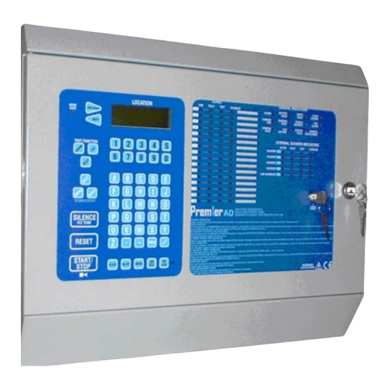
PREMIER AD INSTALLATION MANUAL. Software:31/3/04 & LC6 1.PREMIER AD OVERVIEW The Premier AD is a 2-loop analogue addressable fire alarm control panel designed to EN54 part 2 & 4. It has 2 addressable loops, each capable of having 126 devices, and also 4 independently operating sounder circuits. -
Page 4: List Of Compatible Equipment
PREMIER AD INSTALLATION MANUAL. Software:31/3/04 & LC6 2. LIST OF COMPATIBLE EQUIPMENT Stock No Product Code Device 37-150 PR-AD Premier AD Fire Alarm Panel 37-155 PREP-AD Premier AD Repeater 80-110 FEAI2000 Fyreye Addressable Ionisation Detector 80-120 FEAO2000 Fyreye Addressable Optical Detector 80-130 FEAH2000 Fyreye Addressable Heat Detector... -
Page 5: Introduction
PREMIER AD INSTALLATION MANUAL. Software:31/3/04 & LC6 3.INTRODUCTION THIS FIRE ALARM CONTROL PANEL IS CLASS 1 EQUIPMENT AND MUST BE EARTHED This equipment must be installed and maintained by a qualified and technically experienced person. 3.1 HANDLING THE PCBS If the PCBs are to be removed to ease fitting the enclosure and cables, care must be taken to avoid damage by static. -
Page 6: First Fix Guidelines
PREMIER AD INSTALLATION MANUAL. Software:31/3/04 & LC6 If this equipment is not fitted and commissioned according to our guidelines, and the relevant National Standards, by an approved and competent person or organisation, the warrantee may become void. 4. FIRST FIX All wiring must be installed to meet BS5839: Pt1: 2002 and BS 7671 (Wiring Regs) standards. -
Page 7: Addressable Loop Wiring Diagram
PREMIER AD INSTALLATION MANUAL. Software:31/3/04 & LC6 4.4 ADDRESSABLE LOOP WIRING DIAGRAM The Premier AD comes with two addressable loops. Addressable detectors, addressable call points, addressable loop powered sounders and several other interface units can be connected to these loops. A MAXIMUM OF 126 DEVICES CAN BE CONNECTED TO EACH LOOP. Side A +ve Side A -ve FYREYE ADDRESSABLE... -
Page 8: Specific Device Wiring Instructions
PREMIER AD INSTALLATION MANUAL. Software:31/3/04 & LC6 SPECIFIC DEVICE WIRING INSTRUCTIONS: Fyreye Common Base Fyreye Addressable Detector Relay Base FE-CB FEA-RB 80-050 80-080 LOOP + IN LOOP + OUT LOOP + IN LOOP + OUT RELAY OUTPUT LOOP - IN LOOP - OUT LOOP - IN LOOP - OUT... - Page 9 PREMIER AD INSTALLATION MANUAL. Software:31/3/04 & LC6 Zeta Input Unit Zeta Input Output Unit ZIOU 48-100 48-105 47K EOL 0.5W 47K EOL 0.5W LOOP - IN LOOP - OUT LOOP + IN LOOP + OUT LOOP - OUT LOOP - IN LOOP + IN LOOP + OUT Zeta Sounder Controller Circuit...
-
Page 10: Auxiliary Input Wiring Examples
PREMIER AD INSTALLATION MANUAL. Software:31/3/04 & LC6 4.6 AUXILIARY INPUT WIRING EXAMPLES There is one non-latching auxiliary input connection on the Fire Alarm Panel. Class Change Input (CC): This will energise all alarm outputs continuously when the CC terminals are shorted together. (This includes the 4 conventional sounder outputs & any loop powered sounders.) Typical auxiliary input wiring options AUX FIRE RELAY... -
Page 11: Mounting The Fire Alarm Panel
PREMIER AD INSTALLATION MANUAL. Software:31/3/04 & LC6 5. MOUNTING THE FIRE ALARM PANEL It is recommended that the panels door be removed to avoid accidental damage. Also, the termination PCB could be removed and stored in a safe place, while fixing the back box to the wall. 5.1 PLANNING CABLE ENTRY Fig.2 below shows the location of the cable entries to facilitate planning of wiring (home runs) to be brought to the panel. -
Page 12: Connecting Mains & Battery Power
PREMIER AD INSTALLATION MANUAL. Software:31/3/04 & LC6 6 CONNECTING MAINS & BATTERY POWER 6.1 CONNECTING THE MAINS POWER The panel should be connected to 220-240V AC by a 3A rated spur to the fuse box with 1mm to 2.5mm 3-core INLET MAINS cable. -
Page 13: Field Device Termination
PREMIER AD INSTALLATION MANUAL. Software:31/3/04 & LC6 THERMISTOR Figure 4a:Thermistor location The thermistor is used to prevent overcharging the batteries in high ambient temperatures. 7. FIELD DEVICE TERMINATION 7.1 TERMINATING THE ADDRESSABLE LOOPS AND ALARM (SOUNDER) CIRCUITS. INLET MAINS Brass Glands SUPPLY All cables entering the enclosure should have brass cable glands,... -
Page 14: Designing The System & Configuring The Facp
PREMIER AD INSTALLATION MANUAL. Software:31/3/04 & LC6 8. DESIGNING THE SYSTEM & CONFIGURING THE FACP Configuring the premier AD is a fairly straightforward matter. It just takes a bit of thought to zone allocation during the system design stage. 1. Decide on the zone allocation for the system. Each zone can have a maximum of 16 devices fitted. - Page 15 PREMIER AD INSTALLATION MANUAL. Software:31/3/04 & LC6 Configuration in 6. Select Option 3 (Configure). The panel will say Progress Configuration in progress please wait. This takes around 20 seconds. Please Wait 7. To check that the panel has read all the devices on 00SCC 14Loop 1 loop 1, select option 1 Lp1 Dev.
-
Page 16: Loop Contents Fault Finding
PREMIER AD INSTALLATION MANUAL. Software:31/3/04 & LC6 8.1 LOOP CONTENTS FAULT FINDING If the loop contents are different to what was expected, then there may be some wrong connections to devices (they are polarity sensitive), or double addresses on the loop. (A double address is when 2 or more devices have been set to the same address, so they both answer at the same time.) If a panel detects a Device Type: HEAT *... - Page 17 PREMIER AD INSTALLATION MANUAL. Software:31/3/04 & LC6 ADDRESS SWITCHES ADDRESS SWITCHES ADDRESS SWITCHES ADDRESS SWITCHES 1 2 3 4 5 6 7 1 2 3 4 5 6 7 1 2 3 4 5 6 7 1 2 3 4 5 6 7 n o t u s e d 32 =...
-
Page 18: Zone Disablement
PREMIER AD INSTALLATION MANUAL. Software:31/3/04 & LC6 9. ZONE DISABLEMENT The Premier AD is designed to operate as a zone based panel. You can therefore only disable a whole zone. It is not possible to disable individual devices. 9.1 WHY USE ZONE DISABLEMENT To aid commissioning and assist routine maintenance checks, any of the zones or the sounder circuits can be disabled. -
Page 19: Test Mode
PREMIER AD INSTALLATION MANUAL. Software:31/3/04 & LC6 10. TEST MODE 10.1 WHY USE TEST MODE To aid commissioning and assist routine maintenance check, a non-latching ‘one man test’ facility is available. When a detector or manual call point is triggered on any zone in Test, the Alarm sounders operate for approximately eight seconds on and four seconds off. -
Page 20: General Fault Finding
PREMIER AD INSTALLATION MANUAL. Software:31/3/04 & LC6 11. GENERAL FAULT FINDING 11.1 COMMON FAULT. This is a general indicator which lights whenever a fault is present. It doesn’t refer to a specific fault. 11.2 ZONE FAULTS There are several reasons for the zone fault LED to light. 1. -
Page 21: Earth Faults
PREMIER AD INSTALLATION MANUAL. Software:31/3/04 & LC6 11.4 EARTH FAULTS FAULT An EARTH fault indicates that something is shorting to earth (usually through the cable screen). Disconnect the earth Earth Fault screens one at a time to determine the problem line. (Note: connecting other equipment , eg an oscilloscope , to the panel can give an earth fault) The voltage between battery –Ve and earth should be 14-16 volts. -
Page 22: Loop Wiring Faults
PREMIER AD INSTALLATION MANUAL. Software:31/3/04 & LC6 11.9 LOOP WIRING FAULTS FAULT A loop fault can be caused by a break, or short circuit in the Loop wiring. Open the panel and look for the 4 green LEDs on Loop Fault Exists the termination PCB. -
Page 23: Standby Battery Requirements
Fire Alarm System Product Code Device (mA) (mA) (mA) Loop System PREMIER AD FIRE ALARM CONTROL PANEL NPAD REP-AD PREMIER AD REPEATER PANEL FEAI2000 Fyreye Addressable Ionisation Smoke Detector FEAO2000 Fyreye Addressable Optical Smoke Detector Fyreye Addressable Heat Detector FEAH2000... -
Page 24: Standby Battery Calculation
PREMIER AD INSTALLATION MANUAL. Software:31/3/04 & LC6 12.1 STANDBY BATTERY CALCULATION In order to calculate the standby battery size required, the following formula can be used:- Battery Size (Standby time in Amp Hours) = 1.25 x [(T ) + (T x (I Where: = Maximum time in hours required for the alarm [½... -
Page 25: Pcb Termination Connections
PREMIER AD INSTALLATION MANUAL. Software:31/3/04 & LC6 13. PCB TERMINATION CONNECTIONS. LOOP 1A SND 1 LOOP 1B SND 2 LOOP 2A SND 3 LOOP 2B SND 4 FIRE RELAY FAULT RELAY CLASS CH SERIAL REPAETER AUX SUP NO CM NC NO CM NC CONN19 CONN12 CONN20 CONN13 CONN21 CONN14 CONN22 CONN18 CONN15 CONN16 CONN17 CONN28 CONN24 CONN25 CONN23... -
Page 26: Control Panel Electrical Specifications
PREMIER AD INSTALLATION MANUAL. Software:31/3/04 & LC6 14. PANEL SPECIFICATIONS 14.1 ENCLOSURE SPECIFICATIONS DESCRIPTION VALUE ENCLOSURE SIZE 480 x 395 x 100 mm TOP CABLE ENTRIES 20 x 19mm DIA GROMMETED ENTRIES BOTTOM CABLE ENTRIES 10 x 19mm KNOCKOUT ENTRIES REAR CABLE ENTRIES 2 SNAP OUTS, 60 x 20mm 14.2 ELECTRICAL SPECIFICATIONS...
Need help?
Do you have a question about the NPAD and is the answer not in the manual?
Questions and answers