
Related Manuals for Zeta INFINITY 8


Summary of Contents for Zeta INFINITY 8
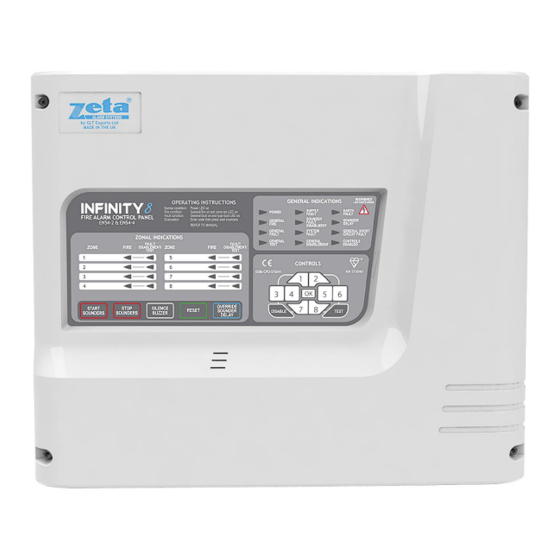
- Page 1 INFINITY 8 INSTALLATION MANUAL FIRE ALARM CONTROL PANEL INSTALLATION MANUAL Approved Document No. GLT-201-7-1 Issue: 1.6 Author: NRPJ Date: 27/7/2012...
-
Page 2: Table Of Contents
INFINITY 8 INSTALLATION MANUAL CONTENTS 1. INTRODUCTION..................................... 1.1 HANDLING THE PCBS..............................1.2 USING THIS MANUAL..............................1.3 ABOUT THE INFINITY FIRE ALARM CONTROL PANEL & INTEGRAL PSE................ 1.4 DESIGNING THE SYSTEM.............................. 1.5 EQUIPMENT GUARANTEE............................1.6 DEFINITION OF ACCESS LEVELS ON THE INFINITY PANEL..................... -
Page 3: Introduction
1.2 USING THIS MANUAL This manual explains, in a step-by-step manner, the procedure for the installation of the Infinity 8 Range of Fire Alarm Control Panels. For full operational and maintenance information, please refer to document GLT.MAN- (USER MANUAL, MAINTENANCE GUIDE &... -
Page 4: Definition Of Access Levels On The Infinity Panel
INFINITY 8 INSTALLATION MANUAL 1.6 DEFINITION OF ACCESS LEVELS ON THE INFINITY PANEL ACCESS LEVEL ACCESSED BY ACCESS METHOD FUNCTIONS ACCESSED General public Default state View panel Override delay (if used) LED test Responsible person Access code entered Start/stop sounders... -
Page 5: First Fix
INFINITY 8 INSTALLATION MANUAL 2. FIRST FIX All wiring must be installed to meet BS5839: Pt1: 2002 and BS 7671 (Wiring Regs) standards. Other National standards of fire alarm system installation should be adhered to where applicable. 2.1 RECOMMENDED CABLE TYPES AND THEIR LIMITATIONS Screened cables should be used throughout the installation to help shield the Panel from outside interference and ensure EMC compatibility. -
Page 6: Sounder Circuit Wiring Diagram
INFINITY 8 INSTALLATION MANUAL page). Other makes of detector will have different connections, but in general they are wired +IN & +OUT to same terminal, -IN to stripe side of continuity diode, -OUT to non-stripe side of continuity diode. Some makes will connect the +ve to a 470R load resistor, or a polarisation diode, to enable the detector to work correctly. - Page 7 INFINITY 8 INSTALLATION MANUAL The termination for the above inputs must be as indicated on the main PCB (See page 15). The Earthing of the cable screens should be as shown on page 9. PAGE 6 Approved Document No. GLT-201-7-1 Issue: 1.6...
-
Page 8: Mounting The Fire Alarm Panel
INFINITY 8 INSTALLATION MANUAL 3. MOUNTING THE FIRE ALARM PANEL It is recommended that the panel’s door be removed to avoid accidental damage. Also, the termination PCB could be removed and stored in a safe place, while fixing the back box to the wall. -
Page 9: Connecting Mains & Battery Power
INFINITY 8 INSTALLATION MANUAL 4. CONNECTING MAINS & BATTERY POWER 4.1 CONNECTING THE MAINS POWER Figure 3: Power Supply PCB layout and Mains connection details Figure 3 4.2 CONNECTING THE BATTERIES Figure 4: Battery location and connection details CAUTION: RISK OF EXPLOSION IF BATTERY IS REPLACED BY AN INCORRECT TYPE. -
Page 10: Field Device Termination
INFINITY 8 INSTALLATION MANUAL 5. FIELD DEVICE TERMINATION 5.1 TERMINATING THE DETECTION AND ALARM (SOUNDER) CIRCUITS All cables entering the enclosure should use cable glands. The Detector and Sounder circuits should be connected to the appropriate connector block on the Termination PCB as shown in Figure 6 below. All screens should be fed through the gland to make electrical contact with it, and be terminated at the brass earthing strip as shown below (see Figure 6) (For detailed detector and alarm circuit wiring diagrams, please refer to pages 6 and 7.) -
Page 11: Sounder Activation Delay
INFINITY 8 INSTALLATION MANUAL 6. SOUNDER ACTIVATION DELAY 6.1 DECIDING TO USE A DELAY A delay of up to ten minutes from the Fire Alarm Panel being triggered, to its Alarm sounder outputs being activated, can be programmed into the panel by the Engineer. This is a particularly useful feature for schools, nightclubs and other public places where the nuisance and panic caused by a false alarm must be avoided. -
Page 12: Zone Disablement
INFINITY 8 INSTALLATION MANUAL 7. ZONE DISABLEMENT 7.1 WHY USE ZONE DISABLEMENT To aid commissioning and assist routine maintenance checks, any of the zones or the sounder circuits can be disabled. When a zone (or sounder cct) is disabled, the panel will not respond to any fault or fire signals it receives from that zone. This might be used if the system requires routine maintenance, and the customer needs the system to continue running, but doesn’t want... -
Page 13: Zone Test
INFINITY 8 INSTALLATION MANUAL 8. ZONE TEST 8.1 WHY USE ZONE TEST To aid commissioning and assist routine maintenance check, a non-latching ‘one man test’ facility is available. When a detector or manual call point is triggered on any zone in Test, the Alarm sounders operate for approximately five seconds on and seven seconds off. -
Page 14: General Fault Finding
INFINITY 8 INSTALLATION MANUAL 9. GENERAL FAULT FINDING 9.1 ZONE FAULTS To assist in fault finding, the infinity panel will display zone faults as follows. The general fault LED will flash if a fault is present. On the first flash, any zones showing O/C will flash. The second time the General fault LED flashes, any zones with a Short Circuit fault will flash in conjunction with the General S/C LED. -
Page 15: Earth Faults
If working on an existing installation, check that the devices are polarised. (See Page 5) Check cable continuity (remove from panel and measure continuity. Should read 10K The Infinity 8 panel uses resettable fuses, which 'open' in the event of a fault, and reset when the fault clears. They do not need replacing. -
Page 16: Standby Battery Calculation
INFINITY 8 INSTALLATION MANUAL 10. STANDBY BATTERY CALCULATION In order to calculate the standby battery size required, the following formula can be used:- Battery Size (Standby time in Amp Hours) = 1.25 x [(T ) + (T x (I Where: = Maximum time in hours required for the alarm [½... -
Page 17: Pcb Termination Connections
INFINITY 8 INSTALLATION MANUAL 11. PCB TERMINATION CONNECTIONS 11.1 CONNECTIONS CONNECTION NO. DESCRIPTION ZONE 1 +&- Connect to Zone 1 ZONE 2 +&- Connect to Zone 2 ZONE 3 +&- Connect to Zone 3 ZONE 4 +&- Connect to Zone 4 ZONE 5 +&-... -
Page 18: Panel Specifications
INFINITY 8 INSTALLATION MANUAL 12. PANEL SPECIFICATIONS 12.1 ENCLOSURE SPECIFICATIONS DESCRIPTION VALUE ENCLOSURE SIZE 364 X 302 X 90 mm TOP CABLE ENTRIES 15 x 20 mm DIA knock outs 12.2 ELECTRICAL SPECIFICATIONS ELECTRICAL DESCRIPTION VALUE MAINS VOLTAGE 100-240V AC +/-10% @ 50/60 Hz... -
Page 19: Engineer Options (8 Way Config Dip Switch)
IN1, IN2, IN4, IN6, IN8 Provided options: Output to fire alarm devices Delays to outputs Test Condition Other Technical Data: See Doc: “Infinity 8 Product file” held by the manufacturer PAGE 18 Approved Document No. GLT-201-7-1 Issue: 1.6 Author: NRPJ...
Need help?
Do you have a question about the INFINITY 8 and is the answer not in the manual?
Questions and answers