Table of Contents
Advertisement
Advertisement
Table of Contents

Subscribe to Our Youtube Channel
Related Manuals for ZyXEL Communications VWG1312-B10A


Summary of Contents for ZyXEL Communications VWG1312-B10A
- Page 1 VMG1312-B10A Wireless N VDSL2 4-ports Gateway with USB Default Login Details IP Address http://192.168.1.1 User Name admin Password 1234 Firmware Version 1.00 Edition 1, 12/2011 www.zyxel.com www.zyxel.com Copyright © 2011 ZyXEL Communications Corporation...
-
Page 3: About This User's Guide
About This User's Guide About This User's Guide Intended Audience This manual is intended for people who want to configure the Device using the web configurator. You should have at least a basic knowledge of TCP/IP networking concepts and topology. Related Documentation •... -
Page 4: Document Conventions
Document Conventions Document Conventions Warnings and Notes These are how warnings and notes are shown in this User’s Guide. Warnings tell you about things that could harm you or your device. Note: Notes tell you other important information (for example, other things you may need to configure or helpful tips) or recommendations. - Page 5 Document Conventions Icons Used in Figures Figures in this User’s Guide may use the following generic icons. The Device icon is not an exact representation of your device. Device Computer Notebook computer Server Firewall Telephone Router Switch VMG1312-B10A User’s Guide...
-
Page 6: Safety Warnings
Safety Warnings Safety Warnings • Do NOT use this product near water, for example, in a wet basement or near a swimming pool. • Do NOT expose your device to dampness, dust or corrosive liquids. • Do NOT store things on the device. •... -
Page 7: Table Of Contents
Contents Overview Contents Overview User’s Guide ............................19 Introducing the Device ..........................21 The Web Configurator ..........................27 Quick Start ...............................35 Tutorials ..............................37 Technical Reference ..........................79 Network Map and Status Screens ......................81 Broadband ...............................85 Wireless ..............................109 Home Networking ..........................141 Routing ..............................163 Quality of Service (QoS) ........................169 Network Address Translation (NAT) ......................187 Dynamic DNS Setup ..........................203 Interface Group .............................207... - Page 8 Contents Overview Troubleshooting ............................291 VMG1312-B10A User’s Guide...
-
Page 9: Table Of Contents
Table of Contents Table of Contents About This User's Guide ........................3 Document Conventions ........................4 Safety Warnings............................6 Contents Overview ..........................7 Table of Contents ..........................9 Part I: User’s Guide ..................19 Chapter 1 Introducing the Device ........................21 1.1 Overview ............................21 1.2 Ways to Manage the Device ......................21 1.3 Good Habits for Managing the Device ....................21 1.4 Applications for the Device .......................22 1.4.1 Internet Access ........................22... - Page 10 Table of Contents Chapter 4 Tutorials ...............................37 4.1 Overview ............................37 4.2 Setting Up an ADSL PPPoE Connection ..................37 4.3 Setting Up a Secure Wireless Network .....................40 4.3.1 Configuring the Wireless Network Settings ................40 4.3.2 Using WPS ..........................42 4.3.3 Without WPS ...........................45 4.4 Setting Up Multiple Wireless Groups ....................46 4.5 Configuring Static Route for Routing to Another Network ..............49 4.6 Configuring QoS Queue and Class Setup ..................52...
- Page 11 Table of Contents 6.5 The 8021x Screen ...........................101 6.5.1 Edit 802.1x Settings .......................102 6.6 Technical Reference ........................102 Chapter 7 Wireless .............................109 7.1 Overview ............................109 7.1.1 What You Can Do in this Chapter ..................109 7.1.2 What You Need to Know ......................110 7.2 The General Screen ........................
- Page 12 Table of Contents 8.5 Installing UPnP in Windows Example .....................149 8.6 Using UPnP in Windows XP Example ....................151 8.7 The Additional Subnet Screen ......................157 8.8 The STB Vendor ID Screen ......................158 8.9 The LAN VLAN Screen ........................159 8.10 Technical Reference ........................159 8.10.1 LANs, WANs and the Device ....................160 8.10.2 DHCP Setup ........................160 8.10.3 DNS Server Addresses .......................160...
- Page 13 Table of Contents 11.3.1 Add New Application ......................192 11.4 The Port Triggering Screen ......................192 11.4.1 Add/Edit Port Triggering Rule .....................194 11.5 The DMZ Screen ...........................195 11.6 The ALG Screen ..........................196 11.7 The Address Mapping Screen .......................196 11.7.1 Add/Edit Address Mapping Rule ..................197 11.8 Technical Reference ........................198 11.8.1 NAT Definitions ........................198 11.8.2 What NAT Does ........................199...
- Page 14 Table of Contents 15.1 Overview ............................219 15.1.1 What You Can Do in this Chapter ..................219 15.1.2 What You Need to Know ......................220 15.2 The Firewall Screen ........................221 15.3 The Service Screen ........................221 15.3.1 Add/Edit a Service ......................222 15.4 The Access Control Screen ......................223 15.4.1 Add/Edit an ACL Rule ......................225 15.5 The DoS Screen ..........................226 Chapter 16...
- Page 15 Table of Contents 20.1.2 What You Need To Know .....................245 20.2 The System Log Screen ........................246 20.3 The Security Log Screen .......................247 Chapter 21 Traffic Status ............................249 21.1 Overview ............................249 21.1.1 What You Can Do in this Chapter ..................249 21.2 The WAN Status Screen .......................249 21.3 The LAN Status Screen .........................251 Chapter 22 ARP Table ............................253...
- Page 16 Table of Contents 28.1 Overview ............................267 28.2 The TR-069 Client Screen ......................267 Chapter 29 TR-064..............................269 29.1 Overview ............................269 29.2 The TR-064 Screen ........................269 Chapter 30 Time Settings ............................271 30.1 Overview ............................271 30.2 The Time Screen ..........................271 Chapter 31 E-mail Notification ..........................275 31.1 Overview ............................275 31.2 The Email Notification Screen .......................275...
- Page 17 Table of Contents 35.5 OAM Ping Test ..........................289 Chapter 36 Troubleshooting..........................291 36.1 Power, Hardware Connections, and LEDs ..................291 36.2 Device Access and Login ......................292 36.3 Internet Access ..........................294 36.4 Wireless Internet Access .......................295 36.5 USB Device Connection ........................296 36.6 UPnP .............................296 Appendix A Setting up Your Computer’s IP Address ...............299 Appendix B IP Addresses and Subnetting..................321 Appendix C Pop-up Windows, JavaScripts and Java Permissions ..........329...
- Page 18 Table of Contents VMG1312-B10A User’s Guide...
-
Page 19: User's Guide
User’s Guide... -
Page 21: Introducing The Device
H A PT ER Introducing the Device 1.1 Overview The VMG1312-B10A is a wireless VDSL router. It has a DSL port for super-fast Internet access over analog (POTS) telephone lines. The Device supports both Packet Transfer Mode (PTM) and Asynchronous Transfer Mode (ATM). It is backward compatible with ADSL, ADSL2 and ADSL2+ in case VDSL is not available. -
Page 22: Applications For The Device
Chapter 1 Introducing the Device 1.4 Applications for the Device Here are some example uses for which the Device is well suited. 1.4.1 Internet Access Your Device provides shared Internet access by connecting the DSL port to the DSL or MODEM jack on a splitter or your telephone jack. -
Page 23: Device's Usb Support
Chapter 1 Introducing the Device 1.4.2 Device’s USB Support The USB port of the Device is used for file-sharing. File Sharing Use the built-in USB 2.0 port to share files on a USB memory stick or a USB hard drive (B). You can connect one USB hard drive to the Device at a time. -
Page 24: Leds (Lights)
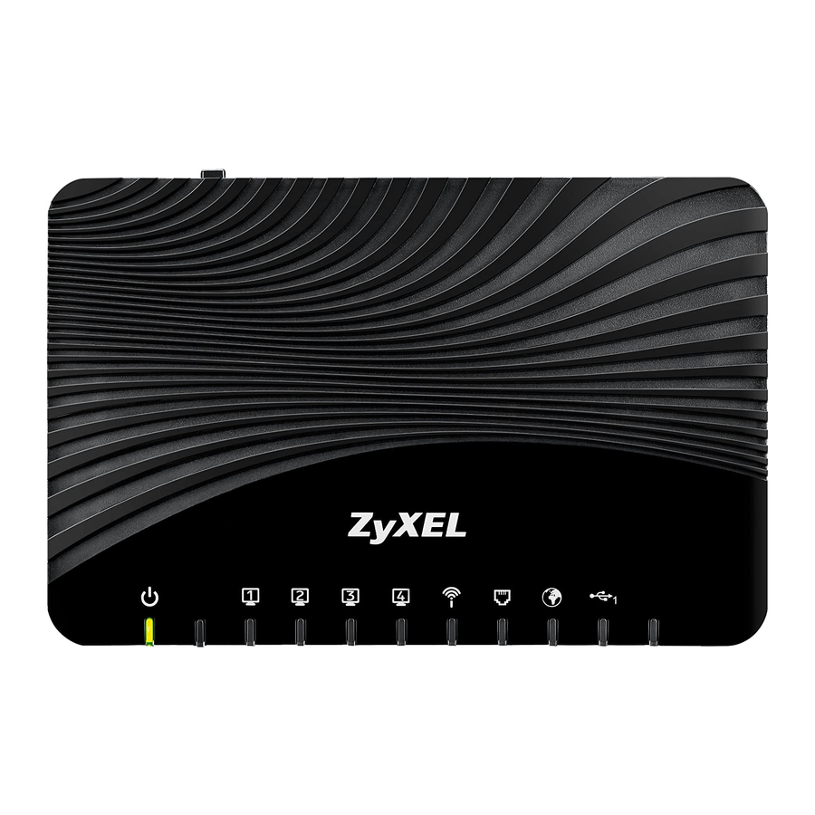
Chapter 1 Introducing the Device 1.5 LEDs (Lights) The following graphic displays the labels of the LEDs. Figure 4 LEDs on the Device None of the LEDs are on if the Device is not receiving power. Table 1 LED Descriptions COLOR STATUS DESCRIPTION... -
Page 25: The Reset Button
Chapter 1 Introducing the Device Table 1 LED Descriptions (continued) COLOR STATUS DESCRIPTION INTERNET Green The Device has an IP connection but no traffic. Your device has a WAN IP address (either static or assigned by a DHCP server), PPP negotiation was successfully completed (if used) and the DSL connection is up. -
Page 26: Using The Wlan/Wps Button
Chapter 1 Introducing the Device You can configure your wireless network in either the built-in Web Configurator, or using the WPS button. Figure 5 Wireless Access Example 1.7.1 Using the WLAN/WPS Button If the wireless network is turned off, press the WLAN/WPS button at the back of the Device for one second. -
Page 27: The Web Configurator
H A PT ER The Web Configurator 2.1 Overview The web configurator is an HTML-based management interface that allows easy device setup and management via Internet browser. Use Internet Explorer 6.0 and later versions or Mozilla Firefox 3 and later versions or Safari 2.0 and later versions. The recommended screen resolution is 1024 by 768 pixels. - Page 28 Chapter 2 The Web Configurator The following screen displays if you have not yet changed your password. It is strongly recommended you change the default password. Enter a new password, retype it to confirm and click Apply; alternatively click Skip to proceed to the main menu if you do not want to change the password now.
-
Page 29: Web Configurator Layout
Chapter 2 The Web Configurator 2.2 Web Configurator Layout Figure 9 Screen Layout As illustrated above, the main screen is divided into these parts: • A - title bar • B - main window • C - navigation panel 2.2.1 Title Bar The title bar provides some icons in the upper right corner. -
Page 30: Main Window
Chapter 2 The Web Configurator 2.2.2 Main Window The main window displays information and configuration fields. It is discussed in the rest of this document. After you click Status on the Connection Status page, the Status screen is displayed. See Chapter 5 on page 82 for more information about the Status screen. - Page 31 Chapter 2 The Web Configurator Table 3 Navigation Panel Summary (continued) LINK FUNCTION Wireless General Use this screen to configure the wireless LAN settings and WLAN authentication/security settings. More AP Use this screen to configure multiple BSSs on the Device. Use this screen to block or allow wireless traffic from wireless devices Authentication of certain SSIDs and MAC addresses to the Device.
- Page 32 Chapter 2 The Web Configurator Table 3 Navigation Panel Summary (continued) LINK FUNCTION USB Device File Sharing Use this screen to enable file sharing via the Device. Media Server Use this screen to use the Device as a media server. Printer Server Use this screen to enable the print server on the Device and get the model name of the associated printer.
- Page 33 Chapter 2 The Web Configurator Table 3 Navigation Panel Summary (continued) LINK FUNCTION Configuration Use this screen to backup and restore your device’s configuration (settings) or reset the factory default settings. Reboot Use this screen to reboot the Device without turning the power off. Diagnostic Ping &...
- Page 34 Chapter 2 The Web Configurator VMG1312-B10A User’s Guide...
-
Page 35: Quick Start
H A PT ER Quick Start 3.1 Overview Use the Quick Start screens to configure the Device’s time zone, basic Internet access, and wireless settings. Note: See the technical reference chapters (starting on page 79) for background information on the features in this chapter. 3.2 Quick Start Setup The Quick Start Wizard appears automatically after login. - Page 36 Chapter 3 Quick Start Enter your Internet connection information in this screen. The screen and fields to enter may vary depending on your current connection type. Click Next. Click Next. Figure 12 Internet Connection Turn the wireless LAN on or off. If you keep it on, record the security settings so you can configure your wireless clients to connect to the Device.
-
Page 37: Tutorials
H A PT ER Tutorials 4.1 Overview This chapter shows you how to use the Device’s various features. • Setting Up an ADSL PPPoE Connection, see page 37 • Setting Up a Secure Wireless Network, see page 40 • Setting Up Multiple Wireless Groups, see page 46 •... - Page 38 Chapter 4 Tutorials Connection Mode Routing Encapsulation PPPoE IPv6/IPv4 Mode IPv4 ATM PVC Configuration VPI/VCI 36/48 Encapsulation Mode LLC/SNAP-Bridging Service Category UBR without PCR Account Information PPP User Name 1234@DSL-Ex.com PPP Password ABCDEF! PPPoE Service Name MyDSL Static IP Address 192.168.1.32 Others PPPoE Passthrough: Disabled...
- Page 39 Chapter 4 Tutorials Click Apply to save your settings. VMG1312-B10A User’s Guide...
-
Page 40: Setting Up A Secure Wireless Network
Chapter 4 Tutorials You should see a summary of your new DSL connection setup in the Broadband screen as follows. Try to connect to a website to see if you have correctly set up your Internet connection. Be sure to contact your service provider for any information you need to configure the WAN screens. - Page 41 Chapter 4 Tutorials Click Network Setting > Wireless to open the General screen. Select More Secure as the security level and WPA-PSK as the security mode. Configure the screen using the provided parameters (see page 40). Click Apply. Go to the Wireless > Others screen and select 802.11b/g/n Mixed in the 802.11 Mode field. Click Apply.
-
Page 42: Using Wps
Chapter 4 Tutorials 4.3.2 Using WPS This section shows you how to set up a wireless network using WPS. It uses the Device as the AP and ZyXEL NWD210N as the wireless client which connects to the notebook. Note: The wireless client must be a WPS-aware device (for example, a WPS USB adapter or PCMCIA card). - Page 43 Chapter 4 Tutorials Note: Your Device has a WPS button located on its front panel as well as a WPS button in its configuration utility. Both buttons have exactly the same function: you can use one or the other. Note: It doesn’t matter which button is pressed first. You must press the second button within two minutes of pressing the first one.
- Page 44 Chapter 4 Tutorials PIN Configuration When you use the PIN configuration method, you need to use both the Device’s web configurator and the wireless client’s utility. Launch your wireless client’s configuration utility. Go to the WPS settings and select the PIN method to get a PIN number.
-
Page 45: Without Wps
Chapter 4 Tutorials The following figure shows you how to set up a wireless network and its security on a Device and a wireless client by using PIN method. Example WPS Process: PIN Method Wireless Client ZyXEL Device WITHIN 2 MINUTES Authentication by PIN SECURITY INFO COMMUNICATION... -
Page 46: Setting Up Multiple Wireless Groups
Chapter 4 Tutorials 4.4 Setting Up Multiple Wireless Groups Company A wants to create different wireless network groups for different types of users as shown in the following figure. Each group has its own SSID and security mode. Company Guest •... - Page 47 Chapter 4 Tutorials Click Network Setting > Wireless to open the General screen. Use this screen to set up the company’s general wireless network group. Configure the screen using the provided parameters and click Apply. Click Network Setting > Wireless > More AP to open the following screen. Click the Edit icon to configure the second wireless network group.
- Page 48 Chapter 4 Tutorials Configure the screen using the provided parameters and click Apply. In the More AP screen, click the Edit icon to configure the third wireless network group. VMG1312-B10A User’s Guide...
-
Page 49: Configuring Static Route For Routing To Another Network
Chapter 4 Tutorials Configure the screen using the provided parameters and click Apply. Check the status of VIP and Guest in the More AP screen. The yellow bulbs signify that the SSIDs are active and ready for wireless access. 4.5 Configuring Static Route for Routing to Another Network In order to extend your Intranet and control traffic flowing directions, you may connect a router to the Device’s LAN. - Page 50 Chapter 4 Tutorials network) to computer B (in N2 network), the traffic is sent to the Device’s WAN default gateway by default. In this case, B will never receive the traffic. You need to specify a static routing rule on the Device to specify R as the router in charge of forwarding traffic to N2.
- Page 51 Chapter 4 Tutorials Table 4 IP Settings in this Tutorial DEVICE / COMPUTER IP ADDRESS R’s N2 192.168.10.2 192.168.10.33 To configure a static route to route traffic from N1 to N2: Log into the Device’s Web Configurator in advanced mode. Click Network Setting >...
-
Page 52: Configuring Qos Queue And Class Setup
Chapter 4 Tutorials 4.6 Configuring QoS Queue and Class Setup This section contains tutorials on how you can configure the QoS screen. Let’s say you are a team leader of a small sales branch office. You want to prioritize e-mail traffic because your task includes sending urgent updates to clients at least twice every hour. - Page 53 Chapter 4 Tutorials Click Network Setting > QoS > General and select Enable. Set your WAN Managed Upstream Bandwidth to 10,000 kbps (or leave this blank to have the Device automatically determine this figure). Click Apply. Tutorial: Advanced > QoS Click Queue Setup >...
- Page 54 Chapter 4 Tutorials Click Class Setup > Add new Classifier to create a new class. Check Active and follow the settings as shown in the screen below. Tutorial: Advanced > QoS > Class Setup Class Name Give a class name to this traffic, such as E-mail in this example. From This is the interface from which the traffic will be coming from.
-
Page 55: Access The Device Using Ddns
Chapter 4 Tutorials This maps e-mail traffic coming from port 25 to the highest priority, which you have created in the previous screen (see the IP Protocol field). This also maps your computer’s IP address and MAC address to the E-mail queue (see the Source fields). Verify that the queue setup works by checking Network Setting >... -
Page 56: Configuring Ddns On Your Device
Chapter 4 Tutorials 4.7.2 Configuring DDNS on Your Device Configure the following settings in the Network Setting > DNS > Dynamic DNS screen. • Select Enable Dynamic DNS. • Select www.DynDNS.com as the service provider. • Type zyxelrouter.dyndns.org in the Host Name field. •... -
Page 57: Configuring The Mac Address Filter
Chapter 4 Tutorials 4.8 Configuring the MAC Address Filter Thomas noticed that his daughter Josephine spends too much time surfing the web and downloading media files. He decided to prevent Josephine from accessing the Internet so that she can concentrate on preparing for her final exams. Josephine’s computer connects wirelessly to the Internet through the Device. -
Page 58: Access Your Shared Files From A Computer
Chapter 4 Tutorials Thomas can also grant access to the computers of other members of his family and friends. However, Josephine and others not listed in this screen will no longer be able to access the Internet through the Device. 4.9 Access Your Shared Files From a Computer Here is how to use an FTP program to access a file storage device connected to the Device’s USB port. -
Page 59: Using The Media Server Feature
Chapter 4 Tutorials 4.10 Using the Media Server Feature Use the media server feature to play files on a computer or on your television (using DMA-2500). This section shows you how the media server feature works using the following media clients: •... - Page 60 Chapter 4 Tutorials Windows Vista Open Windows Media Player and click Library > Media Sharing as follows. Tutorial: Media Sharing using Windows Vista Check Find media that others are sharing in the following screen and click OK. Tutorial: Media Sharing using Windows Vista (2) VMG1312-B10A User’s Guide...
- Page 61 Chapter 4 Tutorials In the Library screen, check the left panel. The Windows Media Player should detect the Device. Tutorial: Media Sharing using Windows Vista (3) The Device displays as a playlist. Clicking on the category icons in the right panel shows you the media files in the USB storage device attached to your Device.
-
Page 62: Using A Digital Media Adapter
Chapter 4 Tutorials Select a category in the left panel and wait for Windows Media Player to connect to the Device. Tutorial: Media Sharing using Windows 7 (2) In the right panel, you should see a list of files available in the USB storage device. Tutorial: Media Sharing using Windows 7 (2) 4.10.3 Using a Digital Media Adapter This section shows you how you can use the Device with a ZyXEL DMA-2500 to play media files... - Page 63 Chapter 4 Tutorials Connect the DMA-2500 to an available LAN port in your Device. Tutorial: Media Server Setup (Using DMA) USB Storage Device DMA-2500 ZyXEL Device Turn on the TV and wait for the DMA-2500 Home screen to appear. Using the remote control, go to MyMedia to open the following screen.
-
Page 64: Using The Print Server Feature
Chapter 4 Tutorials 4.11 Using the Print Server Feature In this section you can: • Configure a TCP/IP Printer Port • Add a New Printer Using Windows • Add a New Printer Using Macintosh OS X Configure a TCP/IP Printer Port This example shows how you can configure a TCP/IP printer port. - Page 65 Chapter 4 Tutorials Right click on your printer and select Properties. Tutorial: Open Printer Properties Select the Ports tab and click Add Port... Tutorial: Printer Properties Window A Printer Ports window appears. Select Standard TCP/IP Port and click New Port... Tutorial: Add a Port Window VMG1312-B10A User’s Guide...
- Page 66 Chapter 4 Tutorials Add Standard TCP/IP Printer Port Wizard window opens up. Click Next to start configuring the printer port. Tutorial: Add a Port Wizard Enter the IP address of the Device to which the printer is connected in the Printer Name or IP Address: field.
- Page 67 Chapter 4 Tutorials Select Custom under Device Type and click Settings. Tutorial: Custom Port Settings Confirm the IP address of the Device in the IP Address field. 10 Select Raw under Protocol. 11 The Port Number is automatically configured as 9100. Click OK. Tutorial: Custom Port Settings VMG1312-B10A User’s Guide...
- Page 68 Chapter 4 Tutorials 12 Continue through the wizard, apply your settings and close the wizard window. Tutorial: Finish Adding the TCP/IP Port 13 Repeat steps 1 to 12 to add this printer to other computers on your network. Add a New Printer Using Windows This example shows how to connect a printer to your Device using the Windows XP Professional operating system.
- Page 69 Chapter 4 Tutorials Click Start > Control Panel > Printers and Faxes to open the Printers and Faxes screen. Click Add a Printer. Tutorial: Printers Folder The Add Printer Wizard screen displays. Click Next. Tutorial: Add Printer Wizard: Welcome VMG1312-B10A User’s Guide...
- Page 70 Chapter 4 Tutorials Select Local printer attached to this computer and click Next. Tutorial: Add Printer Wizard: Local or Network Printer Select Create a new port and Standard TCP/IP Port. Click Next. Tutorial: Add Printer Wizard: Select the Printer Port VMG1312-B10A User’s Guide...
- Page 71 Chapter 4 Tutorials Add Standard TCP/IP Printer Port Wizard window opens up. Click Next to start configuring the printer port. Tutorial: Add a Port Wizard Enter the IP address of the Device to which the printer is connected in the Printer Name or IP Address: field.
- Page 72 Chapter 4 Tutorials Select Custom under Device Type and click Settings. Tutorial: Custom Port Settings Confirm the IP address of the Device in the Printer Name or IP Address field. Select Raw under Protocol. 10 The Port Number is automatically configured as 9100. Click OK to go back to the previous screen and click Next.
- Page 73 Chapter 4 Tutorials 11 Click Finish to close the wizard window. Tutorial: Finish Adding the TCP/IP Port 12 Select the make of the printer that you want to connect to the print server in the Manufacturer list of printers. 13 Select the printer model from the list of Printers. 14 If your printer is not displayed in the list of Printers, you can insert the printer driver installation CD/disk or download the driver file to your computer, click Have Disk…...
- Page 74 Chapter 4 Tutorials 16 If the following screen displays, select Keep existing driver radio button and click Next if you already have a printer driver installed on your computer and you do not want to change it. Otherwise, select Replace existing driver to replace it with the new driver you selected in the previous screen and click Next.
- Page 75 Chapter 4 Tutorials 18 The Device is a print server itself and you do not need to have your computer act as a print server by sharing the printer with other users in the same network; just select Do not share this printer and click Next to proceed to the following screen.
- Page 76 Chapter 4 Tutorials 20 The following screen shows your current printer settings. Select Finish to complete adding a new printer. Tutorial: Add Printer Wizard Complete Add a New Printer Using Macintosh OS X Complete the following steps to set up a print server driver on your Macintosh computer. Click the Print Center icon located in the Macintosh Dock (a place holding a series of icons/ shortcuts at the bottom of the desktop).
- Page 77 Chapter 4 Tutorials Double-click the Utilities folder. Tutorial: Applications Folder Double-click the Print Center icon. Tutorial: Utilities Folder Click the Add icon at the top of the screen. Tutorial: Printer List Folder Set up your printer in the Printer List configuration screen. Select IP Printing from the drop- down list box.
- Page 78 Chapter 4 Tutorials 11 Select your Printer Model from the drop-down list box. If the printer's model is not listed, select Generic. Tutorial: Printer Configuration 12 Click Add to select a printer model, save and close the Printer List configuration screen. Tutorial: Printer Model 13 The Name LP1 on 192.168.1.1 displays in the Printer List field.
-
Page 79: Technical Reference
Technical Reference... -
Page 81: Network Map And Status Screens
H A PT ER Network Map and Status Screens 5.1 Overview After you log into the Web Configurator, the Network Map screen appears. This shows the network connection status of the Device and clients connected to it. You can use the Status screen to look at the current status of the Device, system resources, and interfaces (LAN, WAN, and WLAN). -
Page 82: The Status Screen
Chapter 5 Network Map and Status Screens In Icon Mode, if you want to view information about a client, click the client’s name and Info. Click the IP address if you want to change it. If you want to change the name or icon of the client, click Change icon/name. - Page 83 Chapter 5 Network Map and Status Screens Table 5 Status Screen (continued) LABEL DESCRIPTION Model This shows the model number of your Device. Number Firmware This is the current version of the firmware inside the Device. Version WAN Information (These fields display when you have a WAN connection.) WAN Type This field displays the current WAN connection type.
- Page 84 Chapter 5 Network Map and Status Screens Table 5 Status Screen (continued) LABEL DESCRIPTION CPU Usage This field displays what percentage of the Device’s processing ability is currently used. When this percentage is close to 100%, the Device is running at full load, and the throughput is not going to improve anymore.
-
Page 85: Broadband
H A PT ER Broadband 6.1 Overview This chapter discusses the Device’s Broadband screens. Use these screens to configure your Device for Internet access. A WAN (Wide Area Network) connection is an outside connection to another network or the Internet. It connects your private networks, such as a LAN (Local Area Network) and other networks, so that a computer in one location can communicate with computers in other locations. -
Page 86: What You Need To Know
Chapter 6 Broadband • Use the Advanced screen to enable or disable PTM over ADSL, Annex M, and DSL PhyR functions (Section 6.4 on page 100). • Use the 8021x screen to view and configure the IEEE 802.1x settings on the Device (Section 6.5 on page 101). - Page 87 Chapter 6 Broadband Service) can be guaranteed. ATM uses a connection-oriented model and establishes a virtual circuit (VC) between Finding Out More Packet Transfer Mode (PTM) is packet-oriented and supported by the VDSL2 standard. In PTM, packets are encapsulated directly in the High-level Data Link Control (HDLC) frames. It is designed to provide a low-overhead, transparent way of transporting packets over DSL links, as an alternative to ATM.
-
Page 88: Before You Begin
Chapter 6 Broadband IPv6 Subnet Masking Both an IPv6 address and IPv6 subnet mask compose of 128-bit binary digits, which are divided into eight 16-bit blocks and written in hexadecimal notation. Hexadecimal uses four bits for each character (1 ~ 10, A ~ F). Each block’s 16 bits are then represented by four hexadecimal characters. -
Page 89: Add/Edit Internet Connection
Chapter 6 Broadband Table 7 Network Setting > Broadband (continued) LABEL DESCRIPTION MLD Proxy This shows whether Multicast Listener Discovery (MLD) is activated or not for this connection. MLD is not available when the connection uses the bridging service. Modify Click the Edit icon to configure the WAN connection. - Page 90 Chapter 6 Broadband The following table describes the labels in this screen. Table 8 Routing Mode LABEL DESCRIPTION General Active Select this to activate the WAN configuration settings. Name Specify a descriptive name for this connection. Type Select whether it is an ADSL/VDSL over PTM or ADSL over ATM connection. Mode Select Routing if your ISP give you one IP address only and you want multiple computers to share an Internet account.
- Page 91 Chapter 6 Broadband Table 8 Routing Mode (continued) LABEL DESCRIPTION Service Select UBR Without PCR or UBR With PCR for applications that are non-time sensitive, Category such as e-mail. Select CBR (Continuous Bit Rate) to specify fixed (always-on) bandwidth for voice or data traffic.
- Page 92 Chapter 6 Broadband Table 8 Routing Mode (continued) LABEL DESCRIPTION Gateway IP Enter the gateway IP address provided by your ISP. Address Routing Feature This is available only when you select IPv4 Only or IPv6/IPv4 DualStack in the IPv6/ IPv4 Mode field. NAT Enable Select this option to activate NAT on this connection.
-
Page 93: Bridge Mode
Chapter 6 Broadband Table 8 Routing Mode (continued) LABEL DESCRIPTION IPv6 DNS Select Dynamic to have the Device get the IPv6 DNS server addresses from the ISP automatically. Select Static to have the Device use the IPv6 DNS server addresses you configure manually. - Page 94 Chapter 6 Broadband If you select ADSL/VDSL over PTM as the interface type, the following screen appears. Figure 21 Bridge Mode (ADSL/VDSL over PTM) The following table describes the fields in this screen. Table 9 Bridge Mode (ADSL/VDSL over PTM) LABEL DESCRIPTION General...
- Page 95 Chapter 6 Broadband If you select ADSL over ATM as the interface type, the following screen appears. Figure 22 Bridge Mode (ADSL over ATM) The following table describes the fields in this screen. Table 10 Bridge Mode (ADSL over ATM) LABEL DESCRIPTION General...
-
Page 96: The 3G Backup Screen
Chapter 6 Broadband Table 10 Bridge Mode (ADSL over ATM) (continued) LABEL DESCRIPTION Encapsulation Select the method of multiplexing used by your ISP from the drop-down list box. Choices Mode are: • LLC/SNAP-BRIDGING: In LCC encapsulation, bridged PDUs are encapsulated by identifying the type of the bridged media in the SNAP header. - Page 97 Chapter 6 Broadband Note: The actual data rate you obtain varies depending the 3G card you use, the signal strength to the service provider’s base station, and so on. Figure 23 Network Setting > Broadband > 3G Backup The following table describes the labels in this screen. Table 11 Network Setting >...
- Page 98 Chapter 6 Broadband Table 11 Network Setting > Broadband > 3G Backup (continued) LABEL DESCRIPTION Username Type the user name (of up to 64 ASCII printable characters) given to you by your service provider. Password Type the password (of up to 64 ASCII printable characters) associated with the user name above.
- Page 99 Chapter 6 Broadband Table 11 Network Setting > Broadband > 3G Backup (continued) LABEL DESCRIPTION Data Budget Select this and specify how much downstream and/or upstream data (in Mega bytes) can be (Mbytes) transmitted via the 3G connection within one month. Select Download/Upload to set a limit on the total traffic in both directions.
-
Page 100: The Advanced Screen
Chapter 6 Broadband Table 11 Network Setting > Broadband > 3G Backup (continued) LABEL DESCRIPTION Apply Click Apply to save your changes back to the Device. Cancel Click Cancel to return to the previous configuration. 6.4 The Advanced Screen Use the Advanced screen to enable or disable PTM over ADSL, Annex M, and DSL PhyR functions. The Device supports the PhyR retransmission scheme. -
Page 101: The 8021X Screen
Chapter 6 Broadband 6.5 The 8021x Screen You can view and configure the 802.1x authentication settings in the 8021x screen. Click Network Setting > Broadband > 8021x to display the following screen. Figure 25 Network Setting > Broadband > 8021x The following table describes the labels in this screen. -
Page 102: Edit 802.1X Settings
Chapter 6 Broadband 6.5.1 Edit 802.1x Settings Use this screen to edit a 802.1x authentication’s settings. Click the Edit icon next to the rule you want to edit. The screen shown next appears. Figure 26 802.1x: Add/Edit The following table describes the labels in this screen. Table 14 802.1x: Add/Edit LABEL DESCRIPTION... - Page 103 Chapter 6 Broadband Encapsulation Be sure to use the encapsulation method required by your ISP. The Device can work in bridge mode or routing mode. When the Device is in routing mode, it supports the following methods. IP over Ethernet IP over Ethernet (IPoE) is an alternative to PPPoE.
- Page 104 Chapter 6 Broadband Multiplexing There are two conventions to identify what protocols the virtual circuit (VC) is carrying. Be sure to use the multiplexing method required by your ISP. VC-based Multiplexing In this case, by prior mutual agreement, each protocol is assigned to a specific virtual circuit; for example, VC1 carries IP, etc.
- Page 105 Chapter 6 Broadband The following figure illustrates the relationship between PCR, SCR and MBS. Figure 27 Example of Traffic Shaping ATM Traffic Classes These are the basic ATM traffic classes defined by the ATM Forum Traffic Management 4.0 Specification. Constant Bit Rate (CBR) Constant Bit Rate (CBR) provides fixed bandwidth that is always available even if no data is being sent.
- Page 106 Chapter 6 Broadband IP Address Assignment A static IP is a fixed IP that your ISP gives you. A dynamic IP is not fixed; the ISP assigns you a different one each time. The Single User Account feature can be enabled or disabled if you have either a dynamic or static IP.
- Page 107 Chapter 6 Broadband Multicast IP packets are transmitted in either one of two ways - Unicast (1 sender - 1 recipient) or Broadcast (1 sender - everybody on the network). Multicast delivers IP packets to a group of hosts on the network - not everybody and not just 1.
- Page 108 Chapter 6 Broadband compose the network address. The prefix length is written as “/x” where x is a number. For example, 2001:db8:1a2b:15::1a2f:0/32 means that the first 32 bits (2001:db8) is the subnet prefix. VMG1312-B10A User’s Guide...
-
Page 109: Wireless
H A PT ER Wireless 7.1 Overview This chapter describes the Device’s Network Setting > Wireless screens. Use these screens to set up your Device’s wireless connection. 7.1.1 What You Can Do in this Chapter This section describes the Device’s Wireless screens. Use these screens to set up your Device’s wireless connection. -
Page 110: What You Need To Know
Chapter 7 Wireless 7.1.2 What You Need to Know Wireless Basics “Wireless” is essentially radio communication. In the same way that walkie-talkie radios send and receive information over the airwaves, wireless networking devices exchange information with one another. A wireless networking device is just like a radio that lets your computer exchange information with radios attached to other computers. - Page 111 Chapter 7 Wireless Click Network Setting > Wireless to open the General screen. Figure 28 Network Setting > Wireless > General The following table describes the general wireless LAN labels in this screen. Table 15 Network Setting > Wireless > General LABEL DESCRIPTION Wireless Network Setup...
-
Page 112: No Security
Chapter 7 Wireless Table 15 Network Setting > Wireless > General (continued) LABEL DESCRIPTION Control This is available for some regions when you select a specific channel and set the Bandwidth Sideband field to 40MHz. Set whether the control channel (set in the Channel field) should be in the Lower or Upper range of channel bands. -
Page 113: Basic (Wep Encryption)
Chapter 7 Wireless Note: If you do not enable any wireless security on your Device, your network is accessible to any wireless networking device that is within range. Figure 29 Wireless > General: No Security The following table describes the labels in this screen. Table 16 Wireless >... - Page 114 Chapter 7 Wireless In order to configure and enable WEP encryption, click Network Setting > Wireless to display the General screen, then select Basic as the security level. Figure 30 Wireless > General: Basic (WEP) The following table describes the labels in this screen. Table 17 Wireless >...
-
Page 115: More Secure (Wpa(2)-Psk)
Chapter 7 Wireless 7.2.3 More Secure (WPA(2)-PSK) The WPA-PSK security mode provides both improved data encryption and user authentication over WEP. Using a Pre-Shared Key (PSK), both the Device and the connecting client share a common password in order to validate the connection. This type of encryption, while robust, is not as strong as WPA, WPA2 or even WPA2-PSK. -
Page 116: Wpa(2) Authentication
Chapter 7 Wireless Table 18 Wireless > General: More Secure: WPA(2)-PSK (continued) LABEL DESCRIPTION Encryption Select the encryption type (AES or TKIP+AES) for data encryption. Select AES if your wireless clients can all use AES. Select TKIP+AES to allow the wireless clients to use either TKIP or AES. Group Key The Group Key Update Timer is the rate at which the RADIUS server sends a new group Update Timer... -
Page 117: The More Ap Screen
Chapter 7 Wireless Table 19 Wireless > General: More Secure: WPA(2) (continued) LABEL DESCRIPTION IP Address Enter the IP address of the external authentication server in dotted decimal notation. Port Enter the port number of the external authentication server. The default port number is Number 1812. -
Page 118: Edit More Ap
Chapter 7 Wireless The following table describes the labels in this screen. Table 20 Network Setting > Wireless > More AP LABEL DESCRIPTION This is the index number of the entry. Status This field indicates whether this SSID is active. A yellow bulb signifies that this SSID is active. -
Page 119: Mac Authentication
Chapter 7 Wireless Table 21 More AP: Edit (continued) LABEL DESCRIPTION Passphrase If you set security for the wireless LAN and have the Device generate a password, the Type setting in this field determines how the Device generates the password. Select None to set the Device’s password generation to not be based on a passphrase. -
Page 120: The Wps Screen
Chapter 7 Wireless Use this screen to view your Device’s MAC filter settings and add new MAC filter rules. Click Network Setting > Wireless > MAC Authentication. The screen appears as shown. Figure 35 Wireless > MAC Authentication The following table describes the labels in this screen. Table 22 Wireless >... - Page 121 Chapter 7 Wireless Note: The Device applies the security settings of the SSID1 profile (see Section 7.2 on page 110). If you want to use the WPS feature, make sure you have set the security mode of SSID1 to WPA-PSK, WPA2-PSK or No Security. Click Network Setting >...
-
Page 122: The Wmm Screen
Chapter 7 Wireless Table 23 Network Setting > Wireless > WPS (continued) LABEL DESCRIPTION Release The default WPS status is configured. Configuratio Click this button to remove all configured wireless and wireless security settings for WPS connections on the Device. Generate The PIN (Personal Identification Number) of the Device is shown here. -
Page 123: The Wds Screen
Chapter 7 Wireless 7.7 The WDS Screen An AP using the Wireless Distribution System (WDS) can function as a wireless network bridge allowing you to wirelessly connect two wired network segments. The WDS screen allows you to configure the Device to connect to two or more APs wirelessly when WDS is enabled. Use this screen to set up your WDS (Wireless Distribution System) links between the Device and other wireless APs. -
Page 124: Wds Scan
Chapter 7 Wireless Table 25 Network Setting > Wireless > WDS (continued) LABEL DESCRIPTION Remote Bridge You can enter the MAC address of the peer device by clicking the Edit icon under Modify. MAC Address This is the index number of the entry. MAC Address This shows the MAC address of the peer device. -
Page 125: The Others Screen
Chapter 7 Wireless 7.8 The Others Screen Use this screen to configure advanced wireless settings. Click Network Setting > Wireless > Others. The screen appears as shown. Section 7.10.2 on page 129 for detailed definitions of the terms listed in this screen. Figure 40 Network Setting >... - Page 126 Chapter 7 Wireless Table 27 Network Setting > Wireless > Others (continued) LABEL DESCRIPTION 802.11 Mode Select 802.11b Only to allow only IEEE 802.11b compliant WLAN devices to associate with the Device. Select 802.11g Only to allow only IEEE 802.11g compliant WLAN devices to associate with the Device.
-
Page 127: The Channel Status Screen
Chapter 7 Wireless 7.9 The Channel Status Screen Use the Channel Status screen to scan wireless LAN channel noises and view the results. Click Network Setting > Wireless > Channel Status. The screen appears as shown. Click Scan to scan the wireless LAN channels. You can view the results in the Channel Scan Result section. Figure 41 Network Setting >... - Page 128 Chapter 7 Wireless • An “infrastructure” type of network has one or more access points and one or more wireless clients. The wireless clients connect to the access points. • An “ad-hoc” type of network is one in which there is no access point. Wireless clients connect to one another in order to exchange information.
-
Page 129: Additional Wireless Terms
Chapter 7 Wireless variety of networks to exist in the same place without interfering with one another. When you create a network, you must select a channel to use. Since the available unlicensed spectrum varies from one country to another, the number of available channels also varies. - Page 130 Chapter 7 Wireless Because of the damage that can be done by a malicious attacker, it’s not just people who have sensitive information on their network who should use security. Everybody who uses any wireless network should ensure that effective security is in place. A good way to come up with effective security keys, passwords and so on is to use obscure information that you personally will easily remember, and to enter it in a way that appears random and does not include real words.
-
Page 131: Signal Problems
Chapter 7 Wireless wireless users to get a valid user name and password. Then, they can use that user name and password to use the wireless network. 7.10.3.4 Encryption Wireless networks can use encryption to protect the information that is sent in the wireless network. -
Page 132: Bss
Chapter 7 Wireless coincidental emitters such as electric motors or microwaves. Problems with absorption occur when physical objects (such as thick walls) are between the two radios, muffling the signal. 7.10.5 BSS A Basic Service Set (BSS) exists when all communications between wireless stations or between a wireless station and a wired network client go through one access point (AP). -
Page 133: Preamble Type
Chapter 7 Wireless • You must use different keys for different BSSs. If two wireless devices have different BSSIDs (they are in different BSSs), but have the same keys, they may hear each other’s communications (but not communicate with each other). •... - Page 134 Chapter 7 Wireless WPS allows you to quickly set up a wireless network with strong security, without having to configure security settings manually. Each WPS connection works between two devices. Both devices must support WPS (check each device’s documentation to make sure). Depending on the devices you have, you can either press a button (on the device itself, or in its configuration utility) or enter a PIN (a unique Personal Identification Number that allows one device to authenticate the other) in each of the two devices.
- Page 135 Chapter 7 Wireless Ensure WPS is enabled on both devices. Access the WPS section of the AP’s configuration interface. See the device’s User’s Guide for how to do this. Look for the client’s WPS PIN; it will be displayed either on the device, or in the WPS section of the client’s configuration interface (see the device’s User’s Guide for how to find the WPS PIN - for the Device, see Section 7.5 on page...
- Page 136 Chapter 7 Wireless The following figure shows a WPS-enabled wireless client (installed in a notebook computer) connecting to the WPS-enabled AP via the PIN method. Figure 45 Example WPS Process: PIN Method ENROLLEE REGISTRAR This device’s WPS PIN: 123456 Enter WPS PIN from other device: START START...
- Page 137 Chapter 7 Wireless The following figure shows a WPS-enabled client (installed in a notebook computer) connecting to a WPS-enabled access point. Figure 46 How WPS works ACTIVATE ACTIVATE WITHIN 2 MINUTES WPS HANDSHAKE ENROLLEE REGISTRAR SECURE TUNNEL SECURITY INFO COMMUNICATION The roles of registrar and enrollee last only as long as the WPS setup process is active (two minutes).
- Page 138 Chapter 7 Wireless is the registrar, and Client 1 is the enrollee. The registrar randomly generates the security information to set up the network, since it is unconfigured and has no existing information. Figure 47 WPS: Example Network Step 1 ENROLLEE REGISTRAR SECURITY INFO...
- Page 139 Chapter 7 Wireless In step 3, you add another access point (AP2) to your network. AP2 is out of range of AP1, so you cannot use AP1 for the WPS handshake with the new access point. However, you know that Client 2 supports the registrar function, so you use it to perform the WPS handshake instead.
- Page 140 Chapter 7 Wireless • When you use the PBC method, there is a short period (from the moment you press the button on one device to the moment you press the button on the other device) when any WPS-enabled device could join the network. This is because the registrar has no way of identifying the “correct”...
-
Page 141: Home Networking
H A PT ER Home Networking 8.1 Overview A Local Area Network (LAN) is a shared communication system to which many networking devices are connected. It is usually located in one immediate area such as a building or floor of a building. Use the LAN screens to help you configure a LAN DHCP server and manage IP addresses. -
Page 142: What You Need To Know
Chapter 8 Home Networking 8.1.2 What You Need To Know 8.1.2.1 About LAN IP Address IP addresses identify individual devices on a network. Every networking device (including computers, servers, routers, printers, etc.) needs an IP address to communicate across the network. -
Page 143: Before You Begin
Chapter 8 Home Networking • Assigning lease times to mappings Windows Messenger is an example of an application that supports NAT traversal and UPnP. See the Chapter 11 on page 187 for more information on NAT. Cautions with UPnP The automated nature of NAT traversal applications in establishing their own services and opening firewall ports may present network security issues. - Page 144 Chapter 8 Home Networking Click Apply to save your settings. Figure 50 Network Setting > Home Networking > LAN Setup The following table describes the fields in this screen. Table 30 Network Setting > Home Networking > LAN Setup LABEL DESCRIPTION Interface Group Group Name...
- Page 145 Chapter 8 Home Networking Table 30 Network Setting > Home Networking > LAN Setup (continued) LABEL DESCRIPTION DHCP Relay This field is only available when you select DHCP Relay in the DHCP field. Server Address IP Address Enter the IP address of the actual remote DHCP server in this field. IP Addressing This field is only available when you select Enable in the DHCP field.
-
Page 146: The Static Dhcp Screen
Chapter 8 Home Networking Table 30 Network Setting > Home Networking > LAN Setup (continued) LABEL DESCRIPTION LAN IPv6 Select how you want to obtain an IPv6 address: Address Assign • stateless + DNS send by RADVD: The Device uses IPv6 stateless autoconfiguration. Setup RADVD (Router Advertisement Daemon) is enabled to have the Device send IPv6 prefix information in router advertisements periodically and in response to router solicitations. - Page 147 Chapter 8 Home Networking Use this screen to change your Device’s static DHCP settings. Click Network Setting > Home Networking > Static DHCP to open the following screen. Figure 51 Network Setting > Home Networking > Static DHCP The following table describes the labels in this screen. Table 31 Network Setting >...
-
Page 148: The Upnp Screen
Chapter 8 Home Networking Table 32 Static DHCP: Add/Edit (continued) LABEL DESCRIPTION Select Device Info If you select Manual Input, you can manually type in the MAC address and IP address of a computer on your LAN. You can also choose the name of a computer from the drop list and have the MAC Address and IP Address auto-detected. -
Page 149: Installing Upnp In Windows Example
Chapter 8 Home Networking Table 33 Network Setting > Home Networking > UPnP (continued) LABEL DESCRIPTION Apply Click Apply to save your changes. Cancel Click Cancel to exit this screen without saving. 8.5 Installing UPnP in Windows Example This section shows how to install UPnP in Windows Me and Windows XP. Installing UPnP in Windows Me Follow the steps below to install the UPnP in Windows Me. - Page 150 Chapter 8 Home Networking In the Communications window, select the Universal Plug and Play check box in the Components selection box. Add/Remove Programs: Windows Setup: Communication: Components Click OK to go back to the Add/Remove Programs Properties window and click Next. Restart the computer when prompted.
-
Page 151: Using Upnp In Windows Xp Example
Chapter 8 Home Networking The Windows Optional Networking Components Wizard window displays. Select Networking Service in the Components selection box and click Details. Windows Optional Networking Components Wizard In the Networking Services window, select the Universal Plug and Play check box. Networking Services Click OK to go back to the Windows Optional Networking Component Wizard window and click Next. - Page 152 Chapter 8 Home Networking Make sure the computer is connected to a LAN port of the Device. Turn on your computer and the Device. Auto-discover Your UPnP-enabled Network Device Click Start and Control Panel. Double-click Network Connections. An icon displays under Internet Gateway.
- Page 153 Chapter 8 Home Networking You may edit or delete the port mappings or click Add to manually add port mappings. Internet Connection Properties: Advanced Settings Internet Connection Properties: Advanced Settings: Add When the UPnP-enabled device is disconnected from your computer, all port mappings will be deleted automatically.
- Page 154 Chapter 8 Home Networking Double-click on the icon to display your current Internet connection status. Internet Connection Status Web Configurator Easy Access With UPnP, you can access the web-based configurator on the Device without finding out the IP address of the Device first. This comes helpful if you do not know the IP address of the Device. Follow the steps below to access the web configurator.
- Page 155 Chapter 8 Home Networking Select My Network Places under Other Places. Network Connections An icon with the description for each UPnP-enabled device displays under Local Network. Right-click on the icon for your Device and select Invoke. The web configurator login screen displays.
- Page 156 Chapter 8 Home Networking Right-click on the icon for your Device and select Properties. A properties window displays with basic information about the Device. Network Connections: My Network Places: Properties: Example VMG1312-B10A User’s Guide...
-
Page 157: The Additional Subnet Screen
Chapter 8 Home Networking 8.7 The Additional Subnet Screen Use the Additional Subnet screen to configure IP alias and public static IP. IP alias allows you to partition a physical network into different logical networks over the same Ethernet interface. The Device supports multiple logical LAN interfaces via its physical Ethernet interface with the Device itself as the gateway for the LAN network. -
Page 158: The Stb Vendor Id Screen
Chapter 8 Home Networking Table 34 Network Setting > Home Networking > Additional Subnet (continued) LABEL DESCRIPTION Offer Public IP Select the checkbox to enable the Device to provide public IP addresses by DHCP server. by DHCP Enable ARP Select the checkbox to enable the ARP (Address Resolution Protocol) proxy. Proxy Apply Click Apply to save your changes. -
Page 159: The Lan Vlan Screen
Chapter 8 Home Networking 8.9 The LAN VLAN Screen Click Network Setting > Home Networking > LAN VLAN to open this screen. Use this screen to control the VLAN ID and IEEE 802.1p priority tags of traffic sent out through individual LAN ports. Figure 56 Network Setting >... -
Page 160: Lans, Wans And The Device
Chapter 8 Home Networking 8.10.1 LANs, WANs and the Device The actual physical connection determines whether the Device ports are LAN or WAN ports. There are two separate IP networks, one inside the LAN network and the other outside the WAN network as shown next. -
Page 161: Lan Tcp/Ip
Chapter 8 Home Networking • Some ISPs choose to disseminate the DNS server addresses using the DNS server extensions of IPCP (IP Control Protocol) after the connection is up. If your ISP did not give you explicit DNS servers, chances are the DNS servers are conveyed through IPCP negotiation. The Device supports the IPCP DNS server extensions through the DNS proxy feature. - Page 162 Chapter 8 Home Networking You can obtain your IP address from the IANA, from an ISP or it can be assigned from a private network. If you belong to a small organization and your Internet access is through an ISP, the ISP can provide you with the Internet addresses for your local networks.
-
Page 163: Routing
H A PT ER Routing 9.1 Overview The Device usually uses the default gateway to route outbound traffic from computers on the LAN to the Internet. To have the Device send data to devices not reachable through the default gateway, use static routes. -
Page 164: The Routing Screen
Chapter 9 Routing 9.2 The Routing Screen Use this screen to view and configure the static route rules on the Device. Click Network Setting > Routing > Static Route to open the following screen. Figure 59 Network Setting > Routing > Static Route The following table describes the labels in this screen. -
Page 165: Add/Edit Static Route
Chapter 9 Routing 9.2.1 Add/Edit Static Route Use this screen to add or edit a static route. Click Add new static route in the Routing screen or the Edit icon next to the static route you want to edit. The screen shown next appears. Figure 60 Routing: Add/Edit The following table describes the labels in this screen. - Page 166 Chapter 9 Routing You can use source-based policy forwarding to direct traffic from different users through different connections or distribute traffic among multiple paths for load sharing. The Policy Forwarding screen let you view and configure routing policies on the Device. Click Network Setting >...
-
Page 167: Add/Edit Policy Forwarding
Chapter 9 Routing 9.3.1 Add/Edit Policy Forwarding Click Add new Policy Forward Rule in the Policy Forwarding screen or click the Edit icon next to a policy. Use this screen to configure the required information for a policy route. Figure 62 Policy Forwarding: Add/Edit The following table describes the labels in this screen. - Page 168 Chapter 9 Routing VMG1312-B10A User’s Guide...
-
Page 169: Quality Of Service (Qos)
HAPTER Quality of Service (QoS) 10.1 Overview Quality of Service (QoS) refers to both a network’s ability to deliver data with minimum delay, and the networking methods used to control the use of bandwidth. Without QoS, all traffic data is equally likely to be dropped when the network is congested. -
Page 170: What You Need To Know
Chapter 10 Quality of Service (QoS) 10.2 What You Need to Know The following terms and concepts may help as you read through this chapter. QoS versus Cos QoS is used to prioritize source-to-destination traffic flows. All packets in the same flow are given the same priority. -
Page 171: The Quality Of Service General Screen
Chapter 10 Quality of Service (QoS) Traffic Policing Traffic policing is the limiting of the input or output transmission rate of a class of traffic on the basis of user-defined criteria. Traffic policing methods measure traffic flows against user-defined criteria and identify it as either conforming, exceeding or violating the criteria. Traffic Rate Traffic Rate Time... -
Page 172: The Queue Setup Screen
Chapter 10 Quality of Service (QoS) The following table describes the labels in this screen. Table 41 Network Setting > QoS > General LABEL DESCRIPTION Select the Enable check box to turn on QoS to improve your network performance. WAN Managed Enter the amount of upstream bandwidth for the WAN interfaces that you want to allocate Upstream using QoS. - Page 173 Chapter 10 Quality of Service (QoS) Use this screen to configure QoS queue assignment. Figure 64 Network Setting > QoS > Queue Setup The following table describes the labels in this screen. Table 42 Network Setting > QoS > Queue Setup LABEL DESCRIPTION Add new Queue...
-
Page 174: Adding A Qos Queue
Chapter 10 Quality of Service (QoS) 10.4.1 Adding a QoS Queue Click Add new Queue or the edit icon in the Queue Setup screen to configure a queue. Figure 65 Queue Setup: Add The following table describes the labels in this screen. Table 43 Queue Setup: Add LABEL DESCRIPTION... - Page 175 Chapter 10 Quality of Service (QoS) You can give different priorities to traffic that the Device forwards out through the WAN interface. Give high priority to voice and video to make them run more smoothly. Similarly, give low priority to many large file downloads so that they do not reduce the quality of other applications. Click Network Setting >...
-
Page 176: Add/Edit Qos Class
Chapter 10 Quality of Service (QoS) 10.5.1 Add/Edit QoS Class Click Add new Classifier in the Class Setup screen or the Edit icon next to a classifier to open the following screen. Figure 67 Class Setup: Add/Edit VMG1312-B10A User’s Guide... - Page 177 Chapter 10 Quality of Service (QoS) The following table describes the labels in this screen. Table 45 Class Setup: Add/Edit LABEL DESCRIPTION Active Select this to enable this classifier. Class Name Enter a descriptive name of up to 15 printable English keyboard characters, not including spaces.
- Page 178 Chapter 10 Quality of Service (QoS) Table 45 Class Setup: Add/Edit (continued) LABEL DESCRIPTION Service This field is available only when you select IP in the Ether Type field. This field simplifies classifier configuration by allowing you to select a predefined application.
-
Page 179: The Qos Policer Setup Screen
Chapter 10 Quality of Service (QoS) Table 45 Class Setup: Add/Edit (continued) LABEL DESCRIPTION To Queue Index Select a queue that applies to this class. You should have configured a queue in the Queue Setup screen already. Apply Click Apply to save your changes. Cancel Click Cancel to exit this screen without saving. -
Page 180: Add/Edit A Qos Policer
Chapter 10 Quality of Service (QoS) 10.6.1 Add/Edit a QoS Policer Click Add new Policer in the Policer Setup screen or the Edit icon next to a policer to show the following screen. Figure 69 Policer Setup: Add/Edit The following table describes the labels in this screen. Table 47 Policer Setup: Add/Edit LABEL DESCRIPTION... -
Page 181: The Qos Monitor Screen
Chapter 10 Quality of Service (QoS) Table 47 Policer Setup: Add/Edit LABEL DESCRIPTION Available Class Select a QoS classifier to apply this QoS policer to traffic that matches the QoS classifier. Selected Class Highlight a QoS classifier in the Available Class box and use the > button to move it to the Selected Class box. -
Page 182: Technical Reference
Chapter 10 Quality of Service (QoS) 10.8 Technical Reference The following section contains additional technical information about the Device features described in this chapter. IEEE 802.1Q Tag The IEEE 802.1Q standard defines an explicit VLAN tag in the MAC header to identify the VLAN membership of a frame across bridges. - Page 183 Chapter 10 Quality of Service (QoS) DSCP is backward compatible with the three precedence bits in the ToS octet so that non-DiffServ compliant, ToS-enabled network device will not conflict with the DSCP mapping. DSCP (6 bits) Unused (2 bits) The DSCP value determines the forwarding behavior, the PHB (Per-Hop Behavior), that each packet gets across the DiffServ network.
- Page 184 Chapter 10 Quality of Service (QoS) Table 50 Internal Layer2 and Layer3 QoS Mapping LAYER 2 LAYER 3 PRIORITY IEEE 802.1P USER QUEUE PRIORITY TOS (IP IP PACKET DSCP (ETHERNET PRECEDENCE) LENGTH (BYTE) PRIORITY) 100110 100100 100010 100000 101110 101000 110000 111000 Token Bucket...
- Page 185 Chapter 10 Quality of Service (QoS) The srTCM evaluates incoming packets and marks them with one of three colors which refer to packet loss priority levels. High packet loss priority level is referred to as red, medium is referred to as yellow and low is referred to as green.
- Page 186 Chapter 10 Quality of Service (QoS) VMG1312-B10A User’s Guide...
-
Page 187: Network Address Translation (Nat)
HAPTER Network Address Translation (NAT) 11.1 Overview This chapter discusses how to configure NAT on the Device. NAT (Network Address Translation - NAT, RFC 1631) is the translation of the IP address of a host in a packet, for example, the source address of an outgoing packet, used within one network to a different IP address known within another network. -
Page 188: The Port Forwarding Screen
Chapter 11 Network Address Translation (NAT) WAN side. When the response comes back, NAT translates the destination address (the inside global address) back to the inside local address before forwarding it to the original inside host. Port Forwarding A port forwarding set is a list of inside (behind NAT on the LAN) servers, for example, web or FTP, that you can make visible to the outside world even though NAT makes your whole inside network appear as a single computer to the outside world. - Page 189 Chapter 11 Network Address Translation (NAT) third (C in the example). You assign the LAN IP addresses and the ISP assigns the WAN IP address. The NAT network appears as a single host on the Internet. Figure 71 Multiple Servers Behind NAT Example A=192.168.1.33 B=192.168.1.34 192.168.1.1...
-
Page 190: Add/Edit Port Forwarding
Chapter 11 Network Address Translation (NAT) Table 51 Network Setting > NAT > Port Forwarding (continued) LABEL DESCRIPTION Protocol This shows the IP protocol supported by this virtual server, whether it is TCP, UDP, or TCP/ UDP. Modify Click the Edit icon to edit this rule. Click the Delete icon to delete an existing rule. -
Page 191: The Applications Screen
Chapter 11 Network Address Translation (NAT) Table 52 Port Forwarding: Add/Edit (continued) LABEL DESCRIPTION End Port Enter the last port of the original destination port range. To forward only one port, enter the port number in the Start Port field above and then enter it again in this field. -
Page 192: Add New Application
Chapter 11 Network Address Translation (NAT) 11.3.1 Add New Application This screen lets you create new NAT application rules. Click Add new application in the Applications screen to open the following screen. Figure 75 Applications: Add The following table describes the labels in this screen. Table 54 Applications: Add LABEL DESCRIPTION... - Page 193 Chapter 11 Network Address Translation (NAT) For example: Figure 76 Trigger Port Forwarding Process: Example Jane requests a file from the Real Audio server (port 7070). Port 7070 is a “trigger” port and causes the Device to record Jane’s computer IP address. The Device associates Jane's computer IP address with the "open"...
-
Page 194: Add/Edit Port Triggering Rule
Chapter 11 Network Address Translation (NAT) Table 55 Network Setting > NAT > Port Triggering (continued) LABEL DESCRIPTION Open Start Port The open port is a port (or a range of ports) that a server on the WAN uses when it sends out a particular service. -
Page 195: The Dmz Screen
Chapter 11 Network Address Translation (NAT) Table 56 Port Triggering: Configuration Add/Edit (continued) LABEL DESCRIPTION Open Start Port The open port is a port (or a range of ports) that a server on the WAN uses when it sends out a particular service. The Device forwards the traffic with this port (or range of ports) to the client computer on the LAN that requested the service. -
Page 196: The Alg Screen
Chapter 11 Network Address Translation (NAT) 11.6 The ALG Screen Some NAT routers may include a SIP Application Layer Gateway (ALG). A SIP ALG allows SIP calls to pass through NAT by examining and translating IP addresses embedded in the data stream. When the Device registers with the SIP register server, the SIP ALG translates the Device’s private IP address inside the SIP data stream to a public IP address. -
Page 197: Add/Edit Address Mapping Rule
Chapter 11 Network Address Translation (NAT) The following table describes the fields in this screen. Table 59 Network Setting > NAT > Address Mapping LABEL DESCRIPTION Add new rule Click this to create a new rule. This is the index number of the address mapping set. Local Start IP This is the starting Inside Local IP Address (ILA). -
Page 198: Technical Reference
Chapter 11 Network Address Translation (NAT) The following table describes the fields in this screen. Table 60 Address Mapping: Add/Edit LABEL DESCRIPTION Type Choose the IP/port mapping type from one of the following. One-to-One: This mode maps one local IP address to one global IP address. Note that port numbers do not change for the One-to-one NAT mapping type. -
Page 199: What Nat Does
Chapter 11 Network Address Translation (NAT) Note that inside/outside refers to the location of a host, while global/local refers to the IP address of a host used in a packet. Thus, an inside local address (ILA) is the IP address of an inside host in a packet when the packet is still in the local network, while an inside global address (IGA) is the IP address of the same inside host when the packet is on the WAN side. -
Page 200: How Nat Works
Chapter 11 Network Address Translation (NAT) 11.8.3 How NAT Works Each packet has two addresses – a source address and a destination address. For outgoing packets, the ILA (Inside Local Address) is the source address on the LAN, and the IGA (Inside Global Address) is the source address on the WAN. -
Page 201: Nat Application
Chapter 11 Network Address Translation (NAT) 11.8.4 NAT Application The following figure illustrates a possible NAT application, where three inside LANs (logical LANs using IP alias) behind the Device can communicate with three distinct WAN networks. Figure 84 NAT Application With IP Alias Port Forwarding: Services and Port Numbers The most often used port numbers are shown in the following table. - Page 202 Chapter 11 Network Address Translation (NAT) Port Forwarding Example Let's say you want to assign ports 21-25 to one FTP, Telnet and SMTP server (A in the example), port 80 to another (B in the example) and assign a default server IP address of 192.168.1.35 to a third (C in the example).
-
Page 203: Dynamic Dns Setup
HAPTER Dynamic DNS Setup 12.1 Overview DNS (Domain Name System) is for mapping a domain name to its corresponding IP address and vice versa. The DNS server is extremely important because without it, you must know the IP address of a machine before you can access it. In addition to the system DNS server(s), each WAN interface (service) is set to have its own static or dynamic DNS server list. -
Page 204: What You Need To Know
Chapter 12 Dynamic DNS Setup 12.1.2 What You Need To Know DYNDNS Wildcard Enabling the wildcard feature for your host causes *.yourhost.dyndns.org to be aliased to the same IP address as yourhost.dyndns.org. This feature is useful if you want to be able to use, for example, www.yourhost.dyndns.org and still reach your hostname. -
Page 205: Add/Edit Dns Entry
Chapter 12 Dynamic DNS Setup 12.2.1 Add/Edit DNS Entry You can manually add or edit the Device’s DNS name and IP address entry. Click Add new DNS entry in the DNS Entry screen or the Edit icon next to the entry you want to edit. The screen shown next appears. - Page 206 Chapter 12 Dynamic DNS Setup The following table describes the fields in this screen. Table 65 Network Setting > DNS > > Dynamic DNS LABEL DESCRIPTION Dynamic DNS Select Enable to use dynamic DNS. Service Select your Dynamic DNS service provider from the drop-down list box. Provider Hostname Type the domain name assigned to your Device by your Dynamic DNS provider.
-
Page 207: Interface Group
HAPTER Interface Group 13.1 Overview By default, all LAN and WAN interfaces on the Device are in the same group and can communicate with each other. Create interface groups to have the Device assign the IP addresses in different domains to different groups. Each group acts as an independent network on the Device. This lets devices connected to an interface group’s LAN interfaces communicate through the interface group’s WAN or LAN interfaces but not other WAN or LAN interfaces. -
Page 208: Interface Group Configuration
Chapter 13 Interface Group In the following example, the client that sends packets with the DHCP Vendor ID option set to MSFT 5.0 (meaning it is a Windows 2000 DHCP client) is assigned the IP address 192.168.2.2 and uses the WAN VDSL_PoE/ppp0.1 interface. Figure 89 Interface Grouping Application Default: ETH 2~4 192.168.1.x/24... - Page 209 Chapter 13 Interface Group Note: An interface can belong to only one group at a time. Figure 91 Interface Group Configuration The following table describes the fields in this screen. Table 67 Interface Group Configuration LABEL DESCRIPTION Group Name Enter a name to identify this group. You can enter up to 30 characters. You can use letters, numbers, hyphens (-) and underscores (_).
-
Page 210: Interface Grouping Criteria
Chapter 13 Interface Group Table 67 Interface Group Configuration (continued) LABEL DESCRIPTION Remove Click the Remove icon to delete this rule from the Device. Apply Click Apply to save your changes back to the Device. Cancel Click Cancel to exit this screen without saving. 13.2.2 Interface Grouping Criteria Click the Add button in the Interface Grouping Configuration screen to open the following screen. - Page 211 Chapter 13 Interface Group Table 68 Interface Grouping Criteria (continued) LABEL DESCRIPTION DUID type Select DUID-LLT (DUID Based on Link-layer Address Plus Time) to enter the hardware type, a time value and the MAC address of the device. Select DUID-EN (DUID Assigned by Vendor Based upon Enterprise Number) to enter the vendor’s registered enterprise number.
- Page 212 Chapter 13 Interface Group VMG1312-B10A User’s Guide...
-
Page 213: Usb Service
HAPTER USB Service 14.1 Overview The Device has a USB port used to share files via a USB memory stick or a USB hard drive. In the USB Service screens, you can enable file-sharing server, media server, and printer server. 14.1.1 What You Can Do in this Chapter •... -
Page 214: The File Sharing Screen
Chapter 14 USB Service protocol is supported on Microsoft Windows, Linux Samba and other operating systems (refer to your systems specifications for CIFS compatibility). 14.1.2.2 About Printer Server Print Server This is a computer or other device which manages one or more printers, and which sends print jobs to each printer from the computer itself or other devices. -
Page 215: Before You Begin
Chapter 14 USB Service The following figure is an overview of the Device’s file server feature. Computers A and B can access files on a USB device (C) which is connected to the Device. Figure 93 File Sharing Overview The Device will not be able to join the workgroup if your local area network has restrictions set up that do not allow devices to join a workgroup. -
Page 216: The Media Server Screen
Chapter 14 USB Service Each field is described in the following table. Table 69 Network Setting > Home Networking > File Sharing LABEL DESCRIPTION File Sharing Select Enable to activate file sharing through the Device. Services Host Name Enter the host name on the share. Apply Click Apply to save your changes. -
Page 217: The Printer Server Screen
Chapter 14 USB Service The following table describes the labels in this menu. Table 70 Network Setting > USB Service > Media Server LABEL DESCRIPTION Media Server Select Enable to have the Device function as a DLNA-compliant media server. Enable the media server to let (DLNA-compliant) media clients on your network play media files located in the shares. - Page 218 Chapter 14 USB Service To access this screen, click Network Setting > USB Service > Printer Server. Figure 97 Network Setting > USB Service > Printer Server The following table describes the labels in this menu. Table 71 Network Setting > USB Service > Print Server LABEL DESCRIPTION Printer Server...
-
Page 219: Firewall
HAPTER Firewall 15.1 Overview This chapter shows you how to enable and configure the Device’s security settings. Use the firewall to protect your Device and network from attacks by hackers on the Internet and control access to it. By default the firewall: •... -
Page 220: What You Need To Know
Chapter 15 Firewall 15.1.2 What You Need to Know SYN Attack A SYN attack floods a targeted system with a series of SYN packets. Each packet causes the targeted system to issue a SYN-ACK response. While the targeted system waits for the ACK that follows the SYN-ACK, it queues up all outstanding SYN-ACK responses on a backlog queue. -
Page 221: The Firewall Screen
Chapter 15 Firewall 15.2 The Firewall Screen Use this screen to set the security level of the firewall on the Device. Firewall rules are grouped based on the direction of travel of packets to which they apply. Click Security > Firewall to display the General screen. Figure 99 Security >... -
Page 222: Add/Edit A Service
Chapter 15 Firewall Click Security > Firewall > Service to display the following screen. Figure 100 Security > Firewall > Service The following table describes the labels in this screen. Table 73 Security > Firewall > Service LABEL DESCRIPTION Add new Click this to add a new service. -
Page 223: The Access Control Screen
Chapter 15 Firewall The following table describes the labels in this screen. Table 74 Service: Add/Edit LABEL DESCRIPTION Protocol Choose the IP protocol (TCP, UDP, ICMP, or Other) that defines your customized port from the drop-down list box. Select Other to be able to enter a protocol number. Source/ These fields are displayed if you select TCP or UDP as the IP port. - Page 224 Chapter 15 Firewall The following table describes the labels in this screen. Table 75 Security > Firewall > Access Control LABEL DESCRIPTION DoS Protection DoS (Denial of Service) attacks can flood your Internet connection with invalid packets and connection requests, using so much bandwidth and so many resources that Internet access becomes unavailable.
-
Page 225: Add/Edit An Acl Rule
Chapter 15 Firewall 15.4.1 Add/Edit an ACL Rule Click Add new ACL rule or the Edit icon next to an existing ACL rule in the Access Control screen. The following screen displays. Figure 103 Access Control: Add/Edit The following table describes the labels in this screen. Table 76 Access Control: Add/Edit LABEL DESCRIPTION... -
Page 226: The Dos Screen
Chapter 15 Firewall Table 76 Access Control: Add/Edit (continued) LABEL DESCRIPTION IP Type Select whether your IP type is IPv4 or IPv6. Select Protocol Select the transport layer protocol that defines your customized port from the drop-down list box. The specific protocol rule sets you add in the Security > Firewall > Service > Add screen display in this list. - Page 227 Chapter 15 Firewall The following table describes the labels in this screen. Table 77 Security > Firewall > DoS LABEL DESCRIPTION DoS Protection Select Enable to enable protection against DoS attacks. Blocking Deny Ping Select Enable to block ping request packets. Response Apply Click Apply to save your changes.
- Page 228 Chapter 15 Firewall VMG1312-B10A User’s Guide...
-
Page 229: Mac Filter
HAPTER MAC Filter 16.1 Overview You can configure the Device to permit access to clients based on their MAC addresses in the MAC Filter screen. This applies to wired and wireless connections. Every Ethernet device has a unique MAC (Media Access Control) address. The MAC address is assigned at the factory and consists of six pairs of hexadecimal characters, for example, 00:A0:C5:00:00:02. - Page 230 Chapter 16 MAC Filter The following table describes the labels in this screen. Table 78 Security > MAC Filter LABEL DESCRIPTION MAC Address Filter Select Enable to activate the MAC filter function. This is the index number of the MAC address. Allow Select Allow to permit access to the Device.
-
Page 231: Parental Control
HAPTER Parental Control 17.1 Overview Parental control allows you to block web sites with the specific URL. You can also define time periods and days during which the Device performs parental control on a specific user. 17.2 The Parental Control Screen Use this screen to enable parental control, view the parental control rules and schedules. -
Page 232: Add/Edit A Parental Control Rule
Chapter 17 Parental Control Table 79 Security > Parental Control (continued) LABEL DESCRIPTION Internet Access This shows the day(s) and time on which parental control is enabled. Schedule Network This shows whether the network service is configured. If not, None will be shown. Service Website Block This shows whether the website block is configured. - Page 233 Chapter 17 Parental Control The following table describes the fields in this screen. Table 80 Parental Control Rule: Add/Edit LABEL DESCRIPTION General Active Select the checkbox to activate this parental control rule. Parental Enter a descriptive name for the rule. Control Profile Name Home Network...
- Page 234 Chapter 17 Parental Control VMG1312-B10A User’s Guide...
-
Page 235: Scheduler Rules
HAPTER Scheduler Rules 18.1 Overview You can define time periods and days during which the Device performs scheduled rules of certain features (such as Firewall Access Control, Parental Control) on a specific user in the Scheduler Rules screen. 18.2 The Scheduler Rules Screen Use this screen to view, add, or edit time schedule rules. -
Page 236: Add/Edit A Schedule
Chapter 18 Scheduler Rules 18.2.1 Add/Edit a Schedule Click the Add button in the Scheduler Rules screen or click the Edit icon next to a schedule rule to open the following screen. Use this screen to configure a restricted access schedule for a specific user on your network. -
Page 237: Certificates
HAPTER Certificates 19.1 Overview The Device can use certificates (also called digital IDs) to authenticate users. Certificates are based on public-private key pairs. A certificate contains the certificate owner’s identity and public key. Certificates provide a way to exchange public keys for use in authentication. 19.1.1 What You Can Do in this Chapter •... -
Page 238: The Local Certificates Screen
Chapter 19 Certificates 19.3 The Local Certificates Screen Click Security > Certificates to open the Local Certificates screen. This is the Device’s summary list of certificates and certification requests. Figure 110 Security > Certificates > Local Certificates The following table describes the labels in this screen. Table 83 Security >... -
Page 239: Create Certificate Request
Chapter 19 Certificates 19.3.1 Create Certificate Request Click Security > Certificates > Local Certificates and then Create Certificate Request to open the following screen. Use this screen to have the Device generate a certification request. Figure 111 Create Certificate Request The following table describes the labels in this screen. -
Page 240: Load Signed Certificate
Chapter 19 Certificates Figure 112 Certificate Request Created 19.3.2 Load Signed Certificate After you create a certificate request and have it signed by a Certificate Authority, in the Local Certificates screen click the certificate request’s Load Signed icon to import the signed certificate into the Device. -
Page 241: The Trusted Ca Screen
Chapter 19 Certificates The following table describes the labels in this screen. Table 85 Load Signed Certificate LABEL DESCRIPTION Certificate This is the name of the signed certificate. Name Certificate Copy and paste the signed certificate into the text box to store it on the Device. Apply Click Apply to save your changes. -
Page 242: View Trusted Ca Certificate
Chapter 19 Certificates 19.4.1 View Trusted CA Certificate Click the View icon in the Trusted CA screen to open the following screen. Use this screen to view in-depth information about the certification authority’s certificate. Figure 115 Trusted CA: View The following table describes the fields in this screen. Table 87 Trusted CA: View LABEL DESCRIPTION... -
Page 243: Import Trusted Ca Certificate
Chapter 19 Certificates 19.4.2 Import Trusted CA Certificate Click the Import Certificate button in the Trusted CA screen to open the following screen. The Device trusts any valid certificate signed by any of the imported trusted CA certificates. Figure 116 Trusted CA: Import Certificate The following table describes the fields in this screen. - Page 244 Chapter 19 Certificates VMG1312-B10A User’s Guide...
-
Page 245: Log
HAPTER 20.1 Overview The web configurator allows you to choose which categories of events and/or alerts to have the Device log and then display the logs or have the Device send them to an administrator (as e-mail) or to a syslog server. 20.1.1 What You Can Do in this Chapter •... -
Page 246: The System Log Screen
Chapter 20 Log Table 89 Syslog Severity Levels CODE SEVERITY Notice: There is a normal but significant condition on the system. Informational: The syslog contains an informational message. Debug: The message is intended for debug-level purposes. 20.2 The System Log Screen Use the System Log screen to see the system logs. -
Page 247: The Security Log Screen
Chapter 20 Log 20.3 The Security Log Screen Use the Security Log screen to see the security-related logs for the categories that you select. Click System Monitor > Log > Security Log to open the following screen. Figure 118 System Monitor > Log > Security Log The following table describes the fields in this screen. - Page 248 Chapter 20 Log VMG1312-B10A User’s Guide...
-
Page 249: Traffic Status
HAPTER Traffic Status 21.1 Overview Use the Traffic Status screens to look at network traffic status and statistics of the WAN and LAN interfaces. 21.1.1 What You Can Do in this Chapter • Use the WAN screen to view the WAN traffic statistics (Section 21.2 on page 249). - Page 250 Chapter 21 Traffic Status The following table describes the fields in this screen. Table 92 System Monitor > Traffic Status > WAN LABEL DESCRIPTION Connected This shows the name of the WAN interface that is currently connected. Interface Packets Sent Data This indicates the number of transmitted packets on this interface.
-
Page 251: The Lan Status Screen
Chapter 21 Traffic Status 21.3 The LAN Status Screen Click System Monitor > Traffic Status > LAN to open the following screen. The figure in this screen shows the interface that is currently connected on the Device. Figure 120 System Monitor > Traffic Status > LAN The following table describes the fields in this screen. - Page 252 Chapter 21 Traffic Status VMG1312-B10A User’s Guide...
-
Page 253: Arp Table
HAPTER ARP Table 22.1 Overview Address Resolution Protocol (ARP) is a protocol for mapping an Internet Protocol address (IP address) to a physical machine address, also known as a Media Access Control or MAC address, on the local area network. An IP (version 4) address is 32 bits long. - Page 254 Chapter 22 ARP Table Table 94 System Monitor > ARP Table (continued) LABEL DESCRIPTION MAC Address This is the MAC address of the device with the listed IP address. Device This is the type of interface used by the device. You can click on the device type to go to its configuration screen.
-
Page 255: Routing Table
HAPTER Routing Table 23.1 Overview Routing is based on the destination address only and the Device takes the shortest path to forward a packet. 23.2 The Routing Table Screen Click System Monitor > Routing Table to open the following screen. Figure 122 System Monitor >... - Page 256 Chapter 23 Routing Table Table 95 System Monitor > Routing Table (continued) LABEL DESCRIPTION Service This indicates the name of the service used to forward the route. Interface This indicates the name of the interface through which the route is forwarded. br0 indicates the LAN interface.
-
Page 257: Igmp Status
HAPTER IGMP Status 24.1 Overview Use the IGMP Status screens to look at IGMP group status and traffic statistics. 24.2 The IGMP Group Status Screen Use this screen to look at the current list of multicast groups the Device has joined and which ports have joined it. - Page 258 Chapter 24 IGMP Status VMG1312-B10A User’s Guide...
-
Page 259: Xdsl Statistics
HAPTER xDSL Statistics 25.1 The xDSL Statistics Screen Use this screen to view detailed DSL statistics. Click System Monitor > xDSL Statistics to open the following screen. Figure 124 System Monitor > xDSL Statistics VMG1312-B10A User’s Guide... - Page 260 Chapter 25 xDSL Statistics The following table describes the labels in this screen. Table 97 Status > xDSL Statistics LABEL DESCRIPTION Refresh Interval Select the time interval for refreshing statistics. Line Select which DSL line’s statistics you want to display. xDSL Training This displays the current state of setting up the DSL connection.
- Page 261 Chapter 25 xDSL Statistics Table 97 Status > xDSL Statistics (continued) LABEL DESCRIPTION Downstream These are the statistics for the traffic direction coming into the port from the service provider. Upstream These are the statistics for the traffic direction going out from the port to the service provider.
- Page 262 Chapter 25 xDSL Statistics VMG1312-B10A User’s Guide...
-
Page 263: User Account
HAPTER User Account 26.1 Overview In the Users Account screen, you can change the password of the user account that you used to log in the Device. 26.2 The User Account Screen Click Maintenance > User Account to open the following screen. Figure 125 Maintenance >... - Page 264 Chapter 26 User Account VMG1312-B10A User’s Guide...
-
Page 265: Remote Management
HAPTER Remote Management 27.1 Overview Remote Management allows you to manage your Device from a remote location through the following interfaces: • LAN • WAN • Trust Domain Note: The Device is managed using the Web Configurator. 27.2 The Remote MGMT Screen Use this screen to configure through which interface(s) users can use which service(s) to manage the Device. - Page 266 Chapter 27 Remote Management The following table describes the fields in this screen. Table 99 Maintenance > Remote MGMT LABEL DESCRIPTION Trust Domain Status This field displays whether the Trust Domain is active or not. IP Address Enter the Trust Domain IP address. Services This is the service you may use to access the Device.
-
Page 267: Client
HAPTER TR-069 Client 28.1 Overview This chapter explains how to configure the Device’s TR-069 auto-configuration settings. 28.2 The TR-069 Client Screen TR-069 defines how Customer Premise Equipment (CPE), for example your Device, can be managed over the WAN by an Auto Configuration Server (ACS). TR-069 is based on sending Remote Procedure Calls (RPCs) between an ACS and a client device. - Page 268 Chapter 28 TR-069 Client The following table describes the fields in this screen. Table 100 Maintenance > TR-069 Client LABEL DESCRIPTION Inform Select Enable for the Device to send periodic inform via TR-069 on the WAN. Otherwise, select Disable. Inform Interval Enter the time interval (in seconds) at which the Device sends information to the auto- configuration server.
-
Page 269: Chapter 29 Tr-064
HAPTER TR-064 29.1 Overview This chapter explains how to configure the Device’s TR-064 auto-configuration settings. 29.2 The TR-064 Screen TR-064 is a LAN-Side DSL CPE Configuration protocol defined by the DSL Forum. TR-064 is built on top of UPnP. It allows the users to use a TR-064 compliant CPE management application on their computers from the LAN to discover the CPE and configure user-specific parameters, such as the username and password. - Page 270 Chapter 29 TR-064 VMG1312-B10A User’s Guide...
-
Page 271: Time Settings
HAPTER Time Settings 30.1 Overview This chapter shows you how to configure system related settings, such as system time, password, name, the domain name and the inactivity timeout interval. 30.2 The Time Screen To change your Device’s time and date, click Maintenance > Time. The screen appears as shown. Use this screen to configure the Device’s time based on your local time zone. - Page 272 Chapter 30 Time Settings The following table describes the fields in this screen. Table 102 Maintenance > Time Setting LABEL DESCRIPTION Current Date/Time Current Time This field displays the time of your Device. Each time you reload this page, the Device synchronizes the time with the time server. Current Date This field displays the date of your Device.
- Page 273 Chapter 30 Time Settings Table 102 Maintenance > Time Setting (continued) LABEL DESCRIPTION Apply Click Apply to save your changes. Cancel Click Cancel to exit this screen without saving. VMG1312-B10A User’s Guide...
- Page 274 Chapter 30 Time Settings VMG1312-B10A User’s Guide...
-
Page 275: E-Mail Notification
HAPTER E-mail Notification 31.1 Overview A mail server is an application or a computer that runs such an application to receive, forward and deliver e-mail messages. To have the Device send reports, logs or notifications via e-mail, you must specify an e-mail server and the e-mail addresses of the sender and receiver. -
Page 276: Email Notification Edit
Chapter 31 E-mail Notification 31.2.1 Email Notification Edit Click the Add button in the Email Notification screen. Use this screen to configure the required information for sending e-mail via a mail server. Figure 131 Email Notification > Add The following table describes the labels in this screen. Table 104 Email Notification >... -
Page 277: Logs Setting
HAPTER Logs Setting 32.1 Overview You can configure where the Device sends logs and which logs and/or immediate alerts the Device records in the Logs Setting screen. 32.2 The Log Settings Screen To change your Device’s log settings, click Maintenance > Logs Setting. The screen appears as shown. -
Page 278: Example E-Mail Log
Chapter 32 Logs Setting The following table describes the fields in this screen. Table 105 Maintenance > Logs Setting LABEL DESCRIPTION Syslog Setting Syslog Logging The Device sends a log to an external syslog server. Select Enable to enable syslog logging. Mode Select the syslog destination from the drop-down list box. - Page 279 Chapter 32 Logs Setting • "End of Log" message shows that a complete log has been sent. Figure 133 E-mail Log Example Subject: Firewall Alert From Date: Fri, 07 Apr 2000 10:05:42 From: user@zyxel.com user@zyxel.com 1|Apr 7 00 |From:192.168.1.1 To:192.168.1.255 |default policy |forward | 09:54:03 |UDP...
- Page 280 Chapter 32 Logs Setting VMG1312-B10A User’s Guide...
-
Page 281: Firmware Upgrade
HAPTER Firmware Upgrade 33.1 Overview This chapter explains how to upload new firmware to your Device. You can download new firmware releases from your nearest ZyXEL FTP site (or www.zyxel.com) to use to upgrade your device’s performance. Only use firmware for your device’s specific model. Refer to the label on the bottom of your Device. - Page 282 Chapter 33 Firmware Upgrade After you see the firmware updating screen, wait two minutes before logging into the Device again. Figure 135 Firmware Uploading The Device automatically restarts in this time causing a temporary network disconnect. In some operating systems, you may see the following icon on your desktop. Figure 136 Network Temporarily Disconnected After two minutes, log in again and check your new firmware version in the Status screen.
-
Page 283: Configuration
HAPTER Configuration 34.1 Overview The Configuration screen allows you to backup and restore device configurations. You can also reset your device settings back to the factory default. 34.2 The Configuration Screen Click Maintenance > Configuration. Information related to factory defaults, backup configuration, and restoring configuration appears in this screen, as shown next. - Page 284 Chapter 34 Configuration Restore Configuration Restore Configuration allows you to upload a new or previously saved configuration file from your computer to your Device. Table 107 Restore Configuration LABEL DESCRIPTION File Path Type in the location of the file you want to upload in this field or click Browse ... to find it. Browse...
-
Page 285: The Reboot Screen
Chapter 34 Configuration Reset to Factory Defaults Click the Reset button to clear all user-entered configuration information and return the Device to its factory defaults. The following warning screen appears. Figure 141 Reset Warning Message Figure 142 Reset In Process Message You can also press the RESET button on the rear panel to reset the factory defaults of your Device. -
Page 286: Diagnostic
HAPTER Diagnostic 35.1 Overview The Diagnostic screens display information to help you identify problems with the Device. The route between a CO VDSL switch and one of its CPE may go through switches owned by independent organizations. A connectivity fault point generally takes time to discover and impacts subscriber’s network access. -
Page 287: Ping & Traceroute & Nslookup
Chapter 35 Diagnostic 35.3 Ping & TraceRoute & NsLookup Use this screen to ping, traceroute, or nslookup an IP address. Click Maintenance > Diagnostic > Ping & TraceRoute & NsLookup to open the screen shown next. Figure 144 Maintenance > Diagnostic > Ping & TraceRoute & NsLookup The following table describes the fields in this screen. - Page 288 Chapter 35 Diagnostic 35.4 802.1ag Click Maintenance > Diagnostic > 8.2.1ag to open the following screen. Use this screen to perform CFM actions. Figure 145 Maintenance > Diagnostic > 802.1ag The following table describes the fields in this screen. Table 109 Maintenance > Diagnostic > 802.1ag LABEL DESCRIPTION 802.1ag Connectivity Fault Management...
-
Page 289: Oam Ping Test
Chapter 35 Diagnostic 35.5 OAM Ping Test Click Maintenance > Diagnostic > OAM Ping Test to open the screen shown next. Use this screen to perform an OAM (Operation, Administration and Maintenance) F4 or F5 loopback test on a PVC. The Device sends an OAM F4 or F5 packet to the DSLAM or ATM switch and then returns it to the Device. - Page 290 Chapter 35 Diagnostic Note: This screen is available only when you configure an ATM layer-2 interface. Figure 147 Maintenance > Diagnostic > OAM Ping Test The following table describes the fields in this screen. Table 110 Maintenance > Diagnostic > OAM Ping Test LABEL DESCRIPTION Select a PVC on which you want to perform the loopback test.
-
Page 291: Chapter 36 Troubleshooting
HAPTER Troubleshooting This chapter offers some suggestions to solve problems you might encounter. The potential problems are divided into the following categories. • Power, Hardware Connections, and LEDs • Device Access and Login • Internet Access • Wireless Internet Access •... -
Page 292: Device Access And Login
Chapter 36 Troubleshooting If the problem continues, contact the vendor. 36.2 Device Access and Login I forgot the IP address for the Device. The default LAN IP address is 192.168.1.1. If you changed the IP address and have forgotten it, you might get the IP address of the Device by looking up the IP address of the default gateway for your computer. - Page 293 Chapter 36 Troubleshooting Reset the device to its factory defaults, and try to access the Device with the default IP address. Section 1.6 on page If the problem continues, contact the network administrator or vendor, or try one of the advanced suggestions.
-
Page 294: Internet Access
Chapter 36 Troubleshooting 36.3 Internet Access I cannot access the Internet. Check the hardware connections, and make sure the LEDs are behaving as expected. See the Quick Start Guide and Section 1.5 on page Make sure you entered your ISP account information correctly in the Network Setting > Broadband screen. -
Page 295: Wireless Internet Access
Chapter 36 Troubleshooting Check the hardware connections, and make sure the LEDs are behaving as expected. See the Quick Start Guide and Section 1.5 on page Turn the Device off and on. If the problem continues, contact your ISP. 36.4 Wireless Internet Access What factors may cause intermittent or unstabled wireless connection? How can I solve this problem? The following factors may cause interference:... -
Page 296: Usb Device Connection
Chapter 36 Troubleshooting The available security modes in your Device are as follows: • WPA2-PSK: (recommended) This uses a pre-shared key with the WPA2 standard. • WPA-PSK: This has the device use either WPA-PSK or WPA2-PSK depending on which security mode the wireless client uses. - Page 297 Chapter 36 Troubleshooting I cannot open special applications such as white board, file transfer and video when I use the MSN messenger. Wait more than three minutes. Restart the applications. VMG1312-B10A User’s Guide...
- Page 298 Chapter 36 Troubleshooting VMG1312-B10A User’s Guide...
-
Page 299: Appendix A Setting Up Your Computer's Ip Address
PP EN D I X Setting up Your Computer’s IP Address All computers must have a 10M or 100M Ethernet adapter card and TCP/IP installed. Windows 95/98/Me/NT/2000/XP/Vista, Macintosh OS 7 and later operating systems and all versions of UNIX/LINUX include the software components you need to install and use TCP/IP on your computer. - Page 300 Appendix A Setting up Your Computer’s IP Address Installing Components The Network window Configuration tab displays a list of installed components. You need a network adapter, the TCP/IP protocol and Client for Microsoft Networks. If you need the adapter: In the Network window, click Add. Select Adapter and then click Add.
- Page 301 Appendix A Setting up Your Computer’s IP Address • If you have a static IP address, select Specify an IP address and type your information into the IP Address and Subnet Mask fields. Figure 149 Windows 95/98/Me: TCP/IP Properties: IP Address Click the DNS Configuration tab.
- Page 302 Appendix A Setting up Your Computer’s IP Address Click the Gateway tab. • If you do not know your gateway’s IP address, remove previously installed gateways. • If you have a gateway IP address, type it in the New gateway field and click Add. Click OK to save and close the TCP/IP Properties window.
- Page 303 Appendix A Setting up Your Computer’s IP Address In the Control Panel, double-click Network Connections (Network and Dial-up Connections in Windows 2000/NT). Figure 152 Windows XP: Control Panel Right-click Local Area Connection and then click Properties. Figure 153 Windows XP: Control Panel: Network Connections: Properties VMG1312-B10A User’s Guide...
- Page 304 Appendix A Setting up Your Computer’s IP Address Select Internet Protocol (TCP/IP) (under the General tab in Win XP) and then click Properties. Figure 154 Windows XP: Local Area Connection Properties The Internet Protocol TCP/IP Properties window opens (the General tab in Windows XP). •...
- Page 305 Appendix A Setting up Your Computer’s IP Address • Click Advanced. Figure 155 Windows XP: Internet Protocol (TCP/IP) Properties If you do not know your gateway's IP address, remove any previously installed gateways in the IP Settings tab and click OK. Do one or more of the following if you want to configure additional IP addresses: •...
- Page 306 Appendix A Setting up Your Computer’s IP Address • Click OK when finished. Figure 156 Windows XP: Advanced TCP/IP Properties In the Internet Protocol TCP/IP Properties window (the General tab in Windows XP): • Click Obtain DNS server address automatically if you do not know your DNS server IP address(es).
- Page 307 Appendix A Setting up Your Computer’s IP Address If you have previously configured DNS servers, click Advanced and then the DNS tab to order them. Figure 157 Windows XP: Internet Protocol (TCP/IP) Properties Click OK to close the Internet Protocol (TCP/IP) Properties window. Click Close (OK in Windows 2000/NT) to close the Local Area Connection Properties window.
- Page 308 Appendix A Setting up Your Computer’s IP Address Click the Start icon, Control Panel. Figure 158 Windows Vista: Start Menu In the Control Panel, double-click Network and Internet. Figure 159 Windows Vista: Control Panel Click Network and Sharing Center. Figure 160 Windows Vista: Network And Internet VMG1312-B10A User’s Guide...
- Page 309 Appendix A Setting up Your Computer’s IP Address Click Manage network connections. Figure 161 Windows Vista: Network and Sharing Center Right-click Local Area Connection and then click Properties. Note: During this procedure, click Continue whenever Windows displays a screen saying that it needs your permission to continue.
- Page 310 Appendix A Setting up Your Computer’s IP Address Select Internet Protocol Version 4 (TCP/IPv4) and click Properties. Figure 163 Windows Vista: Local Area Connection Properties The Internet Protocol Version 4 (TCP/IPv4) Properties window opens (the General tab). • If you have a dynamic IP address click Obtain an IP address automatically. •...
- Page 311 Appendix A Setting up Your Computer’s IP Address • Click Advanced. Figure 164 Windows Vista: Internet Protocol Version 4 (TCP/IPv4) Properties If you do not know your gateway's IP address, remove any previously installed gateways in the IP Settings tab and click OK. Do one or more of the following if you want to configure additional IP addresses: •...
- Page 312 Appendix A Setting up Your Computer’s IP Address • Click OK when finished. Figure 165 Windows Vista: Advanced TCP/IP Properties In the Internet Protocol Version 4 (TCP/IPv4) Properties window, (the General tab): • Click Obtain DNS server address automatically if you do not know your DNS server IP address(es).
- Page 313 Appendix A Setting up Your Computer’s IP Address If you have previously configured DNS servers, click Advanced and then the DNS tab to order them. Figure 166 Windows Vista: Internet Protocol Version 4 (TCP/IPv4) Properties 10 Click OK to close the Internet Protocol Version 4 (TCP/IPv4) Properties window. 11 Click Close to close the Local Area Connection Properties window.
- Page 314 Appendix A Setting up Your Computer’s IP Address Macintosh OS 8/9 Click the Apple menu, Control Panel and double-click TCP/IP to open the TCP/IP Control Panel. Figure 167 Macintosh OS 8/9: Apple Menu VMG1312-B10A User’s Guide...
- Page 315 Appendix A Setting up Your Computer’s IP Address Select Ethernet built-in from the Connect via list. Figure 168 Macintosh OS 8/9: TCP/IP For dynamically assigned settings, select Using DHCP Server from the Configure: list. For statically assigned settings, do the following: •...
- Page 316 Appendix A Setting up Your Computer’s IP Address • Select Built-in Ethernet from the Show list. • Click the TCP/IP tab. For dynamically assigned settings, select Using DHCP from the Configure list. Figure 170 Macintosh OS X: Network For statically assigned settings, do the following: •...
- Page 317 Appendix A Setting up Your Computer’s IP Address Linux This section shows you how to configure your computer’s TCP/IP settings in Red Hat Linux 9.0. Procedure, screens and file location may vary depending on your Linux distribution and release version. Note: Make sure you are logged in as the root administrator.
- Page 318 Appendix A Setting up Your Computer’s IP Address Double-click on the profile of the network card you wish to configure. The Ethernet Device General screen displays as shown. Figure 172 Red Hat 9.0: KDE: Ethernet Device: General • If you have a dynamic IP address, click Automatically obtain IP address settings with and select dhcp from the drop down list.
-
Page 319: Using Configuration Files
Appendix A Setting up Your Computer’s IP Address Click the Activate button to apply the changes. The following screen displays. Click Yes to save the changes in all screens. Figure 174 Red Hat 9.0: KDE: Network Configuration: Activate After the network card restart process is complete, make sure the Status is Active in the Network Configuration screen. -
Page 320: Verifying Settings
Appendix A Setting up Your Computer’s IP Address If you know your DNS server IP address(es), enter the DNS server information in the resolv.conf file in the /etc directory. The following figure shows an example where two DNS server IP addresses are specified. -
Page 321: Appendix B Ip Addresses And Subnetting
PP EN D I X IP Addresses and Subnetting This appendix introduces IP addresses and subnet masks. IP addresses identify individual devices on a network. Every networking device (including computers, servers, routers, printers, etc.) needs an IP address to communicate across the network. - Page 322 Appendix B IP Addresses and Subnetting The following figure shows an example IP address in which the first three octets (192.168.1) are the network number, and the fourth octet (16) is the host ID. Figure 180 Network Number and Host ID How much of the IP address is the network number and how much is the host ID varies according to the subnet mask.
- Page 323 Appendix B IP Addresses and Subnetting Subnet masks can be referred to by the size of the network number part (the bits with a “1” value). For example, an “8-bit mask” means that the first 8 bits of the mask are ones and the remaining 24 bits are zeroes.
- Page 324 Appendix B IP Addresses and Subnetting The following table shows some possible subnet masks using both notations. Table 114 Alternative Subnet Mask Notation ALTERNATIVE LAST OCTET LAST OCTET SUBNET MASK NOTATION (BINARY) (DECIMAL) 255.255.255.0 0000 0000 255.255.255.128 1000 0000 255.255.255.192 1100 0000 255.255.255.224 1110 0000...
- Page 325 Appendix B IP Addresses and Subnetting The following figure shows the company network after subnetting. There are now two sub- networks, A and B. Figure 182 Subnetting Example: After Subnetting In a 25-bit subnet the host ID has 7 bits, so each sub-network has a maximum of 2 –...
- Page 326 Appendix B IP Addresses and Subnetting Table 115 Subnet 1 (continued) LAST OCTET BIT IP/SUBNET MASK NETWORK NUMBER VALUE Subnet Address: Lowest Host ID: 192.168.1.1 192.168.1.0 Broadcast Address: Highest Host ID: 192.168.1.62 192.168.1.63 Table 116 Subnet 2 LAST OCTET BIT IP/SUBNET MASK NETWORK NUMBER VALUE...
- Page 327 Appendix B IP Addresses and Subnetting Table 119 Eight Subnets (continued) SUBNET LAST BROADCAST SUBNET FIRST ADDRESS ADDRESS ADDRESS ADDRESS Subnet Planning The following table is a summary for subnet planning on a network with a 24-bit network number. Table 120 24-bit Network Number Subnet Planning NO.
- Page 328 Appendix B IP Addresses and Subnetting Configuring IP Addresses Where you obtain your network number depends on your particular situation. If the ISP or your network administrator assigns you a block of registered IP addresses, follow their instructions in selecting the IP addresses and the subnet mask. If the ISP did not explicitly give you an IP network number, then most likely you have a single user account and the ISP will assign you a dynamic IP address when the connection is established.
-
Page 329: Appendix C Pop-Up Windows, Javascripts And Java Permissions
PP EN D I X Pop-up Windows, JavaScripts and Java Permissions In order to use the web configurator you need to allow: • Web browser pop-up windows from your device. • JavaScripts (enabled by default). • Java permissions (enabled by default). Note: Internet Explorer 6 screens are used here. - Page 330 Appendix C Pop-up Windows, JavaScripts and Java Permissions Clear the Block pop-ups check box in the Pop-up Blocker section of the screen. This disables any web pop-up blockers you may have enabled. Figure 184 Internet Options: Privacy Click Apply to save this setting. Enable Pop-up Blockers with Exceptions Alternatively, if you only want to allow pop-up windows from your device, see the following steps.
- Page 331 Appendix C Pop-up Windows, JavaScripts and Java Permissions Select Settings…to open the Pop-up Blocker Settings screen. Figure 185 Internet Options: Privacy Type the IP address of your device (the web page that you do not want to have blocked) with the prefix “http://”.
- Page 332 Appendix C Pop-up Windows, JavaScripts and Java Permissions Click Add to move the IP address to the list of Allowed sites. Figure 186 Pop-up Blocker Settings Click Close to return to the Privacy screen. Click Apply to save this setting. JavaScripts If pages of the web configurator do not display properly in Internet Explorer, check that JavaScripts are allowed.
- Page 333 Appendix C Pop-up Windows, JavaScripts and Java Permissions In Internet Explorer, click Tools, Internet Options and then the Security tab. Figure 187 Internet Options: Security Click the Custom Level... button. Scroll down to Scripting. Under Active scripting make sure that Enable is selected (the default). Under Scripting of Java applets make sure that Enable is selected (the default).
- Page 334 Appendix C Pop-up Windows, JavaScripts and Java Permissions Click OK to close the window. Figure 188 Security Settings - Java Scripting Java Permissions From Internet Explorer, click Tools, Internet Options and then the Security tab. Click the Custom Level... button. Scroll down to Microsoft VM.
- Page 335 Appendix C Pop-up Windows, JavaScripts and Java Permissions Click OK to close the window. Figure 189 Security Settings - Java JAVA (Sun) From Internet Explorer, click Tools, Internet Options and then the Advanced tab. Make sure that Use Java 2 for <applet> under Java (Sun) is selected. VMG1312-B10A User’s Guide...
- Page 336 Appendix C Pop-up Windows, JavaScripts and Java Permissions Click OK to close the window. Figure 190 Java (Sun) Mozilla Firefox Mozilla Firefox 2.0 screens are used here. Screens for other versions may vary. You can enable Java, Javascripts and pop-ups in one screen. Click Tools, then click Options in the screen that appears.
- Page 337 Appendix C Pop-up Windows, JavaScripts and Java Permissions Click Content.to show the screen below. Select the check boxes as shown in the following screen. Figure 192 Mozilla Firefox Content Security VMG1312-B10A User’s Guide...
- Page 338 Appendix C Pop-up Windows, JavaScripts and Java Permissions VMG1312-B10A User’s Guide...
-
Page 339: Appendix D Wireless Lans
PP EN D I X Wireless LANs Wireless LAN Topologies This section discusses ad-hoc and infrastructure wireless LAN topologies. Ad-hoc Wireless LAN Configuration The simplest WLAN configuration is an independent (Ad-hoc) WLAN that connects a set of computers with wireless adapters (A, B, C). Any time two or more wireless adapters are within range of each other, they can set up an independent network, which is commonly referred to as an ad-hoc network or Independent Basic Service Set (IBSS). - Page 340 Appendix D Wireless LANs disabled, wireless client A and B can still access the wired network but cannot communicate with each other. Figure 194 Basic Service Set An Extended Service Set (ESS) consists of a series of overlapping BSSs, each containing an access point, with each access point connected together by a wired network.
- Page 341 Appendix D Wireless LANs An ESSID (ESS IDentification) uniquely identifies each ESS. All access points and their associated wireless clients within the same ESS must have the same ESSID in order to communicate. Figure 195 Infrastructure WLAN Channel A channel is the radio frequency(ies) used by wireless devices to transmit and receive data. Channels available depend on your geographical area.
- Page 342 Appendix D Wireless LANs cannot "hear" each other, that is they do not know if the channel is currently being used. Therefore, they are considered hidden from each other. RTS/CTS Figure 196 When station A sends data to the AP, it might not know that the station B is already using the channel.
- Page 343 Appendix D Wireless LANs If the Fragmentation Threshold value is smaller than the RTS/CTS value (see previously) you set then the RTS (Request To Send)/CTS (Clear to Send) handshake will never occur as data frames will be fragmented before they reach RTS/CTS size. IEEE 802.11g Wireless LAN IEEE 802.11g is fully compatible with the IEEE 802.11b standard.
- Page 344 Appendix D Wireless LANs IEEE 802.1x In June 2001, the IEEE 802.1x standard was designed to extend the features of IEEE 802.11 to support extended authentication as well as providing additional accounting and control features. It is supported by Windows XP and a number of network devices. Some advantages of IEEE 802.1x are: •...
- Page 345 Appendix D Wireless LANs • Accounting-Request Sent by the access point requesting accounting. • Accounting-Response Sent by the RADIUS server to indicate that it has started or stopped accounting. In order to ensure network security, the access point and the RADIUS server use a shared secret key, which is a password, they both know.
- Page 346 Appendix D Wireless LANs EAP-TTLS (Tunneled Transport Layer Service) EAP-TTLS is an extension of the EAP-TLS authentication that uses certificates for only the server- side authentications to establish a secure connection. Client authentication is then done by sending username and password through the secure connection, thus client identity is protected. For client authentication, EAP-TTLS supports EAP methods and legacy authentication methods such as PAP, CHAP, MS-CHAP and MS-CHAP v2.
- Page 347 Appendix D Wireless LANs WPA and WPA2 Wi-Fi Protected Access (WPA) is a subset of the IEEE 802.11i standard. WPA2 (IEEE 802.11i) is a wireless security standard that defines stronger encryption, authentication and key management than WPA. Key differences between WPA or WPA2 and WEP are improved data encryption and user authentication.
- Page 348 Appendix D Wireless LANs password-guessing attacks but it’s still an improvement over WEP as it employs a consistent, single, alphanumeric password to derive a PMK which is used to generate unique temporal encryption keys. This prevent all wireless devices sharing the same encryption keys. (a weakness of WEP) User Authentication WPA and WPA2 apply IEEE 802.1x and Extensible Authentication Protocol (EAP) to authenticate...
- Page 349 Appendix D Wireless LANs The RADIUS server distributes the PMK to the AP. The AP then sets up a key hierarchy and management system, using the PMK to dynamically generate unique data encryption keys. The keys are used to encrypt every data packet that is wirelessly communicated between the AP and the wireless clients.
- Page 350 Appendix D Wireless LANs Security Parameters Summary Refer to this table to see what other security parameters you should configure for each authentication method or key management protocol type. MAC address filters are not dependent on how you configure these security features. Table 125 Wireless Security Relational Matrix AUTHENTICATION ENCRYPTIO...
- Page 351 Appendix D Wireless LANs 2.5%. For an unobstructed outdoor site, each 1dB increase in gain results in a range increase of approximately 5%. Actual results may vary depending on the network environment. Antenna gain is sometimes specified in dBi, which is how much the antenna increases the signal power compared to using an isotropic antenna.
- Page 352 Appendix D Wireless LANs VMG1312-B10A User’s Guide...
-
Page 353: Appendix E Ipv6
PP EN D I X IPv6 Overview IPv6 (Internet Protocol version 6), is designed to enhance IP address size and features. The increase in IPv6 address size to 128 bits (from the 32-bit IPv4 address) allows up to 3.4 x 10 addresses. - Page 354 Appendix E IPv6 Global Address A global address uniquely identifies a device on the Internet. It is similar to a “public IP address” in IPv4. A global unicast address starts with a 2 or 3. Unspecified Address An unspecified address (0:0:0:0:0:0:0:0 or ::) is used as the source address when a device does not have its own address.
- Page 355 Appendix E IPv6 Table 128 Reserved Multicast Address (continued) MULTICAST ADDRESS FF08:0:0:0:0:0:0:0 FF09:0:0:0:0:0:0:0 FF0A:0:0:0:0:0:0:0 FF0B:0:0:0:0:0:0:0 FF0C:0:0:0:0:0:0:0 FF0D:0:0:0:0:0:0:0 FF0E:0:0:0:0:0:0:0 FF0F:0:0:0:0:0:0:0 Subnet Masking Both an IPv6 address and IPv6 subnet mask compose of 128-bit binary digits, which are divided into eight 16-bit blocks and written in hexadecimal notation. Hexadecimal uses four bits for each character (1 ~ 10, A ~ F).
- Page 356 Appendix E IPv6 the time T2 is reached and the server does not respond, the client sends a Rebind message to any available server (S2). For an IA_TA, the client may send a Renew or Rebind message at the client's discretion.
- Page 357 Appendix E IPv6 • Neighbor advertisement: A response from a node to announce its link-layer address. • Router solicitation: A request from a host to locate a router that can act as the default router and forward packets. • Router advertisement: A response to a router solicitation or a periodical multicast advertisement from a router to advertise its presence and other parameters.
- Page 358 Appendix E IPv6 Example - Enabling IPv6 on Windows XP/2003/Vista By default, Windows XP and Windows 2003 support IPv6. This example shows you how to use the ipv6 install command on Windows XP/2003 to enable IPv6. This also displays how to use the ipconfig command to see auto-generated IP addresses.
- Page 359 Appendix E IPv6 Double click Dibbler - a DHCPv6 client. Click Start and then OK. Now your computer can obtain an IPv6 address from a DHCPv6 server. Example - Enabling IPv6 on Windows 7 Windows 7 supports IPv6 by default. DHCPv6 is also enabled when you enable IPv6 on a Windows 7 computer.
- Page 360 Appendix E IPv6 Click Close to exit the Local Area Connection Status screen. Select Start > All Programs > Accessories > Command Prompt. Use the ipconfig command to check your dynamic IPv6 address. This example shows a global address (2001:b021:2d::1000) obtained from a DHCP server. C:\>ipconfig Windows IP Configuration Ethernet adapter Local Area Connection:...
-
Page 361: Appendix F Services
P P EN D I X Services The following table lists some commonly-used services and their associated protocols and port numbers. • Name: This is a short, descriptive name for the service. You can use this one or create a different one, if you like. - Page 362 Appendix F Services Table 129 Examples of Services NAME PROTOCOL PORT(S) DESCRIPTION AH (IPSEC_TUNNEL) User-Defined The IPSEC AH (Authentication Header) tunneling protocol uses this service. 5190 AOL’s Internet Messenger service. AUTH Authentication protocol used by some servers. Border Gateway Protocol. BOOTP_CLIENT DHCP Client.
- Page 363 Appendix F Services Table 129 Examples of Services (continued) NAME PROTOCOL PORT(S) DESCRIPTION NEW-ICQ 5190 An Internet chat program. NEWS A protocol for news groups. 2049 Network File System - NFS is a client/ server distributed file service that provides transparent file sharing for network environments.
- Page 364 Appendix F Services Table 129 Examples of Services (continued) NAME PROTOCOL PORT(S) DESCRIPTION SQL-NET 1521 Structured Query Language is an interface to access data on many different types of database systems, including mainframes, midrange systems, UNIX systems and network servers. SSDP 1900 The Simple Service Discovery Protocol...
-
Page 365: Appendix G Legal Information
ZyXEL Communications Corporation. Published by MitraStar Communications Corporation. All rights reserved. - Page 366 Appendix G Legal Information Connect the equipment into an outlet on a circuit different from that to which the receiver is connected. Consult the dealer or an experienced radio/TV technician for help. FCC Radiation Exposure Statement • This transmitter must not be co-located or operating in conjunction with any other antenna or transmitter.
- Page 367 Appendix G Legal Information warranty period, and upon proof of purchase, should the product have indications of failure due to faulty workmanship and/or materials, MitraStar will, at its discretion, repair or replace the defective products or components without charge for either parts or labor, and to whatever extent it shall deem necessary to restore the product or components to proper operating condition.
- Page 368 Appendix G Legal Information VMG1312-B10A User’s Guide...
-
Page 369: Index
Index Index example ACL rule activation firewalls 237, 345 media server Canonical Format Indicator See CFI SIP ALG CCMs SSID certificate adding a printer example factory default Address Resolution Protocol Certificate Authority administrator password See CA. alternative subnet mask notation certificates antenna authentication... - Page 370 Index restoring static route 102, 165, 205 Connectivity Check Messages, see CCMs EAP Authentication copyright ECHO e-mail CoS technologies log example creating certificates Encapsulation CTS (Clear to Send) PPP over Ethernet CTS threshold 125, 129 encapsulation RFC 1483 encryption 131, 347 Extended Service Set IDentification 112, 119 data fragment threshold...
- Page 371 Index Neighbor Discovery Protocol ping prefix 87, 107, 353 hidden node prefix delegation HTTP prefix length 87, 107, 353 unspecified address iTunes server IANA Internet Assigned Numbers Authority see IANA IBSS IEEE 802.11g and USB printer IEEE 802.1Q client list DHCP 142, 160 IGMP...
- Page 372 Index Mac filter Maintenance Association, see MA Maintenance Domain, see MD Pairwise Master Key (PMK) 347, 349 Maintenance End Point, see MEP passwords 27, 28 managing the device good habits Peak Cell Rate (PCR) Maximum Burst Size (MBS) Per-Hop Behavior, see PHB MBSSID PIN, WPS media server...
- Page 373 Index Quality of Service, see QoS SMTP SNMP SNMP trap srTCM SSID RADIUS activation message types MBSSID messages shared secret key static route 163, 275 configuration RADIUS server 102, 165, 205 example registration static VLAN product status related documentation firmware version remote management TR-069 Remote Procedure Calls, see RPCs...
- Page 374 Index thresholds status data fragment Wide Area Network, see WAN 125, 129 RTS/CTS warranty 125, 129 time note TPID 123, 133 compatibility TR-064 example TR-069 web configurator ACS setup login authentication passwords 27, 28 traffic shaping trTCM WEP Encryption 114, 115 Two Rate Three Color Marker, see trTCM WEP encryption WEP key...
- Page 375 Index wizard setup Internet WLAN interference security parameters 131, 347 key caching pre-authentication user authentication vs WPA-PSK wireless client supplicant with RADIUS application example WPA2 user authentication vs WPA2-PSK wireless client supplicant with RADIUS application example WPA2-Pre-Shared Key WPA2-PSK application example WPA-PSK 131, 347 application example...
- Page 376 Index VMG1312-B10A User’s Guide...
- Page 377 Index VMG1312-B10A User’s Guide...
- Page 378 Index VMG1312-B10A User’s Guide...
Need help?
Do you have a question about the VWG1312-B10A and is the answer not in the manual?
Questions and answers