
Subscribe to Our Youtube Channel
Related Manuals for Atmel AT40KEL-DK


Summary of Contents for Atmel AT40KEL-DK
- Page 1 AT40KEL-DK Design Kit ....................User Guide...
-
Page 2: Table Of Contents
Board Configuration ................6-25 Programming Setup ................6-25 Power Configuration................6-27 FPGA Configuration Mode Settings ............6-27 EEPROM Program/Boot Settings ............6-27 Programming the AT17 Configuration Memory Device......6-28 Programming the FPGA Device Using the AT17 Configuration Memory6-28 Troubleshooting ..................6-28 AT40KEL-DK Design Kit User Guide 4334C–AERO–09/06... - Page 3 Description ....................7-29 Software Support ..................7-29 Connecting Cable to Target System ............7-30 ISP Hardware Interface................7-31 Section 8 Appendix A ..................8-35 ATDH40M Layout Schematics ..............8-36 8.1.1 Configurator/Multiplexing/Buses............8-36 8.1.2 Buses....................8-37 8.1.3 Power Supply ...................8-38 ATDH2225 Schematics................8-39 AT40KEL-DK Design Kit User Guide 4334C–AERO–09/06...
-
Page 4: Introduction
AT17LV010 configuration memory. The motherboard interfaces with daughterboards in order to program different package footprints. The AT40KEL-DK Design Kit is delivered with a daugtherboard for 160-pin or for 256- pin MQFPF (Multi-layer Ceramic Quad Flat Pack with Flat Leads). -
Page 5: Software Setup
A specific software patch is available on AT40KEL CD-ROM to support AT40KEL040 devices in IDS. Technical North America Hot Line: radhard-fpga@atmel.com Support Rest of the World Hot Line: radhard-fpga@nto.atmel.com AT40KEL-DK Design Kit User Guide 4334C–AERO–09/06... -
Page 6: Installing System Designer
PC is connected to an active network, since the power-save option for the network cards may cause the MAC address (which the software license HostID relies on) not to be vis- ible after the network card was disconnected from the network. AT40KEL-DK Design Kit User Guide 4334C–AERO–09/06... -
Page 7: System Designer Installation
3. Press Yes to remove the previous version of System Designer and continue with the installation. No will cancel the installation. ® InstallShield will guide you through the setup. The Modify, repair or remove the program dialog box appears, see Figure 2-3. AT40KEL-DK Design Kit User Guide 4334C–AERO–09/06... - Page 8 4. Select Remove and press Next >. The Confirm File Deletion dialog box appears, see Figure 2-4. Figure 2-4. Confirm File Deletion Dialog Box 5. Press OK. The System Designer setup will remove the current version, see Figure 2-5. Figure 2-5. Setup Status AT40KEL-DK Design Kit User Guide 4334C–AERO–09/06...
- Page 9 6. Press Yes. The System Designer 3.0 installation dialog box appears, see Figure 2-7. Figure 2-7. .System Designer 3.0 Installation Dialog Box 7. Press Next >. The License Agreement dialog appears, see Figure 2-8. AT40KEL-DK Design Kit User Guide 4334C–AERO–09/06...
- Page 10 8. Read the License Agreement and press Yes. You must accept this agreement if you want to install System Designer. If you choose No, the setup will close. The Customer Information dialog box appears, see Figure 2-9. Figure 2-9. Customer Information Dialog Box AT40KEL-DK Design Kit User Guide 4334C–AERO–09/06...
- Page 11 Browse button to navigate to the destination folder. Do not use spaces between words. 10. Press Next >. The Select Program Folder dialog box appears, see Figure 2-11. Figure 2-11. Select Program Folder Dialog Box AT40KEL-DK Design Kit User Guide 4334C–AERO–09/06...
- Page 12 Once your computer has been restarted, a dialog box asking if you have received a license from Atmel appears, see Figure 2-14. Figure 2-14. Information Dialog Box - Atmel’s License – Press Yes if you have received a license. – Press No if you don’t have one. A dialog box with your Host ID appears, see Figure 2-15.
- Page 13 – Press Continue Install. 14. A dialog box asking you view the README file or to launch System Designer appears, see Figure 2-16. Figure 2-16. InstallShield Wizard Complete Dialog 15. Select your option and press Finish. 2-10 AT40KEL-DK Design Kit User Guide 4334C–AERO–09/06...
-
Page 14: Configuring The Product License
You must have a valid license in order to proceed. Product License 1. Save your license under C:\SystemDesigner\fpslic.dat. 2. Go to the Start menu and choose Programs > Atmel > Mentor Graphics Licens- ing > Configure Licensing. The Welcome to Licensing dialog box appears, see Figure 2-17. - Page 15 5. Specify the path C:\SystemDesigner\fpslic.dat. Press Next. An Informa- tion dialog box appears, see Figure 2-20. Figure 2-20. Information Dialog Box – License Setup Complete 6. The license setup is now complete, press OK. 2-12 AT40KEL-DK Design Kit User Guide 4334C–AERO–09/06...
-
Page 16: License Troubleshooting
INCREMENT atmelmti... INCREMENT leospecls1... INCREMENT leospecls1atmel... 2. Go to the Start menu and choose Programs > Atmel > Mentor Graphics Licens- ing > pcls_ok. The pcls_ok dialog box appears, see Figure 2-21. Figure 2-21. pcls_ok Dialog Box 3. Type the first Feature name (cveatmel1) and press Apply. If the license was installed successfully, the PCLS_OK dialog box appears, see Figure 2-22. - Page 17 8. Check for the expiration date on the license file. 9. Check if the path in your autoexec.bat file matches as shown below: PATH%PATH%;c:\SystemDesigner\bin;c:\SystemDesigner\Mentorgraphics\cve_home.i xn\bin;c:\SystemDesigner\Mentorgraphics\cve_home.ixn\lib SET ATMELDIR=c:\SystemDesigner\etc SET FIGARO_HOME=c:\SystemDesigner SET CVE_HOME=c:\SystemDesigner\MentorGraphics\CVE_HOME.IXN SET MGLS_HOME=c:\SystemDesigner\MentorGraphics\CVE_HOME.IXN\MGLS SET MGC_CVE_MAX_SHMEM_SIZE=3 SET PCLS_DIR=c:\Mentor~1\Licens~1 SET PATH=%PATH%;%PCLS_DIR% 2-14 AT40KEL-DK Design Kit User Guide 4334C–AERO–09/06...
-
Page 18: Updating Software For At40Kel Support
Description In order to have System Designer and associated tools integrate the latest features, Atmel releases updates on the web (http://www.atmel.com) on a regular basis. As of today, updating System Designer for AT40KEL support requires: Updating System Designer with the latest patch (sysdesupdate.pat) Updating Figaro IDS with an AT40KEL-specific patch (figaro.im) - Page 19 To check Figaro IDS has been properly updated: Launch Figaro IDS 7.6 from the start menu Select “About Figaro...” under the “Help” menu: a popup window will appear saying “Atmel Figaro version ids7.6.7 (patch level 3a2 applied)” 3-16 AT40KEL-DK Design Kit User Guide...
-
Page 20: Integrated Development System (Ids)
Power Calculation Full Back-annotation for Functional and Post-layout Simulation Online Tutorials for New and Advanced Users Applications Support Description Atmel’s Integrated Development System (IDS) lets designers create fast, predictable designs with AT40KEL Series FPGAs. AT40KEL-DK Design Kit User Guide 4-17 4334C–AERO–09/06... - Page 21 Integrated Development System (IDS) Available for use with Windows® 2000/XP based computers, IDS combines industry- standard software for design entry, synthesis and simulation with Atmel’s proprietary software for component generation, automatic and interactive placement and routing, timing analysis and bitstream generation.
- Page 22 Integrated Development System (IDS) Figure 4-2. HDL Planner Tool Macro Generator Macro VHDL/Verilog Categories Components Editor Figure 4-3. Macro Generator Batch Macro Generator Component Macro Generator Batch Size Capability Categories Options Components Indicator AT40KEL-DK Design Kit User Guide 4-19 4334C–AERO–09/06...
-
Page 23: Selecting Devices
AT40KEL product operates at 3.3V. Synthesis constraints shall be scaled accordingly to drive synthesis process. Nevertheless, timings in IDS are based on a 3.3V characterization and no scaling is required. 4-20 AT40KEL-DK Design Kit User Guide 4334C–AERO–09/06... -
Page 24: Configurator Programming System (Cps)
The CPS software programs, verifies, and reads back AT17 Configuration EEPROM on: ATDH40M prototyping board using a standard DB25 M/F parallel cable Customer’s final application board using Atmel’s ATDH2225 ISP dongle It also converts and partitions from several file formats to support Atmel FPGA applications. Figure 5-1. CPS Main Window CPS is installed as part of the SystemDesigner software. -
Page 25: Programming The Contents Of A *.Bst File To At17 Devices
– A2 Bit Level: Select “Low” Press “Start Procedure” Reading the Procedure: Select "/R: Read data from device and save to an Atmel file" Contents of the Files: Default or previous settings are given. You may need to modify the following: Configurator to a –... -
Page 26: Other Procedures
Configurator Programming System (CPS) Other All other procedures available in CPS are not supported on ATDH40M nor on cus- tomer’s final application. Procedures AT40KEL-DK Design Kit User Guide 5-23 4334C–AERO–09/06... -
Page 27: Board Configuration
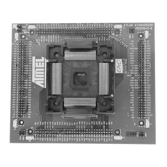
Figure 6-2 & Figure 6-3 show the compatible daughterboards (only one included in the kit). To connect a daughterboard to the motherboard, fit the daughterboard on top of the motherboard by aligning the two arrows together. The two boards will only fit one way. AT40KEL-DK Design Kit 6-25 4334C–AERO–09/06... - Page 28 Board Configuration Figure 6-2. Daughterboard Layout - MQFP160 Figure 6-3. Daughterboard Layout - MQFP256 6-26 AT40KEL-DK Design Kit User Guide 4334C–AERO–09/06...
-
Page 29: Power Configuration
They are located in the bottom left corner. Table 3 lists the switch combinations and Program/Boot their effects. SW4 controls the SER_EN signal line of the motherboard to the 2:1 multi- Settings plexer (device U3) and the AT17 (device U1). SW5 connects signal D0 from the FPGA AT40KEL-DK Design Kit User Guide 6-27 4334C–AERO–09/06... -
Page 30: Programming The At17 Configuration Memory Device
2. Check that the motherboard power switch SW1 is ON and the power configura- tion switches SW2 and SW3 are correct. 3. Make sure programming configuration switches SW4 and SW5 are correct. 4. Verify that the daughterboard is inserted correctly and that it receives power. 6-28 AT40KEL-DK Design Kit User Guide 4334C–AERO–09/06... -
Page 31: In-System Programming At17Lv010 Configuration Eeprom
Make sure to use the latest CPS software (http://www.atmel.com/dyn/prod- ucts/tools_card.asp?tool_id=3191). CPS is used to program configurators and supports Support the ISP cable. The software, in conjunction with Atmel ISP cable, can be used to down- load programming files directly to Atmel’s configurator(s). CPS – Configurator Programming System GUI Based Interface ®... -
Page 32: Connecting Cable To Target System
The control signals generated by the software are fed to the header. The programming algorithms written by Atmel can be used to program an AT17 device in-system. Figure 7-2. In-System Programming Application... -
Page 33: Isp Hardware Interface
Figure 7.4. Figure 7-4. In-System Programming of AT17LV010 for AT40KEL 4.7 kOhm 4.7 kOhm DATA SCLK AT40KEL Device AT17LV010-10DP Device SER_EN RESET DATA0 RESET DATA SER_EN CCLK INIT READY RESET/OE AT40KEL-DK Design Kit User Guide 7-31 4334C–AERO–09/06... - Page 34 DATA DATA CEO(A2) RESET/OE RESET/OE CEO(A2) READY SER_EN READY SER_EN Table 5. 2 Devices Device Device #1 pull down Device #2 pull up Note: No additional logic required, SW1 and SW2 not used. 7-32 AT40KEL-DK Design Kit User Guide 4334C–AERO–09/06...
- Page 35 Device #7 pull up Device #8 pull up Note: SW1, SW2 and some additional logic required for selecting up to 8 devices. Related Documents AT17LV010-10DP Datasheet Programming Specification for Atmel’s FPGA Serial Configuration Memories AT40KEL-DK Design Kit User Guide 7-33 4334C–AERO–09/06...
- Page 36 Section 8 Appendix A AT40KEL-DK Design Kit 8-35 4334C–AERO–09/06...
-
Page 37: Atdh40M Layout Schematics
Appendix A ATDH40M Layout Schematics 8.1.1 Configurator/Multiplexing /Buses 8-36 AT40KEL-DK Design Kit User Guide 4334C–AERO–09/06... -
Page 38: Buses
Appendix A 8.1.2 Buses AT40KEL-DK Design Kit User Guide 8-37 4334C–AERO–09/06... -
Page 39: Power Supply
Appendix A 8.1.3 Power Supply 8-38 AT40KEL-DK Design Kit User Guide 4334C–AERO–09/06... -
Page 40: Atdh2225 Schematics
Appendix A ATDH2225 Schematics AT40KEL-DK Design Kit User Guide 8-39 4334C–AERO–09/06... - Page 41 Disclaimer: The information in this document is provided in connection with Atmel products. No license, express or implied, by estoppel or otherwise, to any intellectual property right is granted by this document or in connection with the sale of Atmel products. EXCEPT AS SET FORTH IN ATMEL’S TERMS AND CONDI- TIONS OF SALE LOCATED ON ATMEL’S WEB SITE, ATMEL ASSUMES NO LIABILITY WHATSOEVER AND DISCLAIMS ANY EXPRESS, IMPLIED OR STATUTORY...
Need help?
Do you have a question about the AT40KEL-DK and is the answer not in the manual?
Questions and answers