
Subscribe to Our Youtube Channel
Related Manuals for Atmel AT73C246-EK1


Summary of Contents for Atmel AT73C246-EK1
- Page 1 AT73C246-EK1 Evaluation Kit ........................User Guide 11047A–PMAAC–08-Apr-10...
- Page 2 AT73C246-EK1 Evaluation Kit User Guide 11047A–PMAAC–08-Apr-10...
-
Page 3: Table Of Contents
Electrostatic Warning ......................2-1 Requirements........................2-1 PC System Requirements....................2-1 Instructions......................... 2-2 2.4.1 To start the AT73C246-EK1 board (before using the AT73C246-EK1 software) 2-2 2.4.2 To turn off the AT73C246-EK1 evaluation board..........2-2 Block Diagram........................2-3 Power Supply ........................2-4 Communication Interfaces .................... - Page 4 Identification LEDs ......................4-2 Serial Interfaces Header ....................4-3 Section 5 Technical Specifications .....................5-1 AT73C246-EK1 ........................5-1 Section 6 PCB Layout.........................6-1 AT73C246-EK1 ........................6-1 Section 7 Schematics .........................7-1 Section 8 Revision History......................8-1 Revision History ......................... 8-1 AT73C246-EK1 Evaluation Kit User Guide 11047A–PMAAC–08-Apr-10...
-
Page 5: Introduction
Section 1 Introduction Congratulations on your purchase of the AT73C246-EK1. It is designed to give designers a quick start to evaluate the power management and audio capability of the AT73C246 and for prototyping and testing of new designs. Scope This document describes the AT73C246-EK1. This board is designed to allow an easy evaluation of the products using demonstration software. -
Page 6: At73C246-Ek1 Features
AT73C246-EK1 Features The AT73C246-EK1 provides the following features: Small size (only 70 x 70mm) with maximum available features. Input power supply: – External Power Supply on VIn pad (2.5V to 5.5V). On-board audio/analog resources: – 100dB Dynamic Range Stereo Audio DAC - 8 to 96 kHz sampling frequency, –... -
Page 7: Deliverables
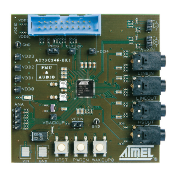
The AT73C246-EK1 package contains the following items: 1. An AT73C246-EK1 board, Figure 1-1. AT73C246-EK1 Top View (card photo) The AT73C246 is located in the center of the AT73C246-EK1 on the Components Side. 2. USB Interface card, AT73C246-EK1 Evaluation Kit User Guide 11047A–PMAAC–08-Apr-10... - Page 8 3. USB cable, 4. 20-pins flat cable, 5. One CD-ROM containing the product’s user guide, full datasheet and ready to use GUI and Com- mand line applications. AT73C246-EK1 Evaluation Kit User Guide 11047A–PMAAC–08-Apr-10...
- Page 9 Figure 1-2. AT73C246-EK1 Components Side AT73C246-EK1 Evaluation Kit User Guide 11047A–PMAAC–08-Apr-10...
- Page 10 AT73C246-EK1 Evaluation Kit User Guide 11047A–PMAAC–08-Apr-10...
-
Page 11: Getting Started
Getting Started Electrostatic Warning The AT73C246-EK1 evaluation board is shipped in protective anti-static packaging. The board must not be subjected to high electrostatic potentials. A grounding strap or similar protective device should be connected when handling the board. Avoid touching the components pins or any metallic element. -
Page 12: Instructions
To start the AT73C246-EK1 board (before using the AT73C246-EK1 software) Install the AT73C246 software by clicking on setup.exe. If the software is downloaded from the Atmel Web site then it is necessary to install first the National Instrument Labview software (LabVIEW8.0.1RuntimeEngine). -
Page 13: Block Diagram
I²S Microcontroller CLK32K RSTB VDD0 0 to 4 BUCK 0 4 Pins Header VDD1 BUCK 1 LDO 2 VDD2 WAKEUP0 VDD3 LDO 3 HRST VDD4 LDO 4 PWREN VBACKUP LDO 5 VDDC LDO 6 AT73C246-EK1 Evaluation Kit User Guide 11047A–PMAAC–08-Apr-10... -
Page 14: Power Supply
Power Supply The AT73C246-EK1 is supplied by an external power supply connected on P1 (positive supply) and P2 (ground). Figure 2-2. Power Supply Diagram AT73C246-EK1 AT73C246 POWER MANAGMENT Min 1A for fully operation BUCK 0 VDD0 VDD1 BUCK 1 AGND... -
Page 15: Communication Interfaces
If using another interface then the USB Communication Box, the VDD3 or VDD0 should be connect on J15 by soldering a 0 ohms resistor on its pads (see VPAD Selection “AT73C246-EK1 Schematic - Power Supply Page” on page 7-5). -
Page 16: Audio Interfaces
Audio Interfaces The AT73C246-EK1 CODEC interface contains various connections of audio elements: Microphones Inputs connected to J5 and J6 (2 pins header for each input). Auxiliary Input connected to J4 (3.5mm jack). Line Input connected to J3 (3.5mm jack). Line Output connected to J2 (3.5mm jack). -
Page 17: Output Voltages
VBACKUP - J10; 2.5V / 10mA (an additional connector J11 is available for rechargeable coin type battery) Figure 2-7. Output Voltages Test-Points (J8, J8, J12, J13, J19) VDD4 VDD3 VDD2 VDD1 VDD0 Figure 2-8. VBACKUP and VCOIN (J10 and J11) VBACKUP VCOIN AT73C246-EK1 Evaluation Kit User Guide 11047A–PMAAC–08-Apr-10... -
Page 18: Input/Output Signals
Figure 2-9. ADC connector (J14) ADC 0 to 3 2.10.2 CLK32K - RTC Output Clock The AT73C246-EK1 provides measuring the internal oscillator frequency (J7). Figure 2-10. CLK32K (J7) RTC Output Clock 2.10.3 The programmable output LED pin can be visualize by the on board led (D1). -
Page 19: Wakeup Push Buttons
2.10.4 Wakeup Push Buttons The AT73C246-EK1 provides 3 on board wakeup push buttons for startup/shutdown operations. HRST - Pressing it for 1 second reset the AT73C246 (when the AT73C246 in “ON”). PWREN - Pressing it for 5 sec start/stop the AT73C246. - Page 20 2-10 AT73C246-EK1 Evaluation Kit User Guide 11047A–PMAAC–08-Apr-10...
-
Page 21: At73C246-Ek1 Software Interface
Operation selection 3.1.2 Login Errors USB Communication Issue In software startup - In case of “Communication Issue” check USB cable connectivity and/or COM selection. Then, select Retry or Exit. Figure 3-2. Communication Error AT73C246-EK1 Evaluation Kit User Guide 11047A–PMAAC–08-Apr-10... - Page 22 USB Connection Issue While software runs - In case of “Connection Issue” check USB cable connectivity. Then, select Retry or Exit. Figure 3-3. Connection Issue AT73C246-EK1 Evaluation Kit User Guide 11047A–PMAAC–08-Apr-10...
-
Page 23: Functionality And Control Pages
Serial port OK Product “OFF” Serial port OK Product “ON” Serial port not connected Product off (no connection) Read Registers Audio Initialisation Command (Demonstration example) Registers Table ADC Sampling Period ADC Function Sampling Elements AT73C246-EK1 Evaluation Kit User Guide 11047A–PMAAC–08-Apr-10... - Page 24 Software Panel - Audio Configuration Path Select Codec Codec Standby On/Off Codec Configuration I²S Configuration Figure 3-6. Software Panel - Audio Input-Output Audio Input Control Audio Output Control Audio Input Headphone Plug Mixer In-Out Detector AT73C246-EK1 Evaluation Kit User Guide 11047A–PMAAC–08-Apr-10...
- Page 25 Software Panel - Audio Effect & Microphone Mono ADC/DAC Control Control 3D Effect Microphone Control De-emphasis Filter Headphone Tone Control Figure 3-8. Software Panel - Audio Volume Path Mute Microphone Sidetone Line Headphone Volume Gain Volume AT73C246-EK1 Evaluation Kit User Guide 11047A–PMAAC–08-Apr-10...
- Page 26 Control VDD2 Working Mode Control On/Off Command VDD0 Control VDD1 Control Led Control Figure 3-10. Software Panel - Register Mapping Read Write Data Data Register Command Command Write Read Address Registers Access Registers Table AT73C246-EK1 Evaluation Kit User Guide 11047A–PMAAC–08-Apr-10...
-
Page 27: Usb-To-Serial Card
Avoid touching the components pins or any metallic element. Requirements In order to set up the USB-to-Serial Card the following items are needed: 1. The USB-to-Serial Card itself. 2. PC station with a standard USB connector. 3. The 20-leads flat cable. AT73C246-EK1 Evaluation Kit User Guide 11047A–PMAAC–08-Apr-10... -
Page 28: Instructions
Figure 4-2. GPIO Side Pin N°19 Pin N°1 Pin N°20 Pin N°2 Identification LEDs The bi color LED indentify the following statuses: – Continuous Green - Power “ON” – Blinking Red - Data transmitting AT73C246-EK1 Evaluation Kit User Guide 11047A–PMAAC–08-Apr-10... -
Page 29: Serial Interfaces Header
5. 12.288 MHz Clock - The USB-to-Serial Card’s oscillator provides a 12.288MHz clock (+3.3V p-p via pin 12). This clock is necessary for driving the digital core of the evalu- ated board. AT73C246-EK1 Evaluation Kit User Guide 11047A–PMAAC–08-Apr-10... - Page 30 AT73C246-EK1 Evaluation Kit User Guide 11047A–PMAAC–08-Apr-10...
- Page 31 – Physical Dimensions.................... L= 70 x W=70 x H=20 mm – Weight.................................70 g Operating Conditions – External Voltage Supply (on Vin Pad)................... 2.9V - 5.5V Connections – Communication Connector (for I²S and TWI)..............2x10 pins Header AT73C246-EK1 Evaluation Kit User Guide 11047A–PMAAC–08-Apr-10...
- Page 32 AT73C246-EK1 Evaluation Kit User Guide 11047A–PMAAC–08-Apr-10...
-
Page 33: Pcb Layout
Section 6 PCB Layout AT73C246-EK1 Figure 6-1. Layer 1 - Components Layer Note: Size not to scale AT73C246-EK1 Evaluation Kit User Guide 11047A–PMAAC–08-Apr-10... - Page 34 Figure 6-2. Layer 2 Note: Size not to scale AT73C246-EK1 Evaluation Kit User Guide 11047A–PMAAC–08-Apr-10...
- Page 35 Figure 6-3. Layer 3 Note: Size not to scale AT73C246-EK1 Evaluation Kit User Guide 11047A–PMAAC–08-Apr-10...
- Page 36 Figure 6-4. Layer 4 - Print Side Note: Size not to scale AT73C246-EK1 Evaluation Kit User Guide 11047A–PMAAC–08-Apr-10...
- Page 37 Figure 6-5. Silk Screen AT73C246-EK1 Evaluation Kit User Guide 11047A–PMAAC–08-Apr-10...
- Page 38 AT73C246-EK1 Evaluation Kit User Guide 11047A–PMAAC–08-Apr-10...
- Page 39 Section 7 Schematics Figure 7-1. AT73C246-EK1 Schematic - Main Page AT73C246-EK1 Evaluation Kit User Guide 11047A–PMAAC–08-Apr-10...
- Page 40 Figure 7-2. AT73C246-EK1 Schematic - AT73C246 Page AT73C246-EK1 Evaluation Kit User Guide 11047A–PMAAC–08-Apr-10...
- Page 41 Figure 7-3. AT73C246-EK1 Schematic - Audio Interface Page AT73C246-EK1 Evaluation Kit User Guide 11047A–PMAAC–08-Apr-10...
- Page 42 Figure 7-4. AT73C246-EK1 Schematic - Digital Interface Page AT73C246-EK1 Evaluation Kit User Guide 11047A–PMAAC–08-Apr-10...
- Page 43 Figure 7-5. AT73C246-EK1 Schematic - Power Supply Page AT73C246-EK1 Evaluation Kit User Guide 11047A–PMAAC–08-Apr-10...
- Page 44 AT73C246-EK1 Evaluation Kit User Guide 11047A–PMAAC–08-Apr-10...
-
Page 45: Revision History
Section 8 Revision History Revision History Table 8-1. Revision History Change Request Doc. Rev Date Comments Ref. 11047A 08-Apr-10 AT73C246-EK1 Evaluation Kit User Guide 11047A–PMAAC–08-Apr-10... - Page 46 AT73C246-EK1 Evaluation Kit User Guide 11047A–PMAAC–08-Apr-10...
- Page 47 Disclaimer: The information in this document is provided in connection with Atmel products. No license, express or implied, by estoppel or otherwise, to any intellectual property right is granted by this document or in connection with the sale of Atmel products. EXCEPT AS SET FORTH IN ATMEL’S TERMS AND CONDI- TIONS OF SALE LOCATED ON ATMEL’S WEB SITE, ATMEL ASSUMES NO LIABILITY WHATSOEVER AND DISCLAIMS ANY EXPRESS, IMPLIED OR STATUTORY...
- Page 48 AT73C246-EK1 Evaluation Kit User Guide 11047A–PMAAC–08-Apr-10...
Need help?
Do you have a question about the AT73C246-EK1 and is the answer not in the manual?
Questions and answers