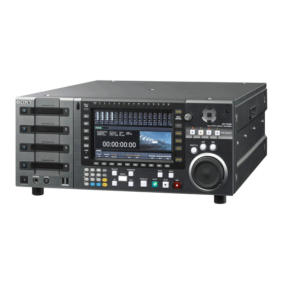
Sony SRR1000 Operation Manual
Memory storage unit
Hide thumbs
Also See for SRR1000:
- Brochure (17 pages) ,
- Operation manual (93 pages) ,
- Installation manual (42 pages)
Table of Contents
Advertisement
Quick Links
Advertisement
Table of Contents

Related Manuals for Sony SRR1000


Summary of Contents for Sony SRR1000
- Page 1 MEMORY STORAGE UNIT SR-R1000 OPERATION MANUAL [English] 1st Edition...
-
Page 2: Important Safety Instructions
THIS APPARATUS MUST BE EARTHED. Before operating the unit, please read this manual thoroughly and retain it for future reference. CAUTION Danger of explosion if battery is incorrectly replaced. Important Safety Instructions Replace only with the same or equivalent type recommended by the manufacturer. - Page 3 In order to use this product safely, avoid prolonged For the customers in Europe listening at excessive sound pressure levels. The manufacturer of this product is Sony Corporation, 1- 7-1 Konan, Minato-ku, Tokyo, Japan. WARNING The Authorized Representative for EMC and product...
- Page 4 à l’interrupteur principal. contrôlé, ex. studio de télévision). Pour mettre l’appareil complètement hors tension, éteignez l’interrupteur électrique principal sur le panneau Pour les clients en Europe arrière. Le fabricant de ce produit est Sony Corporation, 1-7-1 Konan, Minato-ku, Tokyo, Japon.
- Page 5 VORSICHT Le représentant autorisé pour EMC et la sécurité des produits est Sony Deutschland GmbH, Hedelfinger Strasse Explosionsgefahr bei Verwendung falscher Batterien. 61, 70327 Stuttgart, Allemagne. Pour toute question Batterien nur durch den vom Hersteller empfohlenen oder concernant le service ou la garantie, veuillez consulter les einen gleichwertigen Typ ersetzen.
- Page 6 (Störfestigkeit) Für die folgende elektromagnetische Umgebung: E4 (kontrollierter EMV-Bereich, z.B. Fernsehstudio). Für Kunden in Europa Der Hersteller dieses Produkts ist Sony Corporation, 1-7-1 Konan, Minato-ku, Tokyo, Japan. Der autorisierte Repräsentant für EMV und Produktsicherheit ist Sony Deutschland GmbH, Hedelfinger Strasse 61, 70327 Stuttgart, Deutschland. Bei...
-
Page 7: Table Of Contents
Table of Contents Chapter 1 Overview Features..................10 High-Quality Recording ..............10 Multiple Ports ..................10 Multiple Resolutions................10 Large Storage Capacity................ 10 Other Features..................11 Chapter 2 Names and Functions of Parts Control Panel ................. 12 Connector Panel ................17 Display Screen................ - Page 8 Chapter 4 Basic Operations Selecting Input/Output Ports and SRMemory Slots ....32 Recording ..................33 Playback ..................34 Chasing Playback ................34 Variable Speed Playback..............34 Still Picture Output ................36 File Operations................36 Selecting Audio Signals..............38 Selecting the Audio Input Signals ............38 Selecting the Audio Signals to Monitor ..........
- Page 9 Index ....................67 Table of Contents...
-
Page 10: Chapter 1 Overview
With the ability to simultaneously record and play back applications. video from four input/output ports, the unit offers high SRMASTER and SRMemory are trademarks of Sony efficiency in video production. Corporation. You can also select which of the video ports and SRMemory cards you want to use, and access a single memory card from multiple ports simultaneously. -
Page 11: Other Features
• FTP protocol is supported for video data transfer in MXF format via a network. • Equipped with two network ports that support Gigabit Ethernet. • Compatible with Sony VTR protocol and Sony Disk protocol, and switcher and controller operations are supported. Features... -
Page 12: Chapter 2 Names And Functions Of Parts
Names and Functions of Parts Chapter Control Panel The control panel consists of the following sections: A SRMemory slot section B Menu control section C Port control section (see page 13) (see page 14) (see page 15) G Search control section (see page 16) F Recording/playback control section (see page 15) E Editing control section (see page 15) D Numeric buttons (see page 15) -
Page 13: Srmemory Slot
A SRMemory slot section 1) Flashing LED: Flashes at 1-second interval. Fast flashing LED: Flashes at 1/4-second interval. For details on salvage operations and formatting when problems have occurred, see “Troubleshooting” in the Appendix (page 56). c SRMemory slot Insert an SRMemory card. d On/Standby button and indicator Switches the unit between on and standby when the main power switch on the connector panel is turned on. - Page 14 B Menu control section a DISPLAY button h DIAG (diagnostic) button Displays the video signal on the entire display. Displays the DIAG menu when pressed together with the SFT button. b CH (channel) selection buttons i MEM button Select the channel to adjust the audio recording/playback level or to select an audio input.
-
Page 15: Next Button
C Port control section E Editing control section Currently cannot be used. F Recording/playback control section a Cursor buttons Move the cursor (shown in reverse video) on the display. Also used to change settings values. b PORT SELECT buttons/indicators (page 32) Buttons: Select the input/output port to use. -
Page 16: Shuttle Button
G Search control section a SHUTTLE button Press to enter shuttle mode. In this mode, the button is lit and playback at the speed corresponding to the position of the search dial is possible (–100 to +100 times normal playback speed). The search dial clicks at the positions for still pictures and ±10 times normal playback speed. -
Page 17: Connector Panel
Connector Panel A Input/output ports (see page 17) Port A Port B Port C Port D B Remote input/output C Analog output/power supply * At the time of shipment from the factory, no boards are connected to ports A to C. section (see page 18) section (see page 19) An output board is connected to port D. - Page 18 HTTP, transferring 9-pin connector. files via FTP, etc. The Sony 9-pin VTR protocol and Sony 9-pin Disk protocol are supported. CAUTION • For safety, do not connect the connector for peripheral...
- Page 19 C Analog output/power supply section a AUDIO MONITOR OUTPUT connectors Output the audio monitor signals. b Main power switch Turns on/off the main power supply. When the main power is turned on, the On/Standby indicator on the control panel lights. Normally, this switch should be left in the top (on) position during operation, and standby status switching should be performed using the On/Standby button on the control...
-
Page 20: Display Screen
Display Screen The color display of the unit is capable of displaying a four-port display screen that shows all of the four ports and a one-port display screen that shows only the selected port. When the screen is four-port display, pressing the PORT SELECT button of the selected port switches to one-port display. - Page 21 One-port display b Audio level meters APort information display section (see page 21) BStatus bar (see page 22) a Menu display section a Menu display section (page 41) b Audio level meters Displays a menu. Displays the audio recording/playback levels. The meters are only displayed in the one-port display screen.
-
Page 22: Status Bar
One-port display n Time code (Second area) a Port name m Time code Indicates the time code based on the setting of the TC b SRMemory slot name menu. c File name n Time code (Second area) Indicates the time code when the ALT/[F5] (TC2 SEL) d Video format buttons are set to anything other than Off in the TC menu. -
Page 23: File List Screen
e Network access f Remote control Indicates the number of the slot with the SRMemory card Indicates the input/output port manipulated by a remote which is being accessed from network. controller. File List Screen Press the memory selection buttons to display the list of files in the SRMemory card inserted. -
Page 24: Chapter 3 Setting Up The Memory Storage Unit
Setting Up the Memory Storage Unit Chapter Connecting External HD digital recorder Devices This section describes how to connect the unit to external devices to record or play back data. In the explanations in this section, input boards are connected to ports A and C, and output boards to ports B and D. -
Page 25: Reference Signals
Reference Signals This section describes how the reference signals for video output are selected. Reference Signals for Output Video Signals The output video signals of the unit are synchronized and output as follows depending on the unit’s operation state, settings, and input signals. Start Input What is the setting of the... -
Page 26: Reference Signal Connections
For playback Reference Signal Connections Reference signal Connect reference signals as follows, according to your recording or playback requirements. Reference signal connections For recording signals from a switcher or signal generator Reference signal 75 Ω terminal switch: ON Switcher or signal generator HD serial input monitor Note... -
Page 27: Time Code Settings
Setting the Time Code Generator Time Code Settings There are two ways to record time codes with the unit. One way is to record the output of the unit’s internal time code generator. The other is to directly record time codes that Selecting the Time Data are input from an external time code generator. - Page 28 Notes • The values read by the time code reader cannot be reset. • Time data cannot be reset when the internal time code generator is locked to external time codes or to values read by the time code reader. To set the user bits Use the [F5] (TM SEL) button in the TC menu to select “UB”.
-
Page 29: Superimposing Character Information
b Drop frame mark of the time code reader Superimposing Character “.”: Drop frame mode “:”: Non-drop frame mode Information c Drop frame mark of the time code generator “.”: Drop frame mode “:”: Non-drop frame mode To superimpose characters representing the time data, operation mode, and other information on output signals, d Field mark of the VITC data set the ALT/[F10] (CHAR ON) buttons to On in the TC... -
Page 30: Handling Srmemory Cards
For details on error messages, see “Error Messages” Handling SRMemory (page 58). For details on warning messages, see “Warning Messages” (page 60). Cards When error messages and warning messages occur simultaneously, the number of error message occurrences flashes twice, and then the number of warning message Recommended SRMemory Cards occurrences flashes twice. -
Page 31: Preventing Accidental Data Loss
Inserting SRMemory cards Set the On/Standby switch to On. Insert the SRMemory card in any of the SRMemory slots 1 to 4. When the SRMemory card is inserted, the mount process is performed automatically. Ejecting SRMemory cards Press the corresponding eject button. The file close and unmount processes are performed, and the SRMemory card is ejected automatically. -
Page 32: Chapter 4 Basic Operations
Basic Operations Chapter Perform a recording or playback operation. Selecting Input/Output When recording to an SRMemory card from an input port Ports and SRMemory and when playing back data from an SRMemory card to an output port, select the port first and then the SRMemory Slots slot. -
Page 33: Recording
already being used for recording in step 3 of the procedure Recording above. Note This section describes the example of recording input When multiple SRMemory cards, input and output ports signals from port A to the SRMemory card in slot M1. are used to record or play back files simultaneously, some functions are limited depending on the SRMemory card type used or the port configuration. -
Page 34: Playback
Chasing Playback Playback A file being recorded to an SRMemory card can be played back without waiting for recording to end. This section describes the example of playing back a file in This section describes the example of recording signals the SRMemory card inserted in slot M2 on a device from port A to slot M1 and playing back the same file connected to port B. - Page 35 Jog mode playback Shuttle mode Follow the procedure below to play back in jog mode. The data is played back at a speed that corresponds to the position of the search dial. The dial clicks at the positions for –10, 0, and +10 times normal playback speed.
-
Page 36: Still Picture Output
Return the search dial to the center position or press File Operations the STOP button to stop variable mode playback. To return to normal-speed playback Press the PLAY button. Files recorded to SRMemory cards can be operated on the To alternate between normal-speed playback and unit. - Page 37 Use the cursor buttons or MULTI CONTROL knob to Button Indication Description select the file. ALT/[F3] SET FLAG Sets any of the following flags for the selected files. You can also select multiple files. Press the ALT/[F2] (FILE LOCK) buttons. KEEP None The selected file is locked.
-
Page 38: Selecting Audio Signals
Selecting Audio Signals This section describes how to select the audio signals to input or monitor before you start recording or playback. Selecting the Audio Input Signals Make the settings as follows in accordance with the audio input signals. Press the PORT SELECT button of the input port you want to set once or twice to display the one-port display screen on the color display. -
Page 39: Adjusting The Audio Levels
To adjust the recording level manually Adjusting the Audio Press the AUDIO button while the one-port display screen is displayed to enter level adjustment mode. Then, make Levels the channel you want to adjust manually active, and use the cursor buttons or MULTI CONTROL knob to adjust the level so that the audio level meter indicates a level that is close to the reference –20 dB when at the average volume This section describes how to adjust the audio level for... -
Page 40: Adjusting The Output Video Signal
Adjusting the setup level Adjusting the Output Use the [F5] (SETUP) button in the VIDEO menu to set the level. Video Signal prst: 0% (0) Numerical value: –10.0% to +10.0% Adjustable range: –10% to +10% Setting procedure Set the output video signal menu items as follows. Adjusting the black output level Use the [F6] (BLK LV) button in the VIDEO menu to set Press a function selection button (e.g.: [F1]). -
Page 41: Chapter 5 Menu Items
Menu Items Chapter This unit has the following menus to enable a number of Press the VIDEO button. settings. The VIDEO menu screen appears. HOME menu: Sets the basic operation modes for recording and playback. TC menu: Makes time code settings. VIDEO menu: Adjusts video signals. -
Page 42: Saving Settings
Press the [F2] (SCAN) button to change the setting. Saving Settings Each press of the button changes the setting. The menu items include settings for the overall unit and You can store up to 8 sets of unit settings in the user banks settings for each port. -
Page 43: Detailed Menu Description
Detailed Menu Description HOME Menu The HOME menu allows you to set the basic operation The Target column displays the following data. modes for recording and playback. Unit: Settings for the overall unit In: Settings for the input ports Settings in the Setting column are the values that appear in Out: Settings for the output ports the menu display section of the screen. -
Page 44: Tc Menu
TC Menu The TC menu allows you to set all of the items related to time codes from a single menu. Button Indication Setting Target [F1] TCG SRC Selects whether to synchronize the internal time code generator with the external signal. - Page 45 Button Indication Setting Target ALT/[F5] TC2 SEL Sets whether to use two lines for the time code display section and selects the time code type for 2nd line when the screen is one-port display. For input ports: For output ports: VITC ALT/[F7] CHAR SET...
-
Page 46: Video Menu
VIDEO Menu The VIDEO menu allows you to adjust video signals. Button Indication Setting Target [F1] MASTER Simultaneously adjusts the Y, PB, and PR levels of the HD video signal output via the SD/HD SDI OUT connectors. (see page 40) 0.0 to 100% (4000H) to 141.3% (5A70H) [F2] Adjusts the Y level of the HD video signal output via the SD/HD SDI OUT... - Page 47 Button Indication Setting Target ALT/[F8] MONITOR Sets the settings for monitor output in 3D mode. SETTING [F1] DUAL Sets the monitor output for 3D mode. Link-AB: Outputs each of the LINK-A signal (the signal input from the HD SDI INPUT A connector) and LINK-B signal (the signal input from the HD SDI INPUT B connector) in the same way as with main output.
-
Page 48: Audio Menu
Button Indication Setting Target [F6] Sets the format of SDI signals. HDSDI 3GSDI [F7] DEPTH Sets the bit length of input/output signals. 10bit (fixed) [F8] COMPRS Sets the compression mode. SR-SQ SR-Lite [F9] Applies the settings. [F10] EXIT Redisplays the previous menu. –... -
Page 49: Setup Menu
Button Indication Setting Target ALT/[F5] A/E IN Selects whether to pass the signals input to the DIGITAL AUDIO INPUT (AES/EBU) connector through the sampling rate converter. Auto: Passes the input signals through the sampling rate converter. In this case, there are no limitations on input signals. Vlock: Does not pass the input signals through the sampling rate converter. - Page 50 Button Indication Setting Target [F3] ENABLE Sets the buttons that can be operated on the control panel when the unit is used in Unit remote control mode. Disable: Disables all switches and buttons. Enable: Enables all switches and buttons. Stp&Ejct (Stop&Eject): Enables only the STOP and Eject buttons. Lcl map (Local Key Map): Enables the buttons set to Enable in [F4] (MAP).
-
Page 51: Appendix
Appendix Set the IP address and other network setting items for FTP File Operations this unit. For details, see the Installation Manual. To connect a computer running Windows Vista or File operations between this unit and a remote computer Windows 7 can be carried out by the File Transfer Protocol (called Disable the Internet Protocol Version 6 (TCP/IPv6). -
Page 52: Command List
Refer to the Windows help for more information about PASS the FTP command. Verifies the password. If the connection succeeds, you are prompted to enter Command syntax: PASS <SP> <password> <CRLF> a user name. Input example: PASS sr-r1000 Enter the user name “usr1” and press the Enter key. QUIT Terminates the FTP connection. - Page 53 Command syntax: STRU <SP> <structure-code> RNFR <CRLF> RNTO Rename a file. <structure-code> can be any of the following. However, Specify the file to be renamed with the RNFR command, for the unit, the structure is always “F”, regardless of the and specify the new name with the RNTO command.
- Page 54 - Serial number CDUP - Protection information Moves one level up in the directory structure (makes the - Volume label parent of the current directory be the current directory). - Date access started Command syntax: CDUP <CRLF> - Last format date - Last update date - Remaining capacity (GB) Extended commands...
-
Page 55: Restrictions
When both S25/S15 and S55 cards are Restrictions used Using S25 or S15 cards for recording Restrictions on Simultaneous S25 or S15 Recording and Playback With this unit, you can record the signals simultaneously from multiple input ports in separate files on one Port A SRMemory card and play back the files in the SRMemory Port B... -
Page 56: Troubleshooting
Playback only Troubleshooting S25 or S15 Salvaging SRMemory Card in the Event Recording does not End Port A (Output) Normally Port B (Output) Port C (Output) After recording is completed, press the Eject button to Port D (Output) safely eject the SRMemory card, or press the On/Standby button on the front panel to end unit operation. - Page 57 Using salvage to restore files Notes • If the ALT/[F9] (REC INHI) buttons in the HOME Insert the SRMemory card for which recording did not menu are set to anything other than Off, change it to end normally into a slot. Off.
-
Page 58: Error Messages
After an error message is displayed, eliminate the cause of the error based on the error message and then turn the unit back on. If the error message appears again when the unit is turned on, contact your Sony representative. Code Indication... - Page 59 Code Indication Meaning D5xxss SLOT Mx INTERFACE ERROR1, etc. An error occurred when communicating with the SRMemory card in the indicated slot. This SRMemory card cannot be used in its present state. Remove the SRMemory card and insert it again. If the error persists, the unit or the SRMemory card may be damaged.
-
Page 60: Warning Messages
Warning Messages Warning message When one of the problems described below is detected by the unit, a warning mark and message appear on the status bar. Operation can continue even when the warning mark appears. When multiple errors occur simultaneously, the number of errors is indicated to the right of the warning mark. - Page 61 Code Indication Meaning 1F01pp PORT x NO A13/A14 INPUT No carrier detected on digital audio input on channel 13/ (P-x NO A13/A14) channel 14 for the indicated port. 2001pp PORT x NO A15/A16 INPUT No carrier detected on digital audio input on channel 15/ (P-x NO A15/A16) channel 16 for the indicated port.
- Page 62 Code Indication Meaning E201ss SLOT Mx NEAR END The remaining recording time is less than 5 minutes on the (Mx NEAR END) SRMemory card in the indicated slot. E202pp PORT x FULL, STOP RECORDING The SRMemory card in the indicated port is full and (P-x FULL STOP) recording was terminated.
- Page 63 SRMemory Status Messages The following warning messages appear depending on the of the following messages appear, it is time to replace an wear or usage of the SRMemory card. Using repeatedly an SRMemory card with a new one. If the “CONDITION x SRMemory card gradually increases the possibility that BAD”...
-
Page 64: Specifications
Video Specifications 422 format Sampling frequency Y: 74.25 MHz, General Pb/Pr: 37.125 MHz Quantization 10 bits Recording format MPEG4 SStP format Compression MPEG4 SStP Power requirements 444 format 100 V to 240 V AC Sampling frequency Power consumption RGB: 74.25 MHz Maximum 480 W Quantization 10 bits... - Page 65 • Always make a test recording, and verify that it was BTA-S004B standard) recorded successfully. TIMECODE OUTPUT SONY WILL NOT BE LIABLE FOR DAMAGES OF BNC (1) ANY KIND INCLUDING, BUT NOT LIMITED TO, 2.2 Vp-p, low impedance COMPENSATION OR REIMBURSEMENT ON...
-
Page 66: Mpeg-4 Visual Patent Portfolio License
MPEG-4 Visual Patent Portfolio License THIS PRODUCT IS LICENSED UNDER THE MPEG-4 VISUAL PATENT PORTFOLIO LICENSE FOR THE PERSONAL AND NON-COMMERCIAL USE OF A CONSUMER FOR (i) ENCODING VIDEO IN COMPLIANCE WITH THE MPEG-4 VISUAL STANDARD (“MPEG-4 VIDEO”) AND/OR (ii) DECODING MPEG-4 VIDEO THAT WAS ENCODED BY A CONSUMER ENGAGED IN A PERSONAL AND NON-COMMERCIAL ACTIVITY AND/OR WAS OBTAINED FROM A... - Page 67 Disable audio signal 48 Main screen 20 Index DISPLAY button 14 MAINTENANCE connector 18 Display range 48 Maintenance information display 60 Drop frame mode 44 MEM button 14 Memory selection button 14 Symbols Menu 41 +/– button 15 AUDIO 48 Eject button 13 file list 36 Error message 58...
- Page 68 User bank 42 User bit 28 Salvaging 56 Sampling rate 47 Saving setting 42 Scanning method 47 VAR button 16 Screen 20 Variable mode playback 35 SD/HD SDI MONITOR A/B/MULTI Variable speed playback 34 connector 18 VIDEO CONTROL connector 18 SD/HD SDI OUT A/B connector 18 VIDEO menu 46 SDI signals 48...
- Page 69 The material contained in this manual consists of information that is the property of Sony Corporation and is intended solely for use by the purchasers of the equipment described in this manual. Sony Corporation expressly prohibits the duplication of any...
- Page 70 Sony Corporation SR-R1000 (SY) 4-285-471-01 (1) © 2011...
Need help?
Do you have a question about the SRR1000 and is the answer not in the manual?
Questions and answers