HP ProCurve 2610 Installation And Getting Started Manual
Hide thumbs
Also See for ProCurve 2610:
- User manual (68 pages) ,
- Selection manual (2 pages) ,
- Advanced traffic management manual (364 pages)
Table of Contents
Advertisement
Advertisement
Table of Contents
Troubleshooting

Subscribe to Our Youtube Channel
Related Manuals for HP ProCurve 2610


Summary of Contents for HP ProCurve 2610
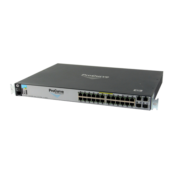
- Page 1 ProCurve 2610 Switches Installation and Getting Started Guide Power over Ethernet...
- Page 3 HP ProCurve 2610 Switches Installation and Getting Started Guide...
- Page 4 Applicable Products accompanying such products and services. Nothing herein should be construed as constituting an additional warranty. HP shall not be liable for technical or editorial errors or omissions contained herein. HP ProCurve Switch 2610-24 (J9085A)
-
Page 5: Table Of Contents
Contents 1 Introducing the Switch Front of the Switch ..........1-4 Network Ports . - Page 6 6. Installing or Removing mini-GBICs ......2-17 Installing the mini-GBICs: ....... . 2-17 Removing the mini-GBICs .
- Page 7 Downloading New Switch Software ......4-13 HP Customer Support Services ........4-13 Before Calling Support .
- Page 8 B Cabling and Technology Information Cabling specifications ........B-1 Technology distance specifications .
- Page 9 D Recycle Statements Waste Electrical and Electronic Equipment (WEEE) Statements ..D-1 Index...
-
Page 11: Introducing The Switch
Introducing the Switch The ProCurve 2610 Switches are multiport switches that can be used to build high-performance switched workgroup networks. These switches are store- and-forward devices that offer low latency for high-speed networking. The 2610-PWR Switches also support Redundant Power Supply and Power over Ethernet (PoE) technologies. - Page 12 Fiber (single mode) 1000-BX Fiber (single mode) For supported transceivers, see www.hp.com/go/procurve/faqs. ProCurve Mini- GBICs and SFPs have links to a list of supported products (first question in the “General product information” category). For technical details of cabling and technologies see “Cabling and Technology Information”...
- Page 13 Introducing the Switch ■ For further information regarding PoE power, see the PoE Planning and Implementation Guide, which is on the ProCurve Web site at www.hp.com/go/procurve/manuals, (See page 1-13). Redundant and External Power Supply Support - The 2610-PWR ■ Switches can be connected to a ProCurve 600 Redundant and External...
-
Page 14: Front Of The Switch
Introducing the Switch Front of the Switch Front of the Switch Power RPS, Fan and Test ProCurve Switch 2610-48 Switch port LEDs and Fault Status LEDs LEDs LED Mode select button Uplink ports Console Reset and Clear 10/100Base-TX RJ-45 ports and indicator LEDs (1000Base-T and mini-GBIC) -
Page 15: Network Ports
Introducing the Switch Front of the Switch Network Ports ■ 24, or 48 auto-sensing 10/100Base-TX ports. All these ports have the “Auto-MDIX” feature, which means that you can use either straight-through or crossover twisted-pair cables to connect any network devices to the switch. Two RJ-45 10/100/1000Base-T ports for high speed uplink. - Page 16 Introducing the Switch Front of the Switch Switch LEDs State Meaning Normal operation. The switch is ready to supply PoE power (green/ orange) Flashing/ One or more ports has experienced a fault condition for PoE delivery. The orange Fault LED will be flashing simultaneously. If it is a self test failure, the Test LED will be flashing simultaneously.
- Page 17 Introducing the Switch Front of the Switch Switch LEDs State Meaning Test The normal operational state; the switch is not undergoing self test. (green/ The switch self test and initialization are in progress after the switch has orange) been power cycled or reset. The switch is not operational until this LED goes off.
-
Page 18: Port Leds
Introducing the Switch Front of the Switch Port LEDs The port LEDs provide information about the individual switch ports. Table 1-3. Port LEDs Switch LEDs State Meaning Switch 2610 non-PWR Series Port LEDs Displays port link information, network activity information, whether the port is configured for full-duplex operation, or the speed of the connection depending on the LED Mode selected. -
Page 19: Led Mode Select Button And Indicator Leds
Introducing the Switch Front of the Switch LED Mode Select Button and Indicator LEDs To optimize the amount of information that can be displayed for each of the switch ports in the limited space available, the 2610 Switches use multiple- display LEDs for each port. -
Page 20: Reset Button
Introducing the Switch Front of the Switch Table 1-4. Multiple-Display Port LEDs Switch LEDs State Meaning All 2610 Switches Port LED View Indicates the Port LEDs are displaying network activity information. Indicates the Port LEDs are lit for ports that are in full-duplex mode. indicator LEDs 3 green LEDs) Indicates the Port LEDs are displaying the connection speed at which each... -
Page 21: Console Port
Introducing the Switch Back of the Switch Console Port This port is used to connect a console to a 2610 Switches by using the RJ-45 to DB9 cable, supplied with the switch. This connection is described under “8. (Optional) Connect a Console to the Switch” on page 26 in chapter 2, “Installing the Switch.”... -
Page 22: Rps And Eps Input Port
However, the use of a cross-over cable may be required. For a current list see the FAQ page for the 2610-PWR Switch, which can be found on the ProCurve Web site, www.hp.com/go/procurve/manuals, Technical Support, FAQs (all). Plug-and-play networking—all ports are enabled—just connect the ■... - Page 23 Support for many advanced features to enhance network performance— for a description, see the Management and Configuration Guide, which is on the ProCurve Web site at www.hp.com/go/procurve/manuals. To display the list of downloadable manuals, click on the following link: HP ProCurve Switch 2610 Series.
-
Page 25: Installing The Switch
Installing the Switch The ProCurve 2610 Switches come with an accessory kit that includes the brackets for mounting the switch in a standard 19-inch telco rack, in an equipment cabinet, or on a wall. The brackets are designed to allow mounting the switch in a variety of locations and orientations. - Page 26 Installing the Switch Included Parts ■ AC power cord, one of the following: Non-PWR Switches PWR Switches Australia/New Zealand 8120-6803 8120-6810 China 8120-8377 8120-8471 Continental Europe 8120-6802 8120-6811 Denmark 8120-6806 8120-6814 Japan 8120-6804 8120-6804 Switzerland 8120-6807 8120-6815 United Kingdom/Hong Kong/Singapore 8120-8709 8120-6809 United States/Canada/Mexico...
-
Page 27: Installation Precautions
Installing the Switch Included Parts Installation Precautions W A R N I N G ■ The rack or cabinet should be adequately secured to prevent it from becoming unstable and/or falling over. Devices installed in a rack or cabinet should be mounted as low as possible, with the heaviest devices at the bottom and progressively lighter devices installed above. -
Page 28: Installation Procedures
Installing the Switch Installation Procedures Installation Procedures These steps summarize your switch installation. The rest of this chapter provides details on these steps. Prepare the installation site (page 2-6). Make sure the physical environment into which you will be installing the switch is properly prepared, including having the correct network cabling ready to connect to the switch and having an appropriate location for the switch. - Page 29 Installing the Switch Installation Procedures (Optional) Connect a console to the switch (page 2-26). You may wish to modify the switch’s configuration, for example, to configure an IP address so it can be managed using a web browser, from an SNMP network management station, or through a Telnet session.
-
Page 30: Prepare The Installation Site
Installing the Switch Installation Procedures 1. Prepare the Installation Site Cabling Infrastructure - Ensure the cabling infrastructure meets the necessary network specifications. See the following table for cable types and lengths, and see appendix B, “Cabling and Technology Information” for more information: ■... - Page 31 Installing the Switch Installation Procedures N o t e The 2610 Switches do not have a power switch. They are powered on when the power cord is connected to the switch and to a power source. For safety, the power outlet should be located near the switch installation. The switch automatically adjusts to any voltage between 100-127 or 200-240 volts and either 50 or 60 Hz.
-
Page 32: Led Behavior
Installing the Switch Installation Procedures When the switch is powered on, it performs its diagnostic self test. Self test takes approximately 50 seconds to complete. Switch port LEDs Self Test LED Power and Fault LEDs Figure 2-3. Checking the LEDs on the 2610-PWR switches LED Behavior During the self test: •... -
Page 33: Mount The Switch
Installing the Switch Installation Procedures 3. Mount the Switch After the switch passes self test, it is ready to be mounted in a stable location. The 2610 Switches can be mounted in these ways: Mounting Location Non-PWR Switches PWR Switches In a rack or cabinet On a horizontal surface On a wall... -
Page 34: Rack Mounting The 2610-Pwr Switches
Installing the Switch Installation Procedures Rack Mounting the 2610-PWR switches Use a #1 Phillips (cross-head) screwdriver and attach the mounting brackets to the switch with the included 8-mm M4 screws. Figure 2-4. Attaching large mounting brackets W A R N I N G For safe reliable installation, only use the screws provided in the accessory kit to attach the mounting brackets to the switch. - Page 35 Installing the Switch Installation Procedures Hold the switch with attached brackets up to the rack and move it vertically until rack holes line up with the bracket holes, then insert and tighten the four number 12-24 screws holding the brackets to the rack. Install 12-24 screws Figure 2-5.
-
Page 36: Rack Mounting The Non-Pwr Switches
Installing the Switch Installation Procedures Rack Mounting the Non-PWR Switches Use a #1 Phillips (cross-head) screwdriver and attach the mounting brackets to the switch with the included 8-mm M4 screws. 8 mm M4 screws Figure 2-6. Attaching small mounting brackets N o t e The mounting brackets have multiple mounting holes and can be rotated allowing for a wide variety of mounting options. - Page 37 Installing the Switch Installation Procedures Hold the switch with attached brackets up to the rack and move it vertically until rack holes line up with the bracket holes, then insert and tighten the four number 12-24 screws holding the brackets to the rack. Install 12-24 screws Figure 2-7.
-
Page 38: Flat Wall Mounting
Installing the Switch Installation Procedures Flat Wall Mounting There are two switches in this series that can be wall mounted, the J9085A 24- port Non-PoE and the J9088A 48-port Non-PoE. You can mount these switches on a wall as shown in the illustration Figure 2-8. Wall mounting is not supported for the 2610-PWR switches because of the size and weight of the devices. -
Page 39: Horizontal Surface Mounting
Installing the Switch Installation Procedures RJ-45 Ports Wall M4 screws 5/8-inch wood screws Figure 2-8. Horizontal wall mounting C a u t i o n The J9088A 48-port, non-PWR switch can be wall mounted with either the RJ-45 ports side up or down in the horizontal orientation. A vertical wall mount orientation is not supported. -
Page 40: Connect The Switch To A Power Source
Installing the Switch Installation Procedures 4. Connect the Switch to a Power Source Plug the included power cord into the switch’s power connector and into a nearby AC power source. Re-check the LEDs during self test. See “LED Behavior” on page 2-8. -
Page 41: Installing Or Removing Mini-Gbics
Installing the Switch Installation Procedures 6. Installing or Removing mini-GBICs You can install or remove a mini-GBIC from a mini-GBIC slot without having to power off the switch. Use only ProCurve mini-GBICs. N o t e s ■ The mini-GBIC slots are not shared with the two 10/100/1000Base-T RJ- 45 ports. -
Page 42: Removing The Mini-Gbics
Installing the Switch Installation Procedures Removing the mini-GBICs N o t e You should disconnect the network cable from the mini-GBIC before removing it from the switch. Depending on when you purchased your ProCurve mini-GBIC, it may have either of three different release mechanisms: a plastic tab on the bottom of the mini-GBIC, a plastic collar around the mini-GBIC, or a wire bail. -
Page 43: The 600 Rps/Eps Provides Two Types Of Power To
For further information regarding the 600 RPS/EPS PoE capabilities, see the PoE Planning and Implementation Guide and the ProCurve 600/610 External Power Supplies Installation and Getting Started Guide, which is on the ProCurve Web site at www.hp.com/go/ procurve/manuals, (See page 1-13). -
Page 44: Operating Characteristics Of The 600 Rps/Eps (J8168A)
For further information regarding the 600 RPS/EPS PoE capabilities, see the PoE Planning and Implementation Guide and the ProCurve 600/610 External Power Supplies Installation and Getting Started www.hp.com/go/procurve/manuals, Guide, which is on the ProCurve Web site at (See page 1-13). -
Page 45: 600 Rps/Eps Leds
204 watts each. Again, it is important to understand the PoE power requirements of the switches. For further information regarding the 610 EPS PoE capabilities, see the PoE Planning and Implementation Guide, which is on the ProCurve Web site at www.hp.com/go/procurve/manuals, (See page 1-13). - Page 46 Installing the Switch Installation Procedures The following states provide status of the RPS and EPS ports. Fault (located on Device Power Message the front) Connected Status Nothing Connected On or Off Not a valid state - should never happen Switch is connected, RPS is available but not required RPS is powering the connected device Flashing...
- Page 47 Installing the Switch Installation Procedures The following illustration shows an example of connectivity between an RPS/ EPS device and six switch devices as a redundant AC power supply. RPS port 1 RPS port 6 highest priority lowest priority 600 RPS/EPS 2610-PWR switches Figure 2-14.
-
Page 48: 610 Eps Leds
Figure 2-15. Connecting a 600 RPS/EPS to a 2610 EPS 610 EPS LEDs 610 EPS Power and Backup Power EPS Port LEDs Fault LEDs Port LEDs hp procurve EPS Ports Pair A (408 W total for PoE applications) EPS Ports Pair B (408 W total for PoE applications) Device... - Page 49 Installing the Switch Installation Procedures hp procurve EPS Ports Pair A (408 W total for PoE applications) EPS Ports Pair B (408 W total for PoE applications) Device Device Connected Connected EPS A1 EPS A2 EPS B1 EPS B2 J8169A...
-
Page 50: Optional) Connect A Console To The Switch
DHCP/Bootp. For more information on IP addressing and on starting a Telnet session, see chapter 3, “Configuring the Switch”, in the Management and www.hp.com/ Configuration Guide, which is on the ProCurve Web site at go/procurve/manuals, (See page 1-13). -
Page 51: Direct Console Access
If you want to continue with console management of the switch at this time, see chapter 3, “Getting Started With Switch Configuration” for some basic configuration steps. For more detailed information, refer to the Management and Configuration Guide, which is on the ProCurve Web site at www.hp.com/ go/procurve/manuals, (See page 1-13). -
Page 52: Sample Network Topologies For Non-Pwr Switches
Sample Network Topologies for Non-PWR Switches This section shows a few sample network topologies in which the Switch 2610 is implemented. For more topology information, see the ProCurve networking products Web site, www.hp.com/go/procurve/manuals. As a Desktop Switch Server Twisted-pair straight-through... -
Page 53: As A Segment Switch
Installing the Switch Sample Network Topologies for Non-PWR Switches As a Segment Switch Category 5e twisted-pair straight-through or crossover cable for 1000 Mbps connection to server Server with Category 5e twisted-pair straight- Gigabit through or crossover cable for 1000 Ethernet NIC Mbps connection to backbone Switch 2610-48 Gigabit... -
Page 54: Connecting To A Backbone Switch
Installing the Switch Sample Network Topologies for Non-PWR Switches Because the 2610 Switches have the Auto-MDIX feature, the connections between the switches, and between the switch and end nodes or servers can be through category 5 straight-through or crossover twisted-pair cable. Category 3 or 4 cable can also be used if the connection is 10 Mbps only. - Page 55 Installing the Switch Sample Network Topologies for Non-PWR Switches The simpler desktop and segment networks shown in the previous two examples can easily be combined and expanded. For example, you could use a ProCurve Switch 5406zl to interconnect each of your smaller switched workgroups to form a larger switched network.
-
Page 56: Sample Network Topologies For Pwr Switches
Sample Network Topologies for PWR Switches This section shows a few sample network topologies for implementing the Switch 2610-PWR Series. For more topology information, see the ProCurve networking products Web site, www.hp.com/go/procurve/manuals. As a Desktop Switch Implementing PoE 600 RPS/EPS RPS cable... -
Page 57: As A Segment Switch Implementing Poe
Installing the Switch Sample Network Topologies for PWR Switches As a Segment Switch Implementing PoE Category 5e twisted-pair straight-through or crossover cable for 1000 Mbps connection to server Server with Gigabit Ethernet NIC Switch 2610-48 Non-PWR 600 RPS/EPS Twisted-pair straight- through or crossover cables Gigabit Switch... - Page 58 Installing the Switch Sample Network Topologies for PWR Switches Connecting to a Backbone Switch Implementing PoE To Gigabit-Ethernet backbone Switch 5406zl Switch 2610-48 non-PWR Switch 2610-48 non-PWR 600 RPS/EPS Gigabit fiber-optic cable Switch 2610-48-PWR Switch 2610- 48-PWR Wireless Access Point Figure 2-25.
-
Page 59: Stacking The Switch
Commander’s IP address. The management includes Telnet access and web browser interface access to the Commander and to each Member switch through the Commander. For more information on stacking your switch, see the Management and www.hp.com/go/ Configuration Guide, which is on the ProCurve Web site at procurve/manuals, (See page 1-13). -
Page 61: Configuring The Switch
IP (Internet Protocol) address and subnet mask to the switch, set a Manager password, and, optionally, configure other basic features. For more information on using the switch console and the web browser interface, please see the Management and Configuration Guide, which is on www.hp.com/go/procurve/manuals, the ProCurve Web site at (See page 1-13). -
Page 62: Using The Console Setup Screen
Configuring the Switch Recommended Minimal Configuration Using the Console Setup Screen The quickest and easiest way to minimally configure the switch for management and password protection in your network is to use a direct console connection to the switch, start a console session, and access the Switch Setup screen. -
Page 63: Where To Go From Here
Configuring the Switch Recommended Minimal Configuration Here is some information on the fields in the Setup screen. For more information on these fields, see the Management and Configuration Guide, www.hp.com/go/procurve/manuals, which is on the ProCurve Web site at (See page... - Page 64 For more information on the console, web browser, and SNMP management interfaces and all the features that can be configured on the Series 2610 Switches, see the Management and Configuration Guide, which is on the ProCurve Web site at www.hp.com/go/procurve/manuals, (See page 1- 13).
-
Page 65: Using The Ip Address For Remote Switch Management
Configuring the Switch Using the IP Address for Remote Switch Management Using the IP Address for Remote Switch Management With your switch, you can use the switch’s IP address to manage the switch from any PC that is on the same subnet as the switch. You can use either a Telnet session or a standard web browser to manage the switch. - Page 66 PoE Status Figure 3-2. Example web browser session For more information on using the web browser interface, please see the Management and Configuration Guide, which is on the ProCurve Web site www.hp.com/go/procurve/manuals, (See page 1-13). An extensive help system is also available for the web browser interface. To access the help system though, the subnet on which the switch is installed must have access to the internet.
-
Page 67: Troubleshooting
Troubleshooting This chapter describes how to troubleshoot your ProCurve 2610 Switches. This document describes troubleshooting mostly from a hardware perspective. You can perform more in-depth troubleshooting on these devices using the software tools available with the switches, including the full- featured console interface, the built-in web browser interface, and ProCurve Manager, the SNMP-based network management tool. - Page 68 Sample topologies are shown at the end of chapter 2 in this book, and some topology configuration guidelines can be found online at the ProCurve Web site, www.hp.com/go/procurve/ manuals. In addition, you should make sure your network topology contains no data path loops.
- Page 69 1-13). For more information on possible network problems and their solutions, refer to the technical note “Troubleshooting LAN Performance and Intermittent Connectivity Problems”, which can be found on the ProCurve Web site, www.hp.com/go/procurve/,in the Reference Library section, A-Z Index.
-
Page 70: Diagnosing With The Leds
Troubleshooting Diagnosing with the LEDs Diagnosing with the LEDs Table 4-1 shows LED patterns on the switch that indicate problem conditions for general switch operation troubleshooting. Table 4-2 shows LED patterns that indicate problem conditions for PoE troubleshooting. LED patterns for General Switch Troubleshooting Check in the table for the LED pattern you see on your switch. -
Page 71: Diagnostic Tips
Try power cycling the switch. If the fault indication reoccurs, the switch may have failed. hardware failure Call your HP-authorized LAN dealer, or use the electronic support services from HP to get has occurred. All assistance. See the Customer Support/Warranty booklet for more information. - Page 72 Troubleshooting Diagnosing with the LEDs Problem Solution ➏ The network Try the following procedures: connection is not • For the indicated port, verify that both ends of the cabling, at the switch and the working connected device, are connected properly. properly.
- Page 73 IGMP features. For software troubleshooting tips, see the chapter “Troubleshooting” in the Management www.hp.com/go/ and Configuration Guide, which is on the ProCurve Web site at procurve/manuals (See page 1-13).
-
Page 74: Led Patterns For Poe Troubleshooting
Troubleshooting Diagnosing with the LEDs LED Patterns for PoE Troubleshooting If the PoE Status LED is flashing, that indicates a problem with the delivery of PoE power out one or more switch ports. Press the LED Mode button to put the switch into PoE mode and the port LEDs will show which ports are experiencing the problem. -
Page 75: Proactive Networking
Troubleshooting Proactive Networking Proactive Networking The ProCurve 2610 Switches have built-in management capabilities that proactively help you manage your network including: ■ finding and helping you fix the most common network error conditions (for example, faulty network cabling, and non-standard network... -
Page 76: Hardware Diagnostic Tests
Troubleshooting Hardware Diagnostic Tests Hardware Diagnostic Tests Testing the Switch by Resetting It If you believe the switch is not operating correctly, you can reset the switch to test its circuitry and operating code. To reset a switch, either: ■ unplug and plug in the power cord (power cycling) press the Reset button on the front of the switch ■... -
Page 77: Testing Twisted-Pair Cabling
These tests can be performed through the switch console interface from a terminal connected to the switch or through a Telnet connection, or from the switch’s web browser interface. For more information, see the Management www.hp.com/ and Configuration Guide, which is on the ProCurve Web site at go/procurve/manuals,... -
Page 78: Restoring The Factory Default Configuration
For both the save and restore processes, you can use the console copy command. For more information on this command, see the Management and Configuration Guide, which is on the ProCurve Web site at www.hp.com/go/procurve/manuals, (See page 1-13). -
Page 79: Downloading New Switch Software
Additionally, your HP-authorized network reseller can provide you with assistance, both with services that they offer and with services offered by HP. Before Calling Support Before calling your networking dealer or HP Support, to make the support... -
Page 81: A Switch Specifications
Switch Specifications Physical 2610 Non-PWR Series Width Depth Height Weight 2610-24 (J9085A) 44.3 cm (17.4 in) 23.5 cm (9.3 in) 4.4 cm (1.73 in) 4.63 kg (10.20 lbs) 2610-48 (J9088A) 44.3 cm (17.4 in) 23.5 cm (9.3 in) 4.4 cm (1.73 in) 4.88 kg (10.75 lbs) 2610-PWR Series 2610-24/12PWR (J9086A) -
Page 82: Rps/Eps Electrical Input
Switch Specifications RPS/EPS Electrical Input 2610 Non-PWR Series Input voltage Maximum current RPS Input +12 VDC 7.5A EPS Input 2610-PWR Series Input voltage Maximum current RPS Input +12 VDC 7.5A EPS Input -50 VDC Environmental 2610 Switches Operating Non-Operating Temperature 0°C to 50°C (32°F to 122°F) -40°C to 70°C (-40°F to 158°F) Relative humidity... -
Page 83: Acoustics
Switch Specifications Acoustics Non-PWR Switches Switch 2610-24 (J9085A) No fans. Switch 2610-48 (J9088A) Geraeuschemission LwA=36.2 dB am fiktiven Arbeitsplatz nach DIN 45635 T.19 Noise Emission LwA=36.2 dB at virtual work space according to DIN 45635 T.19 PWR switches Switch 2610-24/12PWR (J9086A) Geraeuschemission LwA=38.4 dB am fiktiven Arbeitsplatz nach DIN 45635 T.19 Noise Emission LwA=38.4 dB at virtual work space according to DIN... -
Page 84: Safety
Switch Specifications Safety Complies with: EN60950-1/IEC60950-1 ■ ■ CSA 22.2 No. 60950-1 UL 60950-1 ■ Table A-1. Technology standards and safety compliance Laser safety information Technology Compatible with EN/IEC SFP ("mini-GBIC") Lasers these IEEE standard standards compliance IEEE 802.3 10BASE-T, IEEE 802.3u 100BASE-TX, IEEE 802.3ab... -
Page 85: B Cabling And Technology Information
Cabling and Technology Information This appendix includes network cable information for cables that should be used with the Switch 2610, including minimum pin-out information and specifications for twisted-pair cables. N o t e Incorrectly wired cabling is the most common cause of problems for LAN communications. -
Page 86: Technology Distance Specifications
Cabling and Technology Information Note on 1000Base-T Cable Requirements. The Category 5 networking cables that work for 100Base-TX connections should also work for 1000Base-T, as long as all four-pairs are connected. But, for the most robust connections you should use cabling that complies with the Category 5e specifications, as described in Addendum 5 to the TIA-568-A standard (ANSI/ TIA/EIA-568-A-5). -
Page 87: Mode Conditioning Patch Cord
Cabling and Technology Information Mode Conditioning Patch Cord The following information applies to installations in which multimode fiber- optic cables are connected to a Gigabit-LX port. Multimode cable has a design characteristic called “Differential Mode Delay”, which requires the transmission signals be “conditioned” to compensate for the cable design and thus prevent resulting transmission errors. -
Page 88: Twisted-Pair Cable/Connector Pin-Outs
Cabling and Technology Information Twisted-Pair Cable/Connector Pin-Outs Gigabit-LX port To network LC Connector multimode Mode Conditioning cabling Patch Cord Single-mode section plugs into Tx The multimode cable in the patch cord port on Gigabit-LX Transceiver or must match the characteristics of your Gigabit-LX mini-GBIC network cable Figure B-1. - Page 89 Cabling and Technology Information Twisted-Pair Cable/Connector Pin-Outs Other Wiring Rules: All twisted-pair wires used for 10 Mbps, and 100 Mbps operation must be ■ twisted through the entire length of the cable. The wiring sequence must conform to EIA/TIA 568-B (not USOC). See “Twisted-Pair Cable Pin Assignments”...
-
Page 90: Straight-Through Twisted-Pair Cable For 10 Mbps Or 100 Mbps Network Connections
Cabling and Technology Information Twisted-Pair Cable/Connector Pin-Outs Straight-through Twisted-Pair Cable for 10 Mbps or 100 Mbps Network Connections Because of the Auto-MDIX operation of the 10/100 ports on the switch, for all network connections, to PCs, servers or other end nodes, or to hubs or other switches, you can use straight-through cables. -
Page 91: Crossover Twisted-Pair Cable For 10 Mbps Or 100 Mbps Network Connection
Cabling and Technology Information Twisted-Pair Cable/Connector Pin-Outs Crossover Twisted-Pair Cable for 10 Mbps or 100 Mbps Network Connection The Auto-MDIX operation of the 10/100 ports on the switch also allows you to use crossover cables for all network connections, to PCs, servers or other end nodes, or to hubs or other switches. -
Page 92: Straight-Through Twisted-Pair Cable For 1000 Mbps Network Connections
Cabling and Technology Information Twisted-Pair Cable/Connector Pin-Outs Straight-Through Twisted-Pair Cable for 1000 Mbps Network Connections 1000Base-T connections require that all four pairs of wires be connected. Cable Diagram N o t e Pins 1 and 2 on connector “A” must be wired as a twisted pair to pins 1 and 2 on connector “B”. -
Page 93: C Safety And Emc Regulatory Statements
Safety and EMC Regulatory Statements Safety Information Documentation reference symbol. If the product is marked with this symbol, refer to the product documentation to get more information about the product. WARNING A WARNING in the manual denotes a hazard that can cause injury or death. -
Page 94: Informations Concernant La Sécurité
Safety and EMC Regulatory Statements Informations concernant la sécurité Informations concernant la sécurité Symbole de référence à la documentation. Si le produit est marqué de ce symbole, reportez-vous à la documentation du produit afin d'obtenir des informations plus détaillées. WARNING Dans la documentation, un WARNING indique un danger susceptible d'entraîner des dommages corporels ou la mort. -
Page 95: Hinweise Zur Sicherheit
Safety and EMC Regulatory Statements Hinweise zur Sicherheit Hinweise zur Sicherheit Symbol für Dokumentationsverweis. Wenn das Produkt mit diesem Symbol markiert ist, schlagen Sie bitte in der Produktdokumentation nach, um mehr Informationen über das Produkt zu erhalten. WARNING Eine WARNING in der Dokumentation symbolisiert eine Gefahr, die Verletzungen oder sogar Todesfälle verursachen kann. -
Page 96: Considerazioni Sulla Sicurezza
Safety and EMC Regulatory Statements Considerazioni sulla sicurezza Considerazioni sulla sicurezza Simbolo di riferimento alla documentazione. Se il prodotto è contrassegnato da questo simbolo, fare riferimento alla documen- tazione sul prodotto per ulteriori informazioni su di esso. WARNING La dicitura WARNINGdenota un pericolo che può causare lesioni o morte. -
Page 97: Consideraciones Sobre Seguridad
Safety and EMC Regulatory Statements Consideraciones sobre seguridad Consideraciones sobre seguridad Símbolo de referencia a la documentación. Si el producto va marcado con este símbolo, consultar la documentación del producto a fin de obtener mayor información sobre el producto. WARNING Una WARNING en la documentación señala un riesgo que podría resultar en lesiones o la muerte. -
Page 98: Safety Information (Japan
Safety and EMC Regulatory Statements Safety Information (Japan) Safety Information (Japan) J a p a n P o w e r C o r d W a r n i n g... -
Page 99: Safety Information (China
Safety and EMC Regulatory Statements Safety Information (China) Safety Information (China) -
Page 100: Emc Regulatory Statements
Safety and EMC Regulatory Statements EMC Regulatory Statements EMC Regulatory Statements U.S.A. FCC Class A This equipment has been tested and found to comply with the limits for a Class A digital device, pursuant to Part 15 of the FCC Rules. These limits are designed to provide reasonable protection against interference when the equipment is operated in a commercial environment. -
Page 101: Korea
EMC Regulatory Statements Korea Taiwan (Hg) (Cd) (Pb) (Cr(VI)) (PBB) (PCA) SJ/T11363-2006 SJ/T11363-2006 ProCurve Networking by HP This information is required by the People’s Republic of China as per their legislation titled “Management Methods for Controlling Pollution by Electronic Information Products”. -
Page 102: European Community
Regulatory Model Number is the main product identifier in the regulatory documentation and test reports. This number should not be confused with the marketing name or the product numbers. This product was tested with HP branded products only. Roseville,06 February 2009 European Contact: Your local Hewlett-Packard Sales and Service Office or Hewlett-Packard GmbH, Department HQ- TRE, Herrenberger Straße 140, D-71034 Böblingen (FAX: + 49-7031-14-3143) - Page 103 Recycle Statements Waste Electrical and Electronic Equipment (WEEE) Statements Disposal of Waste Equipment by Users in Private Household in the European Union This symbol on the product or on its packaging indicates that this product must not be disposed of with your other household waste.
- Page 104 Recycle Statements Waste Electrical and Electronic Equipment (WEEE) Statements Laitteiden hävittäminen kotitalouksissa Euroopan unionin alueella Jos tuotteessa tai sen pakkauksessa on tämä merkki, tuotetta ei saa hävittää kotitalousjätteiden mukana. Tällöin hävitettävä laite on toimitettava sähkölaitteiden ja elektronisten laitteiden kierrätyspisteeseen. Hävitettävien laitteiden erillinen käsittely ja kierrätys auttavat säästämään luonnonvaroja ja varmista- maan, että...
- Page 105 Recycle Statements Waste Electrical and Electronic Equipment (WEEE) Statements Smaltimento delle apparecchiature da parte di privati nel territorio dell'Unione Europea Questo simbolo presente sul prodotto o sulla sua confezione indica che il prodotto non può essere smaltito insieme ai rifiuti domestici. È responsabilità dell'utente smaltire le apparecchiature consegnan- dole presso un punto di raccolta designato al riciclo e allo smaltimento di apparecchiature elettriche ed elettroniche.
- Page 106 Para obter mais informações sobre locais que reciclam esse tipo de material, entre em contato com o escritório da HP em sua cidade, com o serviço de coleta de lixo ou com a loja em que o produto foi adquirido.
- Page 107 … A-3 pin-outs … B-6, B-8 auto MDI/MDI-X operation … B-6, B-8 straight-through cable pin-out … B-6, B-8 HP Auto-MDIX feature … B-4 switch-to-computer connection … B-6, B-8 switch-to-switch or hub connection … B-7 cables, twisted-pair HP Auto-MDIX feature … B-4 back of switch wiring rules …...
- Page 108 CLI prompt, console diagnostic tests … 4-10 displaying … 2-27 checking the console messages … 4-10 configuration … 2-17 checking the LEDs … 4-10 checking when troubleshooting … 4-3 end-to-end connectivity … 4-11 DHCP/Bootp … 3-1 testing the switch only … 4-10 IP address …...
- Page 109 … 2-3 network cables rack or cabinet mounting … 2-9 fiber-optic, specifications … B-2 site preparation … 2-6 HP Auto-MDIX feature … B-4 wall mounting … 2-14 required types … 2-6 IP address twisted-pair connector pin-outs … B-4 configuring … 3-2 twisted-pair, wiring rules …...
- Page 110 10/100Base-TX, location on switch … 1-4 connecting to a switch … 2-22–2-24 connecting to … 2-16 operation … 2-20 console … 2-26 HP Auto-MDIX feature … B-4 network connections … 2-16 safety and regulatory statements … C-1 power connector … 1-12 safety specifications … A-4 Power LED …...
- Page 111 … B-2 testing … 4-11 Telnet access to the console … 3-5 twisted-pair ports terminal configuration … 2-26 HP Auto-MDIX feature … B-4 testing checking the console messages … 4-10 checking the LEDs … 4-10 diagnostic tests … 4-10 VT-100 terminal end-to-end communications …...
- Page 112 To learn more, visit www.hp.com/go/procurve/ © Copyright 2007 - 2009 Hewlett-Packard Development Company, L.P. The information contained herein is subject to change without notice. The only warranties for HP products and services are set forth in the express warranty statements accompanying such products and services.
Need help?
Do you have a question about the ProCurve 2610 and is the answer not in the manual?
Questions and answers