Patton electronics 1200 User Manual
Synchronous modem eliminator
Hide thumbs
Also See for 1200:
- Quick start manual (17 pages) ,
- Hardware reference note (4 pages) ,
- Getting started manual (155 pages)

Related Manuals for Patton electronics 1200


Summary of Contents for Patton electronics 1200
- Page 1 USER MANUAL MODEL 1200/1201 Synchronous Modem Eliminator P/N: 07M1200-C SALES OFFICE Doc# 049011U, (301) 975-1000 Rev. D TECHNICAL SUPPORT Revised 1/22/08 (301) 975-1007 An ISO-9001 Certified Company...
-
Page 2: Table Of Contents
Warranty Information ..............5 Warranty Statement..............5 Radio and TV Interference............5 CE Notice..................6 Service..................6 General Information..............7 Features..................7 Description..................7 Installation................... 8 Configuration ................9 Data Rate..................9 Carrier Detect ................9 RTS/CTS Delay ................10 Ground.................. -
Page 3: Warranty Information
1.2 RADIO AND TV INTERFERENCE The Model 1200/1201 generates and uses radio frequency energy, and if not installed and used properly-that is, in strict accordance with the man- ufacturer’s instructions-may cause interference to radio and television reception. -
Page 4: Ce Notice
1.3 CE NOTICE The CE symbol on your Patton Electronics equipment indicates that it is in compliance with the Electromagnetic Compatibility (EMC) directive and the Low Voltage Directive (LVD) of the European Union (EU). A Cer- tificate of Compliance is available by contacting Technical Support. This device is not intended to be connected to the public telephone network. -
Page 5: General Information
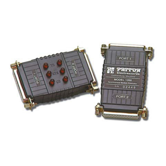
• LEDs monitor data and control signals (Model 1201 only) 2.2 DESCRIPTION Measuring only 5.3 x 2 x 1.2 inches, the Patton Model 1200 is the small- est self-powered synchronous modem eliminator on the market. All power is derived from the RS-232 data signals, so no AC power or bat- teries are required. -
Page 6: Installation
1. Configure according to the instructions listed in section 4.0, “Config- uration” on page 7. 2. Turn off the computer or device to which the Model 1200 is to be connected. 3. Plug the DB-25 connectors directly into the serial ports of your RS- 232 devices. -
Page 7: Configuration
4.0 CONFIGURATION The Model 1200 is equipped with four strapping options that allow config- uration to a wide range of applications. To gain access to the internal straps, loosen the hex nuts on the DB-25 connectors and pry open the case between the plastic shell ears. -
Page 8: Rts/Cts Delay
4.3 RTS/CTS DELAY The RTS/CTS delay straps determine the amount of delay between the time the Model 1200 “sees” RTS and when it sends CTS. In order to emulate either dial-up or leased line modems, you can set this strap at either no delay, 6.6mS or 53mS. -
Page 9: Operation
Once you have configured the Model 1200 properly (see section 4.0, “Configuration” on page 7) and plugged it into your equipment, you are ready to operate the unit. After the Model 1200 is properly installed, it should operate transparently—as if it were a standard cable connection. -
Page 10: A Specifications
APPENDIX A SPECIFICATIONS A.1 DATA RATES Selectable: 1200, 2400, 4800, 9600, 19200, 38400 A.2 CLOCKING Internal or external A.3 GROUNDING Protective ground (pin 1) may be strapped to signal ground (pin 7) A.4 RANGE 300 feet on either side (for a total of 600 feet) at 9600 bps, range extends linearly for lower bit rates and decreases for higher bit rates A.5 FUNCTIONAL... -
Page 11: B Block Diagram
APPENDIX B BLOCK DIAGRAM Copyright © 2001 Patton Electronics Company All Rights Reserved. - Page 12 Dear Valued Customer, Thank you for purchasing Patton Electronics products! We do appreci- ate your business. I trust that you find this user manual helpful. We manufacture one of the widest selections of data communications products in the world including CSU/DSU's, network termination units, powered and self-powered short range modems, fiber optic modems, interface converters, baluns, electronic data switches, data-line surge protectors, multiplexers, transceivers, hubs, print servers and much...
Need help?
Do you have a question about the 1200 and is the answer not in the manual?
Questions and answers