
Related Manuals for Patton electronics 1226


Summary of Contents for Patton electronics 1226
- Page 1 Parallel Short Range Modem SALES OFFICE Part# 07M1226-B (301) 975-1000 Doc# 104031UB Revised 08/13/99 TECHNICAL SUPPORT (301) 975-1007 http://www.patton.com...
-
Page 2: Radio And Tv Interference
Model 1226 immunity to ground loops that would otherwise hamper on different branches). between-building communications. The Model 1226 always works in pairs: One unit is plugged into 1.2 SERVICE the PC’s parallel port and a second unit is plugged into the output device’s parallel port. -
Page 3: Detailed Switch Settings
The following instructions will help This section provides detailed information about the function of you set up and install the Model 1226 properly. If you have any each DIP switch and lists all possible settings. - Page 4 (Parallel to Serial/ Serial to Parallel) When connecting a Model 1226 to a Model 1060, you need to configure both units. First, set the DIP switches on the Model 1226 as indicated in Section 3.1.1. Then configure the Model 1060 by following the instructions below.
-
Page 5: Four-Wire Cable Connection Via Terminal Blocks
When connecting two Model 1226s, it is necessary to use a “cross- over” cable. The diagram below shows how a crossover cable should The Model 1226 is designed to be easy to use. After configuring be constructed for an environment where both Model 1226s use a the DIP switches, connect the two twisted pairs using one of three 4-wire RJ-11 or RJ-45 connector (RJ-45 is shown below). -
Page 6: Operation
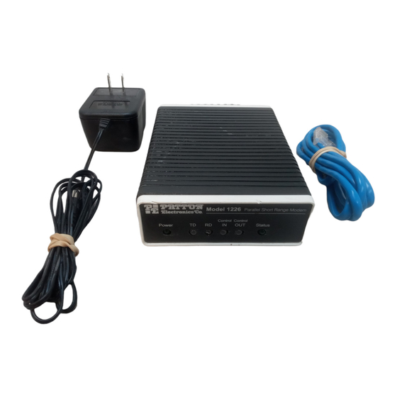
5.1 LED STATUS MONITORS ground wire is not necessary for proper operation of these units. The Model 1226 features six front panel status LEDs that indicate When you have finished connecting the telephone line to units at the condition of the modem and communication link. Figure 5 shows the front panel location of each LED. -
Page 7: Specifications
Apply AC power to the Model 1226 by plugging the separate AC Dimensions: 5.90”l x 4.17”w x 1.61”h power adapter into the rear panel outlet of the Model 1226, and then into an acceptable AC power outlet. Make sure you connect the parallel Weight: Approximately 16 oz. -
Page 8: Parallel Pin Configurations
PARALLEL PIN CONFIGURATIONS BLOCK DIAGRAM SOURCE TRANSMITTER / RECEIVER (DB-25) SOURCE Common Return / Ground -25 Common Return / Ground -24 11- Busy (Active HIGH) Printer Common Return / Ground -23 10- Acknowledge (Active LOW) Printer Common Return / Ground -22 9- Data Bit 8 (MSB) Computer Common...
Need help?
Do you have a question about the 1226 and is the answer not in the manual?
Questions and answers