
Related Manuals for Patton electronics 1004A


Summary of Contents for Patton electronics 1004A
- Page 1 USER MANUAL MODEL 1004A High Speed, Multipoint Short Range Modem SALES OFFICE Part# 07M1004A-C (301) 975-1000 Doc# 047031U, Rev. D TECHNICAL SUPPORT Revised 1/22/08 C E R T I F I E D (301) 975-1007 An ISO-9001 http://www.patton.com Certified Company...
- Page 2 The Model 1004A has been tested and found to comply with the limits for a Class A computing device in accordance...
- Page 3 Packages received without an RMA number will not be accepted. Patton Electronics’ technical staff is also available to answer any questions that might arise concerning the installation or use of your Model 1004A. Technical Service hours: 8AM to 5PM EST, Monday through Friday.
- Page 4 Distances up to 15.0 miles are attainable at lower data rates (1.2 Kbps, 19 AWG twisted pair). The Model 1004A can handle up to 50 terminal drops in a multipoint polling environment. For RS-485 and serial printer applications requiring hardware handshaking, the Model 1004A passes one control signal in each direction.
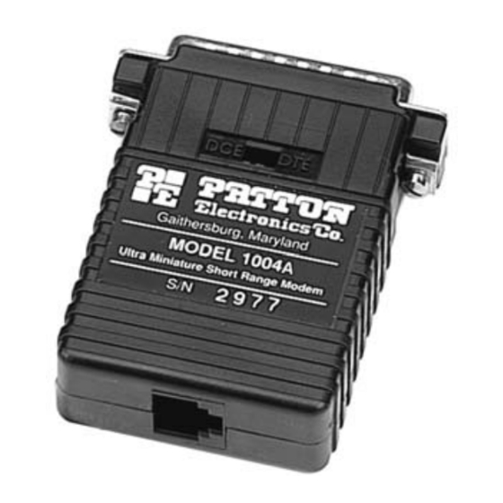
- Page 5 Figure 1. Top view of Model 1004A board, showing DCE/DTE switch. Figure 2 (below) shows the location of the eight position DIP switch on the underside of the Model 1004A PC board. Figure 3 (opposite page) shows the orientation of the eight position DIP switch, with respect to ON/OFF positions.
- Page 6 For your convenience, the Model 1004A has an externally accessible DCE/DTE switch. If the device connected to the Model 1004A is a modem or multiplexer (or is wired like one), set the switch to “DTE”. This setting causes the Model 1004A to behave like Data Terminal Equipment and transmit data on pin 2.
- Page 7 Intermediate Impedance High Impedance S1-3: RTS/CTS Delay The setting for switch S1-3 determines the amount of delay between the time the Model 1004A “sees” RTS and when it sends CTS. Note: RTS/CTS Delay setting should be based upon transmission timing. S1-3...
- Page 8 Low (120 Ohm) High (16 kOhm typical) S1-7 and S1-8: 2-Wire/4-Wire Modes Switches S1-7 and S1-8 are set together to determine whether the Model 1004A is in 2-wire or 4-wire operating mode. Note: 2-wire mode is half-duplex only. S1-7 S1-8...
- Page 9 3.4 CONFIGURATION SWITCH APPLICATIONS The switch settings generally needed to configure the Model 1004A for various applications are shown in the table below. Note: Do not change switch settings until you have carefully read Section 3.3. TYPICAL MODEL 1004A APPLICATIONS...
- Page 10 If your application requires you to connect one or two pairs of bare wires to the Model 1004A, you will need to open the case to access the terminal blocks. The following instructions will tell you how to open the case, connect the bare wires to the terminal blocks and fasten the strain relief collar in place so the wires won't pull loose.
- Page 11 7. If there is a shield around the telephone cable, it may be connected to “G” on the terminal block. To avoid ground loops, we recommend connecting the shield at the computer end only. A ground wire is not necessary for proper operation of the Model 1004A.
- Page 12 8. When you finish connecting the wires to the terminal block, the assembly should resemble the diagram below: 9. Place the 2 halves of the strain relief assembly on either side of the telephone wire and press together very lightly. Slide the assembly so that it is about 2 inches from the terminal posts and press together firmly.
- Page 13 10. Insert the strain relief assembly and wire into the slot in the bottom half of the modem case. Set it into the recess in the case. 11. BEND the top half of the case as necessary to place it over the strain relief assembly.
- Page 14 4.1.2 TWISTED PAIR CONNECTION USING RJ-11 OR RJ-45 The RJ-11 and RJ-45 connectors on the Model 1004A’s twisted pair interface are pre-wired for a standard TELCO wiring environment. The signal/pin relationships are shown below: RJ-11 SIGNAL RJ-45 SIGNAL 1 ....GND †...
- Page 15 Connection to ground is optional 4.2 WIRING FOR MULTIPOINT CIRCUITS The Model 1004A supports multi-point applications using either a star or daisy chain topology. Both topologies require special wiring, as well as specific DIP switch settings for master and slave units. Note: Refer to Section 3.2.2 for multipoint DIP switch settings.
- Page 16 XMT- Figure 5. Star wiring for Model 1004A host and slaves Figure 5 (below) shows how to wire the two-pair cables properly for a Model 1004A star topology. Note that the ground connection is not needed. 4.2.2 DAISY CHAIN TOPOLOGY Using a daisy chain topology, you may connect several Model 1004As together in a master/slave arrangement.
- Page 18 DB-25 port of the RS-232 device. Remember to insert and tighten the two captive connector screws. (Note: If you must use a cable to connect the Model 1004A to the RS-232 device, make sure it is a straight through cable of the shortest possible length—we recommend 6 feet or less).
-
Page 19: Control Signals
APPENDIX A PATTON MODEL 1004 SPECIFICATIONS DIRECTION “DCE” SETTING DIRECTION 1- (FG) Frame Ground 2- (TD) Transmit Data To 1004A 3- (RD) Receive Data From 1004A 4- (RTS) Request to Send To 1004A 5- (CTS) Clear to Send From 1004A... - Page 20 Dear Valued Customer, Thank you for purchasing Patton Electronics products! We do appreciate your business. I trust that you find this user manual helpful. We manufacture one of the widest selections of data communications products in the world including CSU/DSU's, network termination units, powered and self-powered short range modems, fiber optic modems, interface converters, baluns, electronic data switches, data-line surge protectors, multiplexers, transceivers, hubs, print servers and much more.
Need help?
Do you have a question about the 1004A and is the answer not in the manual?
Questions and answers