Table of Contents
Advertisement
Advertisement
Table of Contents

Related Manuals for Trane BCU Operator Display


Summary of Contents for Trane BCU Operator Display
- Page 1 Operations BCU Operator Display BMTW-SVU02C-EN...
- Page 3 Operations BCU Operator Display ™ Tracer Summit BMTW-SVU02C-EN June 2006...
- Page 4 Although Trane has tested the described in this guide, no guarantee is offered that the hardware and software are error free. Trane reserves the right to revise this publication at any time and to make changes to its content without obligation to notify any per- son of such revision or change.
- Page 5 NOTICE: Warnings and Cautions appear at appropriate sections throughout this manual. Read these carefully. WARNING Indicates a potentially hazardous situation, which, if not avoided, could result in death or serious injury. CAUTION Indicates a potentially hazardous situation, which, if not avoided, may result in minor or moderate injury. It may also be used to alert against unsafe practices.
-
Page 7: Table Of Contents
Contents Chapter 1 BCU Operator Display Overview....1 Using the Touch Screen ........2 Home Screen . - Page 8 Contents Viewing the Event Log ........30 Acknowledging an Event .
- Page 9 Contents Chapter 7 Maintaining the Operator-Display Touch Screen 59 Cleaning the Operator-Display Touch Screen..... 59 Glossary ....... . . 61 Appendix A Declaration of Conformity .
- Page 10 Contents BMTW-SVU02C-EN...
-
Page 11: Chapter 1 Bcu Operator Display Overview
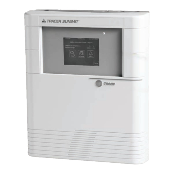
BCU Operator Display Overview The BCU operator display is a liquid crystal display (LCD) touch screen. It is installed in Tracer Summit BMTW building control units (BCUs) as an option (see Figure 1). The operator-display touch screen enables you to perform most of the Tracer Summit PC Workstation daily activities at the BCU. -
Page 12: Using The Touch Screen
BCU Operator Display Overview Using the Touch Screen The operator-display touch screen uses five different screen types, as well as selection buttons and navigation buttons to view and change system status information. The five screen types are the home screen, standard screens, custom screens, confirmation screens, and the security screen. - Page 13 Using the Touch Screen Table 1: Home Screen Task Button Descriptions Button Description Press the View button to: • View and change setpoints • Perform manual equipment overrides • View diagnostics • View equipment information For detailed information about using the View function, see “Viewing and Changing System Status Information”on page 9.
-
Page 14: Selection And Navigation Buttons
BCU Operator Display Overview Selection and Navigation Buttons You navigate through the touch screens by using selection buttons and navigation buttons (see Figure 3). Selection buttons enable you to select an item to view or edit. Navigation buttons enable you to page through a list of items, return to a previous page, or return to the home screen. - Page 15 Using the Touch Screen Table 2: Navigation button descriptions Button Description The Home button returns the display to the home screen. The Back button returns the display to the previous screen. The Top of List button shows items at the top of the current list. (This button only appears when there are three or more pages.) The Top of List and Bottom of List buttons appear grayed-out if you are viewing the top or bottom of the list.
-
Page 16: Operator Display Screens
Standard Screens Standard screens are a part of the Tracer Summit BCU operator display software. (See Appendix B on page 67 for a list of standard screens avail- able at the operator display.) Standard screens are identified by a title bar at the top of each screen (see Figure 4). -
Page 17: Confirmation Screens
Figure 6 shows an exam- ple of a confirmation screen for changing a setpoint. The Trane installer or programmer has the option of disabling non-criti- cal confirmation screens. Consequently, you may not be prompted to con- firm some changes. -
Page 18: Security Screen
BCU Operator Display Overview Security Screen The operator-display security screen appears when a password is required to edit a task (see Figure 7). The password is a four-to-eight- digit number. Contact your supervisor for more information. Figure 7: Security Screen To enter a password: 1. -
Page 19: Chapter 2 Viewing & Changing System Status Information
Summit equipment (see Appendix B on page 67). Custom Screens If the Trane installer or programmer has selected custom screens for use at the operator display, then a custom screen is the first screen that dis- plays after you press the view button on the home screen. Custom screens can be linked to standard screens by the use of a navigation button (see Figure 5 on page 7). -
Page 20: Using The View Screens
The View Equipment screen enables you to view equipment status by using three different sort methods: Building Area, Name of Equipment and Equipment Type. Note: The building area sort method only appears if the Trane installer or programmer has assigned areas to the operator dis- play. Using the View Screens There are three sort methods for viewing and changing system status: •... -
Page 21: View By Name Of Equipment
Using the View Screens View by Name of Equipment Figure 10 on page 13 shows an example of how to view equipment by using the equipment name. This sort method assumes that you know the equipment by name. The step-by-step procedure for viewing by equip- ment name starts on page 16. - Page 22 Viewing and Changing System Status Information Figure 9: Sorting by Building Area—Example Screens Area Screen #1 This screen displays a list of the areas in alphabetical order. Select the building area Area Screen #2 This screen displays a list of equipment in alphabetical order for the area you want to view.
- Page 23 Using the View Screens Figure 10: Sorting by Equipment Name—Example Screens Equipment Name This screen displays a list of equipment in alphabetical order. Select equipment by name UCM Main Screen This screen displays the operating conditions of the equipment. BMTW-SVU02C-EN...
- Page 24 Viewing and Changing System Status Information Figure 11: Sorting by Equipment Type—Example Screens Screen #1—Equipment Type This screen displays equipment by type in alphabetical order. Select equipment type Screen #2—Equipment Name This screen displays all the equipment of a particular type in alphabetical order.
-
Page 25: Viewing System Status Information
Viewing System Status Information Viewing System Status Information Use the following procedures to view equipment status using one of the three sort methods: Viewing equipment by building area • Viewing equipment by equipment name • Viewing equipment by equipment type •... -
Page 26: Viewing Equipment By Name
2. Press the Equipment Type button. The View-By Equipment Type screen displays, listing in alphabetical order the types of equipment available at the BCU operator display. 3. Select the equipment type button to view a list of equipment of that type. -
Page 27: Viewing The Ucm Main Screen
Viewing System Status Information change system information, see “Changing System Values” on page 18. Note: Some equipment may not have a unit control module (UCM) main screen, More Details screen, or Unit Summary informa- tion associated with it. The UCM main screen may or may not have a graphic (picture of the equipment) associated with it. -
Page 28: Changing System Values
Viewing and Changing System Status Information Changing System Values With the operator display, you can change system values in several ways: Change setpoints • Override the status of equipment • Override binary or analog outputs • Release override control • Changing Unit Setpoints 1. - Page 29 Changing System Values Figure 14: VAV Unit Setpoints Screen Operating mode of the UCM Selection Property names for the buttons equipment being viewed 5. Press the selection button to change the setpoint. A numerical keypad displays (see Figure 15). Note: If there is no selection button for a setpoint, you cannot change or edit that setpoint (for example in Figure 14 you cannot edit the setpoints for Unoccupied Cool Setpoint or Unoccupied Heat...
-
Page 30: Overriding System Values
Viewing and Changing System Status Information 8. Press Yes to confirm your changes and return to the Setpoints screen. Note: To clear your entry, press the Clear button. To cancel your entry and return to the previous screen, press the Cancel button. Overriding System Values 1. - Page 31 Changing System Values The override control status for each property is displayed within square brackets. Each property can be controlled to the following con- trol status: Blank—no override status is shown for the present value property • when communications are down. Some properties do not support displaying the control status (for example, properties with more than two states: auto/manual).
-
Page 32: Making A Manual Request
The lowest priority number is 16 and the highest is 1. The default for the BCU operator display is 12. Your priority level depends on the level set by the Trane programmer or installer. -
Page 33: Releasing Control Of The Present Value Override Request
Changing System Values Releasing Control of the Present Value Override Request You can release the Manual Request override for the present value prop- erty. To release control: 1. From the Manual Control screen, press the Present Value button. The present value overrides screen displays. Figure 20 shows an example of a Present Value overrides screen. -
Page 34: Viewing Unit Summary Information
Viewing and Changing System Status Information Viewing Unit Summary Information The Unit Summary screen provides additional information about how a unit is operating. Figure 21 shows the type of information you can find on the Unit Summary screen. Figure 21: Unit Summary Screen To access the Unit Summary Screen: 1. -
Page 35: Viewing Diagnostics
Changing System Values Viewing Diagnostics The BCU operator display lists active diagnostics for most of the equip- ment selected for viewing and editing at the display. Active diagnostics provide information about the state or condition of the equipment that could adversely affect its operating performance. Figure 22 shows the presence of an active diagnostic for a piece of equipment. - Page 36 Viewing and Changing System Status Information Figure 23: Types of Active Diagnostics Manual reset Automatic reset Informational warning To view diagnostics: 1. From the home screen, press the View button. 2. Using one of the sort methods, access the UCM main screen for the equipment you want to view.
-
Page 37: Chapter 3 Handling Alarms And Events
Chapter 3 Handling Alarms and Events The BCU operator display can display all alarms and events received by the BCU event log. The BCU event log is a list of the 100 most recent alarms and events sent to the BCU. The event log lists alarms and events in the order they are received, with the most recent alarms and events displaying at the top of the event log. -
Page 38: Alarm Notification
Figure 24: Alarm Indicator Indicator light The Trane installer or programmer can set up alarms and events to beep when they are received by the operator display. The speaker on the BCU will beep until you press the Alarms button on the home screen. If you exit the event log with an unacknowledged alarm or event, the system will reset the beep-timer to beep again in 60 minutes. - Page 39 Using the Alarms and Events Screens Figure 25: Event Screens Event Log Indicates unacknowledged This screen displays all the alarms or events alarms and events received by the BCU. Indicates events or alarms not viewed List of alarms and events Press to view an alarm or event Event Details #1...
-
Page 40: Viewing The Event Log
Handling Alarms and Events Viewing the Event Log All operator tasks begin at the home screen (see “Home Screen” on page 2). 1. From the home screen, press the Alarms button. The event log list displays (see Figure 25 on page 29). 2. -
Page 41: Chapter 4 Displaying And Editing Schedules
Chapter 4 Displaying and Editing Schedules The BCU operator display schedule function enables you to view and edit schedules. Schedules available at the operator display have been selected for viewing and editing by the Trane installer or programmer. A schedule is a set of events (instructions) that tells the HVAC (heating, ventilating, air conditioning) equipment connected to Tracer Summit what to do and when to do it. -
Page 42: Using The Schedule Screens
Displaying and Editing Schedules Using the Schedule Screens There are nine screens associated with viewing and changing schedules. These screens are: Schedule list Calendar • Basic events • Detailed events • Events editor • Select dates • • Other date •... - Page 43 Using the Schedule Screens Figure 26: Viewing Schedules Schedule List This screen displays all the schedules available for viewing and editing. Select a schedule name Calendar This screen displays the calendar for the current month. The current day is Select a day to view indicated by a bold its schedule button border.
- Page 44 Displaying and Editing Schedules Figure 27: Editing Schedules Detailed Events This screen displays a regular schedule with two events. View the events for this schedule Press to change event start and stop times Event Editor Use this screen to change event times or duration on the detailed events screen.
-
Page 45: Viewing Schedules
Viewing Schedules Viewing Schedules All operator tasks begin at the home screen (see “Home Screen” on page 2). To view a schedule: 4. From the home screen, press the Schedule button. A list of schedules displays. See Figure 26 on page 33. 5. -
Page 46: Selecting Calendar Month And Day
Displaying and Editing Schedules Selecting Calendar Month and Day When you display the calendar screen, the calendar shows the current month and day (see Figure 26 on page 33). You can view the schedule of a different month in two ways: Calendar selection arrows •... - Page 47 Viewing Schedules Figure 30: Other Date Calendar–Day and Year Screen Selection arrows There are three fields associated with changing the date: • • Month Year • Use the selection arrows to move the cursor over that part of the date that you want to change.
-
Page 48: Displaying The Events In A Schedule
Displaying and Editing Schedules 3. At the blinking cursor, use the keypad to enter a different month. The cursor automatically moves to the year field and the keypad changes to display the numerical keypad (see Figure 30 on page 37). 4. - Page 49 Displaying the Events in a Schedule Figure 32: Select Dates Screen Shows current date 3. Apply this change to create an exception or permanent change to the schedule. To create an exception, see “Creating Exceptions” on page 42. To make a permanent change to the schedule, see “Making Permanent Changes to a Schedule”...
-
Page 50: Adding An Event To A Schedule
Displaying and Editing Schedules 2. Use the keypad to enter the new time or duration. Use the AM or PM buttons to indicate the time of day. Note: If you need to clear your entry, press the Clear button. Press the Cancel button to return to the previous screen without making any changes. -
Page 51: Deleting An Event From A Schedule
Displaying the Events in a Schedule 3. Select the Add button to add an event to the schedule. A list of avail- able events displays (see Figure 35). Figure 35: Add Event Screen—Example 4. Select the event you want to add to the schedule. The events editor displays (see Figure 27 on page 34). -
Page 52: Creating Exceptions
Displaying and Editing Schedules Figure 36: Remove Event Screen—Example 4. Select the event you want to remove from the schedule. The operator display returns you to the basic or detailed events screen. 5. Press the OK Select Dates button. The select dates screen displays (see Figure 27 on page 34). -
Page 53: Creating A One-Time Exception
Creating Exceptions Figure 37: Exception Schedule in Effect Type of schedule in effect Creating a One-time Exception To access the basic events or detailed events screen, see “Viewing Sched- ules” on page 35. 1. From the basic or detailed events screen, change the daily events to represent the events of the exception. -
Page 54: Removing An Exception From A Selected Date
Displaying and Editing Schedules Figure 38: Calendar Showing Exception for Specific Dates Indicates an exception 5. Press the end date. A confirmation screen displays. 6. Press Yes to apply the exception to the schedule for the specified dates. The operator display returns you to the basic or detailed events screen. -
Page 55: Making Permanent Changes To A Schedule
Making Permanent Changes to a Schedule Making Permanent Changes to a Schedule A permanent change allows you to permanently apply schedule changes to one or more days in the schedule. To make permanent changes to a schedule: To access the basic events or detailed events screen, see “Viewing Sched- ules”... -
Page 56: Changing A Holiday Schedule
Displaying and Editing Schedules Changing a Holiday Schedule You can change the events scheduled for a holiday, but you cannot create or delete a holiday from the operator display. To access the calendar screen, see “Viewing Schedules” on page 35. 1. -
Page 57: Chapter 5 Making A Timed Override Request
You can start or cancel a timed override (TOV) request for an area from the BCU operator display. A TOV button appears on the home screen when this function is available (see “Home Screen” on page 2). TOV is set up and enabled from a Tracer Summit PC Workstation by a Trane pro- grammer or installer. - Page 58 Making a Timed Override Request Figure 41: TOV screens TOV area list This screen displays a list of areas available for timed override requests. Select an area name Timed Override Status—Not Active Use this screen to start a TOV request and set the duration of the TOV.
-
Page 59: Starting A Tov Request
The duration is changed in increments or dec- rements of 15 minutes. Note: The Trane installer or programmer determines the maximum possible duration when setting up TOV in Tracer Summit. 3. Press the Start Timed Override button to start your timed override request. - Page 60 Making a Timed Override Request BMTW-SVU02C-EN...
-
Page 61: Chapter 6 Operator Display Setup Options
Chapter 6 Operator Display Setup Options The BCU operator display setup function enables you to change BCU and operator display system settings (see Figure 42). The setup function enables you to: • Set time and date • Set the time format Adjust brightness •... -
Page 62: Setting The Time And Date
Operator Display Setup Options Setting the Time and Date You can set the time and date for the BCU operator display using the time and date function. The time and date are displayed on the home screen. To set the time: 1. - Page 63 Setting the Time and Date To set the date: 1. From the home screen press the Setup button. The Setup menu dis- plays (see Figure 42 on page 51). 2. Press the Set Date button. The Set System Date screen displays (see Figure 44).
- Page 64 Operator Display Setup Options Figure 45: Calendar-Month Screen 4. At the blinking cursor, use the keypad to enter a different month. The cursor automatically moves to the year field and the keypad changes to display the numerical keypad (see Figure 44 on page 53). 5.
-
Page 65: Adjusting Brightness
Adjusting Brightness 2. Press a new format to display the time differently (12 hour or 24 hour). The operator display returns you to the Setup menu, where you can view the new format from the Set Time button. Adjusting Brightness The following procedure enables you to adjust the brightness of the operator-display touch screen. -
Page 66: Calibrating The Operator-Display
Operator Display Setup Options Calibrating the Operator-Display Touch Screen Occasionally, you may need to recalibrate the touch screen for accuracy of the touch targets. To recalibrate the touch screen: 1. From the home screen press the Setup button. The Setup menu dis- plays (see Figure 42 on page 51). -
Page 67: Changing The Display Language
Changing the Display Language Figure 49: Calibration Touch Target #2 Calibration target 4. Again, touch the target with the object. Hold until the beeping stops. The touch screen is now calibrated and the operator display returns you to the Setup menu. Changing the Display Language You can change the language in which text is displayed on the BCU oper- ator display. -
Page 68: Logging Off The Operator Display
The display language option is only available on BMTXs with images of version 17 or higher. Logging Off the Operator Display The BCU operator display automatically logs off after 30 minutes of not recording any touch inputs to the touch screen. To manually log off the operator display: 1. -
Page 69: Chapter 7 Maintaining The Operator-Display Touch Screen
Chapter 7 Maintaining the Operator- Display Touch Screen The only maintenance necessary for the BCU operator display is to occasionally clean the touch screen (see Figure 51). Figure 51: BCU Operator-Display Touch Screen Operator-display touch screen Cleaning the Operator-Display Touch Screen To clean the touch screen, wipe it off with a non-abrasive cloth. - Page 70 Maintaining the Operator-Display Touch Screen BMTW-SVU02C-EN...
-
Page 71: Glossary
Glossary Alarms A notification that HVAC equipment is not operating correctly. For exam- ple, an alarm is generated when communication is down between an HVAC unit and the BCU, or when a filter on an HVAC unit is dirty. BMTW BCU See Building control unit Building control unit (BCU) The BCU is a panel that communicates with and controls the unit control... - Page 72 Glossary • Whether the alarm or event was generated by the operator (for exam- ple, an operator logs on) or by Tracer Summit PC Workstation soft- ware (for example, a pump shuts down) Name of the PC workstation at which operator-generated events •...
- Page 73 Also, changes made offline will be updated the next time the PC Workstation is online with the BCU operator display. Property One element of an object’s characteristic information. This information element can be viewed, referenced, and applied throughout the Tracer Summit system.
- Page 74 Timed override (TOV) Timed override enables building occupants and management staff to override HVAC and lighting equipment to an occupancy status. You can perform overrides from a Trane zone sensor, a PC Workstation, or a BCU operator display. Touch screen A transparent overlay on an LCD or cathode ray tube (CRT) that is sensi- tive to touch by a finger or stylus.
-
Page 75: Appendix A Declaration Of Conformity
Appendix A Declaration of Conformity This appendix provides the Declaration of Conformity statement for the BCU operator display. BMTW-SVU02C-EN... - Page 76 Electromagnetic Emission 09/05/96 Electromagnetic Immunity 07/22/94 Electrical Safety 08/19/99 St. Paul Minnesota USA Craig Kasl Design/Compliance Engineer Mark of Compliance European Contact Societe Trane (Epinal, France) 1, rue des Ameriques, B.P. 6 F-88191 Golbey Cedex, France Phone: 33-329-31-7300 Fax: 33-329-81-2498 BMTW-SVU02C-EN...
-
Page 77: Appendix B Standard Screens
Standard screens may or may not have monochrome bitmaps (picture of equipment) associated with them. Note: The Trane installer or programmer selects the equipment that is displayed at the operator display. If a particular piece of equipment has not been selected, the associated standard screen is not available at the operator display. -
Page 78: Standard Screens With Monochrome Bitmaps
Standard Screens Standard Screens with Monochrome Bitmaps Absorption Chiller (UCP2) • CenTraVac (UCP1) • • Centrifugal Chiller (UCP2) • Commercial Self Contained (CSC) Discharge Air Controller (DAC) • Helical Rotary Chiller (UCP2) • Horizon Absorption Chiller • IntelliPak Airhandler • IntelliPak Rooftop •... -
Page 79: Index
Exception in a schedule Definition, 31 Exceptions Back button Creating, 42 Description of, 5 Removing, 44 BCU operator display, 1 Logging off, 58 Setup options for, 51 BMTW BCU, 1 Holiday Bottom of List button Changing events for, 46 Description of, 5... - Page 80 Index Definition, 63 Override control status Task buttons description, 21 Description of, 3 Overrides Time and Date, setting up, 52 Making a manual request, 22 Timed override System values, 20 Canceling a request, 49 Definition of, 64 Restarting a request, 49 Starting a request, 49 Passwords Using the TOV screens, 47...
- Page 82 La Crosse An American Standard Company www.trane.com Trane has a policy of continuous product and product data improvement and reserves the right to For more information contact change design and specifications without notice. Only qualified technicians should perform the installa- your local district office or tion and servicing of equipment referred to in this publication.
Need help?
Do you have a question about the BCU Operator Display and is the answer not in the manual?
Questions and answers