Trane CVHE Information Manual
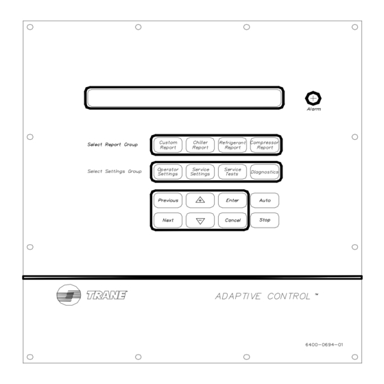
Clear language display
Hide thumbs
Also See for CVHE:
- Troubleshooting manual (128 pages) ,
- Installation, operation and maintenance manual (100 pages) ,
- Installation manual (68 pages)
Table of Contents
Advertisement
Information
Manual
Clear Language Display
Water-Cooled, Hermetic CenTraVac®
Clear Language Display for UCP2 and
FastPak™ Control Panels
Models
CVHE, CVHF, CVHG, CVRB, CVRC
50 and 60 Hz
Cooling-Only and Heat Recovery, Direct-Drive CenTraVacs
with UCP2 Control panels
X39470756-02
CVHE-CLD-1A
February 2000
Advertisement
Table of Contents

Related Manuals for Trane CVHE


Summary of Contents for Trane CVHE
- Page 1 Manual Clear Language Display Water-Cooled, Hermetic CenTraVac® Clear Language Display for UCP2 and FastPak™ Control Panels Models CVHE, CVHF, CVHG, CVRB, CVRC 50 and 60 Hz Cooling-Only and Heat Recovery, Direct-Drive CenTraVacs with UCP2 Control panels CVHE-CLD-1A X39470756-02 February 2000...
-
Page 2: Table Of Contents
Contents General ..............1 Refrigerant Report ..........15 Literature Change History ........1 Report Heading ..........15 About This Manual ..........1 Evaporator and Condenser Refrigerant LCD Display ............1 Pressure ............15 Keypad ..............1 Saturated Evap Temperature/Evap Refrigerant LED Alarm ............ - Page 3 Purge Operating Mode ........20 Purge Service Excessive Pumpout Time Of Day Setting ......... 21 Override Timer ..........32 Front Panel Chilled Water Setpoint ....21 Purge Low Chiller Sat. Cond. Liquid Temp. Protec- Front Panel Hot Water Setpoint ......22 tion Enable ............
- Page 4 Programmable Analog Output ......47 Manual Loading/Unloading Duty Cycle .... 57 Programmable Relay Outputs ......48 AF Manual Speed Control - CVHE/F/G Only ..57 Current Transducer Setpoint ......48 AF Compressor Speed Command - CVHE/F/G Current Transducer at 100% RLA ..... 48 Only ..............
- Page 5 AF Boundary Pressure Coefficient/AF Pressure Co- efficient - CVHE/F/G Only ....... 58 AF Re-Optimization Timer Time Remaining- CVHE/ F/G Only ............58 Module Software Revision Levels ..... 58 Diagnostics Menu ..........59 Diagnostics Group Heading ......59 Menu Settings Password ........59 Diagnostics and Annunciation ......
-
Page 6: General
General General Literature Change History LED Alarm CVHE-CLD-1 (February 1995) In addition to the alpha-numeric LCD display, there's a single discrete LED on the human interface. The Application of the Clear Language Display to the red LED flashes on-off whenever a latching... -
Page 7: Control System
All wiring to the modules are to pluggable Figure 2 ) communicate with each other through the terminal blocks. Interprocessor Communication Circuit (IPC). Figure 2 UCP2 Control Panel I/O Module Stepper Mod Options Mod Chiller Mod Circuit Mod CVHE-CLD-1A... -
Page 8: Custom Report
Custom Report Custom Report Custom Report Group Reports are added to the custom report group by pressing the <+> key when the desired report is being displayed from its normal report location. Reports are removed from the custom report group by pressing the <->... -
Page 9: Ashrae Guideline 3 Report
(Table 1) . In some cases, an associated timer or system parameter will be displayed that assures the transition to an expected mode is in progress, particularly during the unit start-up sequence. CVHE-CLD-1A... - Page 10 ASHRAE Guideline 3 Report Table 1 Operating Modes Operating Mode Display* Operating Mode Display* Unit Operation (First Line/Second Line) Unit Operation (First Line/Second Line) Resetting Unit Is Running Capacity Limited By Phase Unbalance Local Stop: Cannot Be Overridden By Unit Is Running Any External Or Remote Device Capacity Limited By High Cond Press Remote Display Stop: Chiller May Be...
- Page 11 Where (Y) can equal 123, 11, 22, 134a, or 12. Purge Pumpout Rate/Purge Max Pumpout Rate The following screen(s) does not appear if the selected Purge Control/Type is “Stand-Alone Purge.” Purge Pumpout Rate: xxx.x Min/24Hrs Purge Max Pumpout Rate: xxx.x Min/24Hrs CVHE-CLD-1A...
- Page 12 ASHRAE Guideline 3 Report Purge Total Pumpout Time/ Purge Total Run Discharge Oil Pressure, Oil Tank Pressure Time This screen is only displayed if the “Oil Pressure The following screen(s) does not appear if the Protection” setpoint is set to “Transducer” or “Xducer selected Purge Control/Type is “Stand-Alone Purge.”...
- Page 13 UCM. Cond Differential Wtr Press: xx.x psid/kPa Press (Next)(Previous) To Continue Chilled Water Flow Switch Status: Possible values for [y] are: Flow Switch is Open/No Flow or Flow Switch is Closed/Flow. CVHE-CLD-1A...
- Page 14 ASHRAE Guideline 3 Report Condenser Water Flow The following will be displayed only if the Differential Water Sensing Option is installed. Approx Condenser Water Flow: xxx.x gpm/lpm Press (Next)(Previous) To Continue The possible values for units are “gpm” or “lpm.” Condenser Water Flow Switch Status The following screen is displayed only if the Differential Water Pressure Sensor Option is not...
-
Page 15: Chiller Report
Unit Is Free Cooling Starting Is Inhibited By Restart Inhibit Timer: Time Remaining MIN:SEC Establishing Cond Water Flow Establishing Oil Pressure Establishing Cond Water Flow PreLubrication Time: MIN:SEC Cond Water Is Flowing Establishing Oil Pressure Starting Unit Is Running CVHE-CLD-1A... - Page 16 Chiller Report Unit Is Running Capacity Limited By High Current Unit Is Running Capacity Limited By Phase Unbalance Unit Is Running Capacity Limited By High Cond Press Unit Is Running Capacity Limited By Low Evap Temp Unit Is Running; Capacity Limited By Vane Open Travel Stop Unit is Running;...
-
Page 17: Active Chilled Water Setpoint/Evap Leaving Water Temp
Cond Leaving Water Temp: xxx.x f/c Active Chilled Water Setpoint/Chilled Water Setpoint Source Active Chilled Water Setpoint: xxx.x f/c [settings source]CWS: xxx.x f/c Settings source will be one of the following: Front Panel, Tracer, External Source, or Duplex Control. CVHE-CLD-1A... -
Page 18: Evaporator Entering And Leaving Water Temperatures
Chiller Report Evaporator Entering and Leaving Water Chiller Tons Temperatures The following will be displayed only if the Differential Water Sensing Option is installed. Evap Entering Water Temp: xxx.x f/c Evap Leaving Water Temp: xxx.x f/c Approximate Chiller Capacity: xxxx Tons/KW Press (Next)(Previous) To Continue Cond Entering and Leaving Water Temps The possible values for units are “Tons”... -
Page 19: Current Limit Setpoint Source
Panel, Tracer, or External Source. Ice Termination Setpoint Source The following will be displayed when/if remote computer is installed. Ice Termn Setpt Source: [settings source] Press (Next)(Previous) To Continue Settings source will be one of the following: Front Panel or Tracer. CVHE-CLD-1A... -
Page 20: Refrigerant Report
Refrigerant Report Refrigerant Report Report Heading Purge Operating Mode/Purge Status The following screen(s) does not appear if the selected Purge Control/Type is “Stand-Alone Purge.” Refrigerant Temp & Pressure Report Press (Next)(Previous) To Continue Purge Operating Mode: [Mode] Purge Status: [Status] Evaporator and Condenser Refrigerant Pressure Possible values of [Mode] are: Auto, Stop, On, or... -
Page 21: Purge Suction Temp/Purge Liquid Temp
If the mode selected is not Adaptive, then the time in the bottom line is dashed out. Last 5 Cycle Pumpout Avg,Interval From Shtdn To 3 Hrs After Shtdn: xxx.x Min 30 Day Pumpout Avg, Interval From 3Hrs After Shtdn To Next Start: xxx.x Min CVHE-CLD-1A... -
Page 22: Refrigerant Monitor
Refrigerant Report Refrigerant Monitor The following is displayed if the IPC Refrigerant Monitor Auxiliary input option is installed. The following item is displayed if the Analog Refrigerant Monitor option is installed. Rfgt Mon Auxiliary Input: XX.X mA Press (Next) (Previous) To Continue Refrigerant Monitor: xxx.x PPM Press (Next)(Previous) To Continue Approach Temperature... -
Page 23: Compressor Report
Inlet Guide Vane Position xxx.x % Open Inlet Guide Vane Position xx.x degrees AF Compressor Speed Command: xx Hz AF Compressor Speed Command: xxxx RPM Range of values is 2520 to 3600 rpm in increments of 1 rpm. Factory default is 3600 rpm. CVHE-CLD-1A... -
Page 24: Compressor Phase Currents % Rla
Compressor Report Compressor Phase Currents % RLA Compressor Winding Temperatures Compressor Phase Currents - % RLA Compressor Winding Temperatures A xxxx.x % B xxxx.x % C xxxx.x % W1 xxx f/c W2 xxx f/c W3 xxx f/c Compressor Line Currents Amps Compressor Starts and Running Time The starts and hours counters are displayed as follows:... -
Page 25: Operator Settings
Settings Group Keys The possible values for status are “Locked” or “Unlocked”. If the password status is locked, the The four settings Group Keys for CVHE/CVHF/ password message will be “Enter Password to CVHG are as follows: Unlock”. The user will then depress (-)(+)(-)(+)(-)(+) followed by the <Enter>... -
Page 26: Time Of Day Setting
Operator Settings Time Of Day Setting Current Time/Date HH:MM xm Mon XX,XXXX Current Time/Date HH:MM xm Mon,XX XXXX To Change Month, Press(+)(-) & (Enter) (Enter) to Change : (Next) to Continue The top level "CurrentTime/Date" will be displayed when this screen is first selected. Pressing the <Next>... -
Page 27: Front Panel Hot Water Setpoint
T and max reset The Print Command is Being setpoint to design. Sent to the Printer 3 Chilled water is reset based on either return water temperature or outdoor air temperature. 4 This screen does not appear when the chiller is CVHE-CLD-1A... -
Page 28: Reset Ratio
Operator Settings under Duplex Control and it is Compressor B. Press (+)(-) to Change Setting The values for Maximum Reset for each of the reset Reset Ratio types are: This is the aggressive value. A higher number is a Maximum Increment quicker response. -
Page 29: Chilled Water Setpoint Source
If the Tracer Option is installed, the word “Default” Possible values of [source] are: “None” (Factory will appear in front of the setpoint source. Default), “Use Front Panel Setpoints”, “Override Tracer, and Use Default Setpoints” (Available only if Tracer Option installed). [Default] Hot Water Setpoint Source: [source] CVHE-CLD-1A... -
Page 30: Service Settings (Non Password Protected Service Settings Group)
Service Settings (Non Password Protected Service Settings Group) Service Settings (Non Password Protected Service Settings Group) Important! FACTORY DEFAULT SETTINGS: Menu Service Setting Group Heading items that are programmable using the keypad may have a selectable choice that is listed as Factory Default. -
Page 31: Keypad/Display Lockout
If the <Enter> key is pressed to lock the keypad, the feature is enabled. following message is displayed, and all further input from the keypad is ignored, including the <Stop> key, until the password is entered. The password consists Press (Enter) to Lock Display & Keypad CVHE-CLD-1A... -
Page 32: Language Setting
Service Settings (Non Password Protected Service Settings Group) of pressing the <Previous> and <Enter> keys at the Display Menu Headings Enable same time. Display Menu Headings: [d/e] ******DISPLAY AND KEYPAD ARE LOCKED****** Press (+)(-) to Change Setting ********ENTER PASSWORD TO UNLOCK******** The Factory Default value is Enabled. -
Page 33: Evap/Cond Pump Off Delay Time
Range of values is 1 to 24 Hours in increments of 1 Press (+)(-) to Change Setting Hour. Factory Default is 8 Hours. The choices for Status are: XON/XOFF (Factory Default), DTR, RTS, and None. Print on Diagnostic: [Status] Press (+)(-) to Change Setting CVHE-CLD-1A... -
Page 34: Clear Restart Inhibit Timer
Service Settings (Non Password Protected Service Settings Group) Clear Restart Inhibit Timer Press (Enter) to Clear the Restart Inhibit Timer When <Enter> is pushed, a 2 second message appears as shown below and then returns to above screen. Restart Inhibit Timer Has Been Cleared Information Manual... -
Page 35: Field Startup
No access is permitted to changed if the proper password is entered. either the Report screens or the Setting Screens when this feature is both Enabled here and Locked at the Service Settings Menu. It is important to note that CVHE-CLD-1A... -
Page 36: Ics Address
Field Start-up ° ICS Address When this setpoint is adjusted below 35.3 F the following is displayed on the second line: ICS Address: “Warning: Adequate Antifreeze Required”. Press (+)(-) to Change Setting Range of values is 1 to 127 in increments of 1. Low Refrigerant Temperature Cutout Factory Default is 65. -
Page 37: Purge Control/Type
Possible values of [d/e] are: Disable and Enable Purge Service Excessive Pumpout (Factory Default). Surge protection is based on motor Override Timer current fluctuation. The following screen(s) does not appear if the selected Purge Control/Type is “Stand-Alone Purge.” Purge Disable Pumpout Alarm for: xx Hrs CVHE-CLD-1A... -
Page 38: Under/Over Voltage Protection Enable
Field Start-up Under/Over Voltage Protection Enable Momentary Power Loss (MPL) Protection Enable This screen does not appear if the Line Voltage Sensing Option is not installed or Compressor Power This screen does not appear if the starter type is Source is Engine/Generator. “Adaptive Frequency”... -
Page 39: Low Oil Temp Cutout
F (93.3 Soft Load Lvg Water Rate: x.x f/c/min Press (+)(-) to Change Setting ° ° Range of values is 0.5 to 5 F/Min (0.3 to 2.8 C/Min) ° in increments of 1 or 0.1 F/Min depending on the CVHE-CLD-1A... -
Page 40: Hot Gas Bypass Enable
Field Start-up Service Setup Screen xxx or xxx.x. Factory Default is Range of values is 0 to 30% in increments of 1%. ° ° F/Min (2.8 C/MIn). Factory Default is 10%. This setting drives the IGVs to the target when HGBP is entered. Hot Gas Bypass Enable LWT Control Proportional Gain (Kp) Setpt This screen does not appear when the hot gas... -
Page 41: Guide Vane Closed Travel Stop
Field Start-up must be field-supplied by following the procedure in AF Pressure Coefficient Constant Trane CVHF-CSB-2B. The following is displayed only if the Starter Type is “Adaptive Frequency” or “AFDB” or the Compressor Power Source is Engine/Generator. Guide Vane Closed Travel Stop This screen is displayed only if “Inlet Guide Vane... -
Page 42: Af Boundary Pressure Coefficient Y Intercept Max
Field Start-up Intercept AF Boundary Pressure Coefficient Y Intercept Max The following is displayed only if the Starter Type is “Adaptive Frequency” or “AFDB” or the Compressor The following is displayed only if the Starter Type is Power Source is Engine/Generator. “Adaptive Frequency”... -
Page 43: Time Permitted At Minimum Capacity
10,000 and a offset of 5000 be used in case. To minimize special cases it is preferred that a the computer that generates the number. multiplier of 10,000 and a offset of 5000 be used in the computer that generates the number. CVHE-CLD-1A... -
Page 44: Local Atmospheric Pressure
Field Start-up Local Atmospheric Pressure Note: 6.8948 kPa = 1 psi. Local Atmospheric Pressure: xx.x psia/kpa IGV Stroke Time Press (+)(-) to Change Setting The following is displayed only if the “Inlet Guide Vane Output” is set to “Pulsed”. The range of settings is 10 to 16 psig in increments of 1 or 0.1 psig or kPa depending on the Service Inlet Guide Vane Stroke Time: XXX Sec Setup Screen xxx or xxx.x. -
Page 45: Evap Leaving Water Temp Offset
(kPa). The value displayed in the preceding two menus shall normally be 0.0 psid (kPa). When a manual calibration of the evaporator or condenser water pressure is desired, the measured differential pressure shall be entered in the appropriate menu. CVHE-CLD-1A... -
Page 46: Machine Configuration
When the Factory Default is CVHE, possible values of unit type are: CVHE, CVGF, FastPak water- cooled, FastPak air cooled, CVHG, CVHF, CVHB, Service Settings - Machine Configuration CVGE, and CVGG. -
Page 47: Starter Type
RLA Minute increments. Factory Default is 25 Minutes. less than 936 Amps. q The unit has a 24" wide control panel; no unit mounted starter, and RLA less the 936 Amps. CVHE-CLD-1A... - Page 48 Machine Configuration q The starter has a single CT/phase wired directly Table 2 CT Factor = (Motor RLA/CT Motor RLA/CT Meter Scale Rating) to the starter module. X 100 Select Table 3 if any of the following conditions are CT Meter Scale met: Motor RLA CT Part No.
- Page 49 X1 to X3 1008.0 – 1199.9 2100 2500:5 X1 to X4 1200.0 – 1800 2500 1000:5 X1 to X2 480.0 – 575.9 1000 1200:5 X1 to X3 576.0 – 719.9 1200 1500:5 X2 to X4 720.0 – 863.9 1500 CVHE-CLD-1A...
-
Page 50: Maximum Acceleration Timer #1
Machine Configuration Table 4 CT Factor, Current Overload Settings #1 and #2 Current Current Current Current Current Current Overload Overload Overload Overload Overload Overload Factor Setting #1 Setting #2 Factor Setting #1 Setting #2 Factor Setting #1 Setting #2 Maximum Acceleration Timer #1 The range of values is 191 to 249 Sec. -
Page 51: External Chilled Water Setpoint Option
Motor Over Temperature Protection volt increments. Factory Default is 460 volts. Motor Temp Protection: [input] Press <+> < - > to Change Setting Possible value of [input] are: 3 Winding Sensors, MTC Switch. Factory default is 3 Winding Sensors CVHE-CLD-1A... -
Page 52: Auxiliary Condenser Option
Machine Configuration Auxiliary Condenser Option Condenser Pressure Sensor Option Auxiliary Condenser Option: [status] Condenser Press Sensor Option:[status] Press (+)(-) to Change Setting Press (+)(-) to Change Setting Possible values for status are: Installed and Not Possible values for status are: Installed and Not Installed (Factory Default). -
Page 53: External Analog Input Type Selection
Printer Option: [status] Press <+> <-> To Change Setting Press (+)(-) to Change Setting Possible values of [Output] are: Possible values for status are: Installed and Not Installed (Factory Default). Not Used % Cond Pres % RLA Refrig Diff Pres CVHE-CLD-1A... -
Page 54: Programmable Relay Outputs
Machine Configuration Factory Default is % RLA. Current Transducer at 100% RLA The following will only be displayed if Current Transducer is set to “Other”. Programmable Relay Outputs The following represents three menu items and is Current Xducer at 100% RLA: XX.X VDC repeated for [N] = 1, 2, or 3. -
Page 55: Refrigerant Monitor Settings Group
Level 3 minus 1 in increments of 1. Possible values of status are: Latching, Non- Latching. Alarm Level 3 Alarm Level 3: XXXX PPM [Rfgt Type] Press (+)(-) to Change Setting Range of values are Alarm Level 2 plus 1 to 1000 in increments of 1. CVHE-CLD-1A... -
Page 56: Alarm 3 Latching Status
Refrigerant Monitor Settings Group Alarm 3 Latching Status Scanner Channel 4 Alarm 3 Latching Status: [Status] Scanner Channel 4: [Status] Press (+)(-) to Change Setting Press (+)(-) to Change Setting Possible values of status are: Latching, Non- Possible values of status are: Active, Inactive. Latching. -
Page 57: Analog Output Range
Refrigerant Monitor Settings Group Analog Output Range Analog Output Range: [Range] PPM Press (+)(-) to Change Setting CVHE-CLD-1A... -
Page 58: Refrigerant Monitor Calibration
Refrigerant Monitor Calibration Refrigerant Monitor Calibration The Refrigerant Monitor Calibration password is - + - Refrigerant Zero Calibration - + + <Enter> for the field calibration menu. If a refrigerant monitor calibration password is entered, the display goes to the menu items defined below. If Refrigerant Zero Calibration a key is not pressed every 20 minutes in this (Enter) to Start, (Next) to Continue... -
Page 59: Refrigerant Span Calibration
Press (Enter)(Cancel)(+)(-) To Continue If <Next> is pressed the following refrigerant span calibration screens are skipped. If <Enter> is pressed the following screens are displayed to permit refrigerant span calibration. Starting The Calibration Procedure Please Wait Starting The Calibration Procedure Please Wait CVHE-CLD-1A... - Page 60 Refrigerant Monitor Calibration This item is followed by one of the following two items. Successful Calibration Calibration Failed (Enter) To Retry, (Cancel) To Exit If the <Enter> key is pressed, the display returns to the second menu item above. If the <Cancel> key is pressed, the display continues to the next display.
-
Page 61: Service Tests Group
CTV with IGV Output set to “Vane Control:” Auto Stepper Motor. CTV with HGBP installed: “HGBP Valve Control Is:” Auto CTV with IGV Output set to “IGV Control Is:” Auto Pulsed. CTV with AF starter: “AF Manual Speed Control:” Disable CVHE-CLD-1A... -
Page 62: Service Tools Group Heading
Service Tests Group Service Tools Group Heading Condenser Water Pump Service Tests & Overrides Condenser Water Pump: [Status] Press (Next)(Previous) To Continue This header appears when the headers do not Possible values for Status are: Auto (Factory Default) appear in the Service Settings menu. and On. -
Page 63: Starter Dry Run
If HGBP is installed in the unit, the following screen is Possible values for Status are: Auto (Factory Default) displayed: and On. Differential Oil Pressure is not a setpoint but a status display. HGBP Valve Control Is: [Status] LWT = xx.x f/c CVHE-CLD-1A... -
Page 64: Hgbp Valve Manual Opening/Closing Duty Cycle
Press (+)(-) to Change Setting Range of values is 0 to 50% in increments of 1%. AF Manual Speed Control - CVHE/F/G Factory Default is 30%. Only The following is displayed only if the Starter Type is Vane Control Status/Manual Load and “Adaptive Frequency”... -
Page 65: Af Compressor Speed Command - Cvhe/F/G Only
Module 1/2 will be one of the following: Chiller, AF Boundary Pressure Coefficient/AF Circuit, Starter, Options, Stepper 1, Stepper 2, TCI, Pressure Coefficient - CVHE/F/G Only Purge, LCLD, RCLD, I/O, Refrigerant Monitor, Scorpio, DCM. The following is displayed only if the Starter Type is “Adaptive Frequency”... -
Page 66: Diagnostics Menu
Diagnostics Menu Diagnostics Menu The Diagnostics Group is where all diagnostics, both occurrence of a diagnostic, the display will historical and active are presented. The group also automatically go to this menu and display certain contains the facility to clear active diagnostics, messages as explained below. -
Page 67: Diagnostics And Annunciation
Warning Only - Reset Not Reqd (Applies to all IFW diagnostics.) Press (Enter) To Clr Active Diagnostics Unit Shutdown - Reset Reqd (Applies to all MMR And Shutdown / Reset System diagnostics) Unit Shutdown - Automatic Reset (Applies to all CVHE-CLD-1A... -
Page 68: New Diagnostic Display
Diagnostics Menu If the <Enter> key is pressed, the following message Note: Pressing <+> will silence the audible alarm. is displayed for 2 seconds: The IPC refrigerant monitor will cause all the refrigerant monitor alarms (diagnostics) to become non-latching for approximately 7.5 seconds. This allows any latching alarms to clear if the trip condition Active Diagnostics Have Been Cleared has been removed. -
Page 69: Diagnostics
Phase Seq Monitor: Phase Reversal Solid State Starter Fault Rly Open Transition Complete Input Shorted Adapt Freq Drive Fault Relay Open At Speed Input Shorted High Motor Temp Position #1 Transition Complete Input Opened High Motor Temp Position #2 At Speed Input Opened CVHE-CLD-1A... - Page 70 Diagnostics Menu Table 6 Diagnostic Table Diag Module Diag. CAUSE Help Message Type that Active Called Modes DIAGNOSTIC DESCRIPTION Diag. Adapt Freq Drive Fault Relay Starter All Start The Adaptive Frequency Drive fault relay is See Adaptive Open and Run open.
- Page 71 Chiller: Loss of Comm with Chiller The chiller module lost communications with the Check IPC Options Options module for 15 contiguous seconds. This Wiring/ MMR diagnostic is generated if Free Cooling is Connections Installed, otherwise this is an IFW diag. under code 2AE CVHE-CLD-1A...
- Page 72 Diagnostics Menu Diag Module Diag. CAUSE Help Message Type that Active Called Modes DIAGNOSTIC DESCRIPTION Diag. Chiller: Loss of Comm with IFW-AR Chiller The Chiller module lost communications with the Check IPC Rfgt Monitor Refrigerant Monitor for 15 contiguous seconds. Wiring/ Connections Chiller: Loss of Comm with TCI...
- Page 73 Starter Module shall use the minimum (00000 binary, 00 decimal) overload setting as a default until either the UCM is reset or, if the redundant settings agree again, the starter module can go back to using the actual setting. CVHE-CLD-1A...
- Page 74 Diagnostics Menu Diag Module Diag. CAUSE Help Message Type that Active Called Modes DIAGNOSTIC DESCRIPTION Diag. CWS/Leaving Wtr Temp. Cutout None None No diagnostic, limit value to last legal value and Setpt Overlap tell the operator about it on the second line of the display.
- Page 75 (e.g. Front Panel SetPoint). This IFW diagnostic will automatically reset if the input returns to the normal range. External Vane Position Setpoint Chiller a. Not “Enabled”: no diagnostics. Check Signal at b. “Enabled“: Out-Of-Range Low or Hi, set Input diagnostic. CVHE-CLD-1A...
- Page 76 Interface. High Cprsr Discharge Temp. Stepper a. The discharge temp. exceeded the trip value; 200°F + or - 5°F for CVHE/F, CVG and CVA. Troubleshooting The Discharge Temp Cutout is adjustable at the Service Bulletin Human Interface. See also section P4_CPRSR.Doc of this Functional Specification.
- Page 77 Wiring/ Connections Invalid Starter Selection Starter All Modes The Cld has been setup for an AFD starter type, Call Local Trane however the starter module is not AFD Service Agency compatible. (Note: This feature is not supported by hardware.) (Special Note not for Publishing; See Starter Module Design Specification for requirements to enable AFD operation.)
- Page 78 Pre-Lube Mode on CVHE/F Chillers: Check Oil starting a. See Diagnostic 1FF. System Start & Run Mode on CVHE/F Chillers: running a. If during these modes the Differential oil Modes pressure drops below 9 PSID for more than 90 Psid Seconds, an MMR diagnostic shall be generated.
- Page 79 Compressor starts and hours were lost for not more than the last 24 hours. This is expected to be an isolated event and repair or replacement is not required. If this diagnostic does occur repeatedly, then replace the Chiller module. CVHE-CLD-1A...
- Page 80 Diagnostics Menu Diag Module Diag. CAUSE Help Message Type that Active Called Modes DIAGNOSTIC DESCRIPTION Diag. Momentary Power Loss Starter Determine Running Cause Of Power Modes Interruption (Start Mode, e.g. Before Transition Motor Temp Sensor #1 Circuit Open or Short Check Sensor, Wiring And Connections...
- Page 81 The phase Module. energized rotation protection system failed to detect 2 in a row of one of the four phase circuit states; Phase transition reversal, Phase rotation OK, Phase A lost, command Phase B lost. CVHE-CLD-1A...
- Page 82 Diagnostics Menu Diag Module Diag. CAUSE Help Message Type that Active Called Modes DIAGNOSTIC DESCRIPTION Diag. Purge Cprsr Suction Temp Purge Open or Shorted Sensor Purge Inop: See Sensor a. IFW to the chiller, MMR to the Purge. Purge O & M Manual Purge Liquid Level Too High Purge...
- Page 83 Wiring And a. IFW to the chiller, MAR to the Refrigerant Connections Monitor. Rfgt Monitor Temp Sensor Rfgt Mon Refrigerant Monitor bench temperature sensor Check Sensor, failure. Wiring, a. IFW to the chiller, MAR to the Refrigerant Connections Monitor. CVHE-CLD-1A...
- Page 84 Diagnostics Menu Diag Module Diag. CAUSE Help Message Type that Active Called Modes DIAGNOSTIC DESCRIPTION Diag. Rfgt Monitor Bench Flow Loss Rfgt Mon Air flow loss to the Refrigerant Monitor optical See Refrigerant bench. Monitor IOM a. IFW to the chiller, MMR/MAR to the Manual Refrigerant Monitor.
- Page 85 (Note: It is understood that many starters do not connect to the Shorting Contactor.). c. For Adaptive Frequency Drives, TBD Starter: Loss of Comm with Starter The starter module lost communications with the Check IPC Circuit Circuit module for 15 contiguous seconds. Wiring/ Connections CVHE-CLD-1A...
- Page 86 Diagnostics Menu Diag Module Diag. CAUSE Help Message Type that Active Called Modes DIAGNOSTIC DESCRIPTION Diag. Starter: Loss of Comm with Starter The starter module lost communications with the Check IPC Chiller Chiller module for 15 contiguous seconds. Wiring/ Connections Starter Mod Ref Voltage Starter An improper reference voltage was detected at...
- Page 87 Reset differential = min. of 2% and max. of 4%. Time to trip = min. of 1 min. and max. of 5 min.) NOTE: For FastPak, the “module that called the diagnostic” is Scorpio if Circuit or Stepper is listed *** FastPak-only Diagnostic CVHE-CLD-1A...
-
Page 88: Fastpak™ "Settings Group" Menu Record
FastPak™ “Settings Group” Menu Record Operator Settings Group: Menu item Choices Default Design/Actual Purge Operating Mode Stop, On, Auto, Adaptive Auto ° Front Panel Chilled Wtr Setpt 0-65 Deg F, -17.8-18.3 44.0 F, 6.7 C Deg C Front Panel Current Limit Setpt 40 to 100% 100% Chilled Water Reset Type... -
Page 89: Fastpak™ "Settings Group" Menu Record
1 to 5 Diagnostic Report Interval 2 to 120 seconds S seconds Printer, Baud Rate 300, 4800, 1200, 9600, 9600 2400, 19,200 Printer, Parity None, Odd, Even None Printer, Data Bits Printer, Stop Bits Printer, Handshaking XON/XOFF, DTR, RTS, XON/XOFF None CVHE-CLD-1A... -
Page 90: Fastpak™ "Settings Group" Menu Record
FastPak™ “Settings Group” Menu Record Field Startup Group: Menu item Choices Default Design/Actual Keypad/Display Lock Feature Enable Disable, Enable Disable Menu Settings Password Enable Disable, Enable Disable ICS Address: 1 to 127 ° Power Up Start Delay Time 0 to 60 Seconds 0 Seconds °... - Page 91 20 to 60 seconds 60 seconds Post Lube Setpt 30 to 420 seconds 180 seconds Check Oil Filter Diagnostic Disable, Enable Disable Check Oil Filter Setpt Diag Disabled, 9 to 60 15 psid, 103 kPa psid, 62 to 414 kPa CVHE-CLD-1A...
-
Page 92: Fastpak™ "Settings Group" Menu Record
Menu Item Choices Default Design/Actual Unit Frequency 60 HZ, 50 HZ 60 HZ Unit Type CVHE & CVHG, CVHF, CVHB, CVHE CVGE, CVAE, FastPak Water Cooled, FastPak Air Cooled Nominal Unit Tons 100 to 1800 Tons 300 Tons Refrigerant Type... -
Page 93: Fastpak™ "Settings Group" Menu Record
Controlled; Max Capacity Current Transducer Cutler Hammer, Other Cutler Hammer Current Transducer at 100% -10.0 to -5.0 VDC in 0.1 VDC RLA (Displayed only if Increments Current Transducer is set to “Other’) Outdoor Air Temp Sensor Installed, Not Installed Installed CVHE-CLD-1A... -
Page 94: Fastpak™ "Settings Group" Menu Record
FastPak™ “Settings Group” Menu Record Refrigerant Monitor Settings Group: Menu item Choices Design/Actual Alarm Level 1 Alarm Level 2 Alarm Level 3 Refrigerant Audible Alarm Disable, Alarm 1, Alarm 2 Alarm 3 Trouble Audible Alarm Disable, Enable Alarm 1 Latching Status Latching, Non-Latching Alarm 2 Latching Status Latching, Non-Latching... -
Page 95: Fastpak™ "Settings Group" Menu Record
Vane Output” is set to “Pulsed”.) Manual Loading/Unloading Duty Cycle 0 to 50% HGBP Valve Control is Auto, Open, Close Auto HGBP Valve Opening /Closing Duty Cycle 0 to 50% (Displayed when “Inlet Guide Vane Output” is set to “Pulsed”.) CVHE-CLD-1A...
Need help?
Do you have a question about the CVHE and is the answer not in the manual?
Questions and answers