Table of Contents
Advertisement
Quick Links
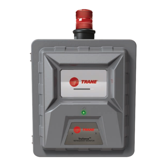
Installation, Operation, and Maintenance
TruSense™ Refrigerant Monitor
Model:
RMWH
Only qualified personnel should install and service the equipment. The installation, starting up, and servicing of
heating, ventilating, and air-conditioning equipment can be hazardous and requires specific knowledge and training.
Improperly installed, adjusted or altered equipment by an unqualified person could result in death or serious injury.
When working on the equipment, observe all precautions in the literature and on the tags, stickers, and labels that are
attached to the equipment.
August 2020
SAFETY WARNING
RMWH-SVX001C-EN
Advertisement
Table of Contents

Related Manuals for Trane TruSense RMWH


Summary of Contents for Trane TruSense RMWH
- Page 1 Installation, Operation, and Maintenance TruSense™ Refrigerant Monitor Model: RMWH SAFETY WARNING Only qualified personnel should install and service the equipment. The installation, starting up, and servicing of heating, ventilating, and air-conditioning equipment can be hazardous and requires specific knowledge and training. Improperly installed, adjusted or altered equipment by an unqualified person could result in death or serious injury.
- Page 2 (Global Harmonized System of Classification and compounds have the same potential impact to the Labeling of Chemicals) guidelines for information on environment. Trane advocates the responsible handling of allowable personal exposure levels, proper all refrigerants-including industry replacements for CFCs respiratory protection and handling instructions.
- Page 3 Copyright This document and the information in it are the property of Trane, and may not be used or reproduced in whole or in part without written permission. Trane reserves the right to revise this publication at any time, and to make changes to its content without obligation to notify any person of such revision or change.
-
Page 4: Table Of Contents
Table of Contents General Information Span Gas Calibration ..... 6 ....27 Unsuccessful Calibrations . - Page 5 ......57 Appendix D: MODBUS Holding Registers . 58 TruSense RMWH Refrigerant Monitor—MOD- BUS RTU (Holding Registers) ..58 RESET Button Actions .
-
Page 6: General Information
Refrigerant Monitor system to a safe area. Improper Note: For any maintenance procedure provided in this venting of the exhaust can cause serious personal injury or manual, use only genuine Trane replacement parts. death. Refer to “Exhaust Venting,” p. Repair or alteration of the TruSense™ RMWH... -
Page 7: Description
When the device is installed, operated, and maintained according to Trane’s recommendations, it provides reliable protection and long-term stability. 1. Mounting locations (10 in. x 14-5/8 in.) - Page 8 Description Figure 3. Right side of device Figure 4. Left side of device 1. AC power wiring cutout 1. Latches (lockable with padlock) 2. Protective earth grounding cutout (optional) 2. Signal wiring cutouts 3. Relay wiring cutout 4. Approval and unit identification label Figure 5.
-
Page 9: Visible Alarming Devices
Description Figure 6. Internal touchpoints 1. Fuses Optional External Horn 2. AC wiring cover An optional external horn can be mounted in a location 3. Internal filters away from the device to provide an audible indicator of a gas leak. 4. -
Page 10: Analog Communication
Description For a list of the registers that are available for exchange Table 3. 0–10 Vdc with the MODBUS® controller, refer to “Appendix D: MODBUS Holding Registers,” p. For a list of the BACnet® Objects that are available for Sample Line 4 or 8 pt system 16 pt system exchange with the BACnet®... -
Page 11: Installation
Remote horn (if equipped) e. Protective foam 4. Notify Trane of any shortages immediately. 5. Keep the original packaging in case it is necessary to return the device for service. 6. Release the two latches on the left side of the device. -
Page 12: Sample And Exhaust Lines
Note: Use the appropriate tools to give a clean, smooth end to the tubing when it is cut. Routing and Placement Trane recommends the use of at least two gas-monitoring points per chiller for sufficient detection monitoring. Due to installation and application variations, each system must be analyzed individually. -
Page 13: End-Of-Line Filters
“Tubing Material,” p. For installations where water condensation in the sample Do the following procedure to connect the sample and lines is likely, Trane recommends installing a water trap exhaust lines: filter such as a Parker P/N F504-01AHX67 or equivalent. - Page 14 Installation • To achieve this connection, install a 10 AWG or larger The TruSense™ RMWH Refrigerant Monitor Wiring copper wire between the grounding lug terminal strip Diagram (Figure 11) gives the details of the wiring on the right side of the TruSense™ RMWH Refrigerant requirements for the device.
-
Page 15: Electrical Power Supply Requirements
Installation Electrical Power Supply 5. Open the enclosure. 6. Attach the ESD wrist strap to the ESD connection point Requirements inside the enclosure. 7. Use a 1/4-in. hex driver to remove the four hex nuts on the circuit board cover. WARNING 8. -
Page 16: Initial Setup
Initial Setup WARNING Risk of Asphyxiation! Failure to follow instructions below could cause inaccurate readings and improper gas monitoring which could result in death or serious injury. Make sure to remove the cap from the exhaust port before operating the device. 3. - Page 17 Initial Setup 6. Select the Hour/Minute fields, and use the alphanumeric keypad pop-up to enter values. Select to accept the values. 10. Select Next. If password protection is enabled, the Password Required pop-up will show when any user tries to change an editable screen.
-
Page 18: Point Configuration
Initial Setup Point Configuration 8. The Initial Setup screen shows a check mark beside the Point Configuration step to indicate that it is complete. Select Continue to go to the gas Note: At initial setup, all points except Point 1 are configuration setup. -
Page 19: Gas Configuration
Initial Setup Gas Configuration 4. Select the Edit button for Caution, Warning, or Alarm, as applicable. 1. On the Select Gas screen, select an empty gas slot. Note: If the Setpoints tab is selected but a gas has not been selected, the options on the Note: A maximum of six slots or gases can be Configure Gas screen will be inactive. - Page 20 Initial Setup 9. Select Done to accept the settings and return to the 14. Repeat Step 1 through Step 13 for each gas to be gas-specific configuration screen, which shows the configured. updated settings. Note: The Reset tab is not used during the initial setup.
-
Page 21: Relay Configuration
Initial Setup Relay Configuration 4. Do the following to test the relay: a. Select ON. Each relay is mapped to a specific predetermined function; b. Make sure the equipment connected to the relay that is, fault, alarm, warning, caution, or horn. operates as expected. -
Page 22: Communications Output
Initial Setup Communications Output 4. If BACnet is selected, do the following: a. Select Edit. There are three options available to support digital outputs. For a list of the registers that are available for exchange with the MODBUS® controller, refer to “Appendix D: MODBUS Holding Registers,”... - Page 23 Initial Setup 8. The Initial Setup screen shows that all initial setup steps are complete. Select Finished to confirm the configuration settings and move to the Initial Calibration screen. RMWH-SVX001C-EN...
-
Page 24: Calibration
Calibration Figure 12. Calibration curve WARNING Risk of Asphyxiation! Failure to follow instructions below could cause inaccurate readings and improper gas monitoring which could result in death or serious injury. • Make sure the device has been receiving power for at least 2 hours before performing a calibration. -
Page 25: Initial Setup
Calibration Initial Setup Routine Operation Following the initial setup, an initial calibration must be completed to ensure sensor accuracy. WARNING For a description of the dashboard, refer to “Dashboard Risk of Asphyxiation! Overview,” p. Failure to follow instructions below could cause 1. -
Page 26: Stopping Calibration
Calibration Stopping Calibration Zero Gas Calibration During some phases, when Cancel is available in the top 1. Connect the zero-gas scrubber tubing to the calibration left corner, the calibration process can be stopped. port. 1. To stop the calibration process, select Cancel. 2. -
Page 27: Span Gas Calibration
Span Gas Calibration 4. On the Calibration Complete screen, do one of the following: Note: To prevent zero-gas contamination, Trane a. To continue with span gas calibration, select Span recommends using different regulators to do zero Gas Calibration. Go to Step 1 “Span Gas... - Page 28 Calibration 10. On the Span Gas Calibration screen, select Start. 14. On the Set Reminder screen, select the applicable button for the calibration interval. At the selected interval, a pop-up will signal the need for calibration. 15. Select Next. A progress bar shows during the span gas calibration. 16.
-
Page 29: Unsuccessful Calibrations
Calibration Unsuccessful Calibrations If Close is selected, on the dashboard, a gray check mark indentifies the points that are affected by the unsuccessful calibration. The gas readings for these In the unlikely event that a problem occurs during a sample points are below the alarm threshold but may calibration process, the Results screen will show the not be completely accurate. -
Page 30: Routine Operation
Routine Operation Point Details WARNING To see details about a specific point, on the dashboard, Risk of Asphyxiation! select the point tile. A detail pop-up opens. Failure to follow instructions below could cause To close the detail pop-up and return to the dashboard, inaccurate readings and improper gas monitoring select the X at the top right corner. -
Page 31: Predictive Warnings
Routine Operation Note: The Hold feature can only be applied to one point Acknowledging the predictive warning triggers a at a time. During the hold duration for the selected notification that shows on the Diagnostics button on the point, the Hold button is inactive for all other dashboard. -
Page 32: Non-Latching Events
Routine Operation Non-Latching Events Select Reset to resolve the event and return to the dashboard. The point tile on the dashboard shows in its Non-latching events do not require user interaction for normal state, and the event is considered resolved. resolution. -
Page 33: Critical Faults
Routine Operation If multiple faults occur simultaneously, the pop-up shows • The device cannot monitor for gas. the faults as line items. • The 4–20 mA output decreases to the user-specified To acknowledge the event and return to the dashboard, fault level. -
Page 34: Alarms
Routine Operation In the Event Log, events are color coded by type: The last 100 events show in chronological order. When there are 100 events in the list and a new event occurs, the • Red = Caution, Warning, Alarm oldest event is deleted to make space for the new event to •... -
Page 35: Edit Settings
During routine operation, the For help with forgotten passwords or password resets, screen headers show the buttons. contact local Trane Customer Service. To adjust the settings for the language, date and time, and password, go to “Initial Setup,” p. -
Page 36: Gas Configuration
Routine Operation Gas Configuration If the button is selected while the Busy message shows, a pop-up asks whether to abandon Use the Gas option to change the gas configuration the configuration changes. settings. • To return to the Gas screen without saving the Note: Except for the buttons that show in the screen configuration changes, select Return without headers, the screens and steps used to change the... -
Page 37: Point Configuration
Routine Operation Note: If only one gas slot is configured, it cannot be Note: When a change is made to the configuration, deleted. At least one gas slot must be the Save button becomes active. configured for the system to function. If an attempt is made to delete the only configured gas slot, a warning pop-up indicates that the action cannot be completed. -
Page 38: Relay Configuration
Routine Operation Reset Tab Relay Configuration Use the Reset tab to reset the point name and disable the Use the Relay option to change the relay configuration point. settings or test a relay. 1. On the Point Configuration: Point # screen, select Note: Except for the buttons that show in the screen the Reset tab. -
Page 39: Communications Output
Routine Operation If the button is selected while the Busy While the configuration is being updated, a Busy message message shows, a pop-up asks whether to abandon the shows at the bottom of the Outputs screen. configuration changes. • To return to the Configure Relays screen without saving the changes, select Return without Saving. - Page 40 Routine Operation Use the scroll bar to see all of the available information. RMWH-SVX001C-EN...
-
Page 41: Diagnostics
Diagnostics If the date setting is changed after the initial set up To see a detailed graph of the flow data for a point over configuration, the predictive maintenance logs will need time, select the point tile. to be reset on each graph to ensure accuracy. When a predictive warning, fault, or alarm is acknowledged, a notification shows on the Diagnostics button on the dashboard. -
Page 42: Sensor Performance
Diagnostics Values below the alarm threshold show in red. To see details about sensor performance, select the text box. To reset the flow diagnostics baseline, select Reset. The bottom left and top right quadrants show In the Warning pop-up, select Reset to continue the predictive warnings in yellow. -
Page 43: Pump Performance
Diagnostics To see details about sensor performance in this The Pump Performance screen shows a graph that quadrant, select the text box. plots pump performance over time. To see details about pump performance, select the text box. To reset the sensor performance baseline, select Reset. -
Page 44: Errors
Diagnostics Errors The region of the graph that is below the predictive warning threshold shows in yellow or red, depending on the severity of the performance degradation. To see details Errors are events that do not result in a fault condition but about pump performance, select the text box. - Page 45 Diagnostics To see details about an error, select it. RMWH-SVX001C-EN...
-
Page 46: Maintenance
Maintenance Obey the following warnings and cautions for all If an end-of-line filter becomes severely clogged with maintenance procedures. particulates, the flow rate for that sample line will decrease and eventually cause a flow rate fault. NOTICE Do the following procedure to replace an end-of-line filter: Electrostatic Discharge! 1. -
Page 47: Examine And Replace Internal Inline Filters
Maintenance Examine and Replace Internal Inline Filters Inline filters are installed inside the device enclosure (refer to the following figure). Figure 13. Location of inline filters Periodically examine the inline filters inside the device 7. Discard the dirty filter. enclosure for dirt and particulate buildup. 8. -
Page 48: Replace Fuses
6. Turn the top of the fuse holder counterclockwise and remove it. 7. Remove the defective fuse. 8. Install a new fuse. Only use Trane P/N FUS02537 or an equivalent certified fuse. 9. Install the fuse holder and turn the top clockwise to secure it. -
Page 49: Cleaning
Cleaning Touchscreen Display NOTICE Equipment Damage! Use of improper cleaning materials can result in optical impairment of the display and/or damage to the device. Use a soft lint-free cloth. The cloth can be dry or lightly dampened with a mild detergent. The detergent must have neutral pH. -
Page 50: Technical Data
Technical Data Technical Specifications/ Equipment Ratings Usage Indoor use only Overvoltage Category II Pollution Degree 2 100–240 Vac, 50/60 Hz, 200 VA maximum AC Power Supply voltage not to fluctuate more than ±10% Operating Temperature 32°F–122°F (0°C to 50°C) Operating Altitude Limit 9762 ft (2975 m) Operating Humidity 0 to 95%, noncondensing... -
Page 51: Troubleshooting Guidelines
“Communications Output,” p. WARNING 2. Make sure the wire connections are correct. Hazardous Voltage! 3. Contact Trane Customer Service. Failure to disconnect power before servicing could result in death or serious injury. Disconnect all electric power, including remote disconnects before servicing. Follow proper lockout/ tagout procedures to ensure the power cannot be inadvertently energized. -
Page 52: Ordering Information
Ordering Information To obtain replacement parts, please contact your local Trane Parts and Supply store or visit www.tranesupply.com. Replacement Parts WARNING Refrigerant Gas Leak! Refrigerant or other gases could displace available oxygen to breathe, causing possible asphyxiation or other serious health risks. Some gases may be flammable and or explosive. - Page 53 Ordering Information Figure 15. Replacement parts identifier TRANE PART NUMBER PART DESCRIPTION Replacement Parts FLR04743 END OF LINE FILTER PACK OF 4 FLR01881 INLINE FILTER FUS02537 2.0 AMP, 250 V Fuse KIT18294 PHOENIX TERMINAL KIT LIT0882 RED STROBE Installation and Calibration TUB10602 TUBE;...
-
Page 54: Appendix A: Startup Check List
Appendix A: Startup Check List Before applying power to the TruSense™ RMWH Refrigerant Monitor, check for all items in the following table: Examiner’s Item Check for Initials Proper mounting: Indoors on a rigid surface that does not have vibration or mechanical shock In a vertical position approximately 5 ft (1.5 m) off the ground Away from direct solar heating or other excessive heat sources, wet or damp conditions where condensation can occur, areas that are dirty or exposed to oils or chemicals, areas where explosive concentrations of combustible... -
Page 55: Appendix B: Installation Of Optional Equipment
Appendix B: Installation of Optional Equipment 6. Use a 1/4-in. hex driver to remove the four hex nuts on NOTICE the circuit board cover. Electrostatic Discharge! 7. Remove the circuit board cover. 8. Remove the hole plug out of the top of the device. Electrostatic discharge can short equipment circuitry.... -
Page 56: External Alarm Activation Station
Appendix B: Installation of Optional Equipment 7. Use a ¼-in. hex driver to remove the four hex nuts on 9. Disconnect the ESD wrist strap from the ESD the circuit board cover. connection point inside the enclosure. 8. Remove the circuit board cover. 10. -
Page 57: Appendix C: Default Settings
Appendix C: Default Settings Alarm Setpoints The default settings for the alarm setpoints are the following: • 5, 20, and 50 percent of full-scale range, except for R123, which are 1, 2, and 5 percent of full-scale range • Non-latching •... -
Page 58: Appendix D: Modbus Holding Registers
Appendix D: MODBUS Holding Registers TruSense RMWH Refrigerant Monitor—MODBUS RTU (Holding Registers) Section Register Name Channel # Index Property Notes Product ID 40001 Read “CG” Firmware Version 1 40002 Read Major(MSB:1b)/Minor(1b) Firmware Version 2 40003 Read Build(2b) Reserved 4 40004... - Page 59 Appendix D: MODBUS Holding Registers Section Register Name Channel # Index Property Notes 9 Gas Number 40042 Read Refer to “Gas Types,” p. 61 9 Gas Conc. 40043 Read Channel 9 9 Status 40044 Read Refer to “Channel Status Flags,” p. 61 9 Reserved 40045 Read...
-
Page 60: Reset Button Actions
Appendix D: MODBUS Holding Registers Section Register Name Channel # Index Property Notes Next Cal Time 40090 Read In days from 1970 Zero Cal Time 40091 Read In days from 1970 Span Cal Time #00 40092 Read In days from 1970 – R-11 Span Cal Time #01 40093 Read... -
Page 61: Channel Status Flags
Appendix D: MODBUS Holding Registers Channel Status Flags Description 0x0001 Caution Set if caution level is achieved 0x0002 Warning Set if warning level is achieved 0x0004 Alarm Set if alarm level is achieved 0x0008 Beacon Set if C/W/A is set 0x0010 Horn Set if any configured C/W/A is set and not acknowledged yet... -
Page 62: Appendix E: Bacnet Objects
Appendix E: BACnet Objects TruSense RMWH Refrigerant Monitor—BACnet Section Object Name Channel # Object Type Inst # Property Notes Product ID Analog Input Read “CG” Firmware Version Analog Input Read Build(MSB:2b)/Major(1b)/Minor(1b) Reserved 4 Analog Input Read Reserved 5 Analog Input... - Page 63 Appendix E: BACnet Objects Section Object Name Channel # Object Type Inst # Property Notes 10 Gas Number Analog Input Read Refer to “Gas Types,” p. 65 10 Gas Conc. Analog Input Read Channel 10 10 Status Analog Input Read Refer to “Channel Status Flags,”...
-
Page 64: Reset Button Actions
Appendix E: BACnet Objects Section Object Name Channel # Object Type Inst # Property Notes Next Cal Time Analog Input Read In days from 1970 Zero Cal Time Analog Input Read In days from 1970 Span Cal Time #00 Analog Input Read In days from 1970 –... -
Page 65: Channel Status Flags
Appendix E: BACnet Objects Channel Status Flags Description 0x0001 Caution Set if caution level is achieved 0x0002 Warning Set if warning level is achieved 0x0004 Alarm Set if alarm level is achieved 0x0008 Beacon Set if C/W/A is set 0x0010 Horn Set if any configured C/W/A is set and not acknowledged yet 0x0020... - Page 68 For more information, please visit trane.com or tranetechnologies.com. Trane has a policy of continuous product and product data improvement and reserves the right to change design and specifications without notice. We are committed to using environmentally conscious print practices.
Need help?
Do you have a question about the TruSense RMWH and is the answer not in the manual?
Questions and answers