Trane Tracer TD7 Installation, Operation And Maintenance Manual
For the tracer uc600 programmable controller
Hide thumbs
Also See for Tracer TD7:
- User manual (32 pages) ,
- Manual (24 pages) ,
- User manual (24 pages)
Table of Contents
Advertisement
Installation, Operation, and Maintenance
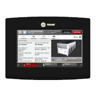
Tracer®TD7 Display
for the Tracer UC600 Programmable
Controller
Only qualified personnel should install and service the equipment. The installation, starting up, and servicing of
heating, ventilating, and air-conditioning equipment can be hazardous and requires specific knowledge and training.
Improperly installed, adjusted or altered equipment by an unqualified person could result in death or serious injury.
When working on the equipment, observe all precautions in the literature and on the tags, stickers, and labels that are
attached to the equipment.
April 2020
SAFETY WARNING
BAS-SVX50F-EN
Advertisement
Table of Contents

Related Manuals for Trane Tracer TD7


Summary of Contents for Trane Tracer TD7
- Page 1 Installation, Operation, and Maintenance Tracer®TD7 Display for the Tracer UC600 Programmable Controller SAFETY WARNING Only qualified personnel should install and service the equipment. The installation, starting up, and servicing of heating, ventilating, and air-conditioning equipment can be hazardous and requires specific knowledge and training. Improperly installed, adjusted or altered equipment by an unqualified person could result in death or serious injury.
- Page 2 OSHA, NFPA 70E, or other country-specific requirements for arc flash protection, PRIOR to servicing the unit. NEVER PERFORM ANY SWITCHING, DISCONNECTING, OR VOLTAGE TESTING WITHOUT PROPER ELECTRICAL PPE AND ARC FLASH CLOTHING. ENSURE ELECTRICAL METERS AND EQUIPMENT ARE PROPERLY RATED FOR INTENDED VOLTAGE. ©2020 Trane BAS-SVX50F-EN...
- Page 3 Introduction Copyright This document and the information in it are the property of Trane, and may not be used or reproduced in whole or in part without written permission. Trane reserves the right to revise this publication at any time, and to make changes to its content without obligation to notify any person of such revision or change.
-
Page 4: Table Of Contents
Installing the Tracer TD7 Display ........ - Page 5 Table of Contents Custom Reports ..........28 Creating a Custom Report .
- Page 6 Table of Contents Troubleshooting ..........66 Identifying and Diagnosing Issues .
-
Page 7: Introduction
12, for more information. AC Power The Tracer TD7 display is powered by 24 VAC and requires 21 VA power, which it receives through a power cable. The display is typically connected to one of the two available 24 VAC outputs on the Tracer UC600 but can be powered from an alternate power source. -
Page 8: Dimensions
Introduction Dimensions 7.9 in. (200.7 mm) 8.3 in. (211.6 mm) 2.1 in. (53.2 mm) 1.7 in. (41.9 mm) 5.5 in. (139.9 mm) 6.3 in. (158.8 mm) Note: The power cable is permanently attached to the TD7 display. The power connector provides strain relief and protection from the elements. -
Page 9: Specifications And Agency Compliance
Introduction Specifications and Agency Compliance Specification Input power: 24 Vac +/- 15%, 21 VA, 50 or 60 Hz -67°F to 203°F (-55°C to 95°C) Storage temperature: Humidity: Between 5% and 100% (non-condensing) Temperature: -40°F to 158°F (-40°C to 70°C) Operating temperature: Humidity: Between 5% and 100% (non-condensing) Mounting surface must support 1.625 lb (0.737 kg) ... -
Page 10: Screen Overview
Top display area • Main display area • Bottom display area Figure 1. Tracer TD7 display screen Top display area Main display area Bottom display area Top Display Area The Back button, when touched, returns to the previous screen visited. -
Page 11: Bottom Display Area
Introduction Bottom Display Area The bottom display area contains functional buttons that provide a link to the appropriate screen. Screen brightness settings: Touch this icon to open the brightness screen. Touch this button to open the Alarms screen. When an alarm is present, this button will flash red. -
Page 12: Installing The Tracer Td7 Display
Failure to disconnect power before servicing could result in death or serious injury. Packaged Contents • One (1) Tracer TD7 display with permanently attached 3.3 ft (1.0 m.) power cable with male connector (PN: X13760335-01) • Four (4) M-4 screws •... -
Page 13: Installing The Td7 Display In A Trane Large Enclosure
Installing the TD7 Display in a Trane Large Enclosure Important: The enclosure door must be installed on the large enclosure prior to installing the TD7 display. Order numbers for the Trane Large enclosure (display-capable door) are: • X13651553010 (120 VAC) •... - Page 14 Installing the Tracer TD7 Display 7. Snip off the blue and gray wires from the power cable with female connector (PN: X19051625020) so only the red and black wires remain. 8. Place one of the supplied terminal blocks onto an available 24 VAC terminal connection on the UC600.
-
Page 15: Installing The Td7 Display Onto A Vesa Mounting Bracket
Installing the TD7 Display onto a VESA Mounting Bracket The Tracer TD7 can be mounted near the UC600 with the supplied Ethernet cable and power cable, or remotely mounted up to 328 ft (100 m.) by using a field-suppled 75 mm VESA mount. - Page 16 Installing the Tracer TD7 Display Figure 4. Example VESA mounting Note: The swing arm style shown above is only for illustration purposes. Compatible brackets must be ordered separately. Order from Trane the VESA mounting bracket, Part Number X05010511010 (flush) or brackets from other suppliers.
-
Page 17: Setting Up And Using The Td7 Display Portable Carry Case
Installing the Tracer TD7 Display Setting Up and Using the TD7 Display Portable Carry Case The TD7 Display Portable Carry Case (PN: X18210613010) is recommended when a TD7 display will be used on more then one Tracer UC600. The case protects the TD7 display when not in use, stores the power and Ethernet cables, and is equipped with a handle to carry the display. -
Page 18: Using The Td7 Portable Display
Powering up the TD7 Display for the First Time After completing the installation instructions in “Installing the Tracer TD7 Display,” p. 12, The TD7 display can be powered up. Before applying power to the TD7, verify the following: •... -
Page 19: Alarms
Alarms Alarms appear on the Tracer TD7 display immediately upon detection. Touch the Alarms button in the bottom display area to view the Alarms screen. Active Alarms Figure 6 shows the Active Alarms screen and commonly used functions. Configuration is not required in order for points in alarm to appear in the Active Alarms screen. -
Page 20: Viewing Active And All Alarms
Alarms Figure 7. All Alarms screen Number of All Alarms Sortable Columns Alarm Severity All Alarms Button Viewing Active and All Alarms • Active alarms: These are alarms that require attention. All alarms that are currently active appear when you view this category. Active alarms are not reset by way of the display. Active alarms will clear automatically when the condition causing the alarm is removed. -
Page 21: Alarm Icons
Alarms Alarm Icons Alarms icons appear in the left-most column of the alarms screen. They are identifiable by their shape and color. Table 1. Alarm icons Active Alarm Icons Notification Class Critical Service Required Warning Information None Note: Notifications classes are configured in point alarm settings section in Tracer TU. Sorting Alarms To sort alarms by a category other than date and time, touch one of the other column headings in the table. -
Page 22: Overrides
Overrides Overrides can be performed at priority level 8 using the Tracer TD7. Only overrides at priority level 8 Manual Operator can be created or released from the TD7 display. User overrides are defined as points that are controlled at: 1 Manual Life safety, 8 Manual Operator (display priority), 11 User medium, and 13 User low. -
Page 23: Binary Overrides
Overrides Temporary Override Area This area allows you to set up a temporary override. See “Setting Up a Temporary Override,” p. Action Area This area allows you to apply, save, or cancel edits made to the point override. Releasing an Override Touch the Release Override button to release the current override. -
Page 24: Analog Overrides
Overrides Figure 10. Multistate override screen (five or more states) Analog Overrides The Analog Override screen contains up and down arrows in the Override setting area, as well as a keypad icon that when touched, opens the Analog Keypad. Use the up and down arrow buttons to select a value. Touch the Apply or Save button to retain your changes. -
Page 25: Setting Up A Temporary Override
Overrides Setting Up a Temporary Override You can set up a temporary override by using the buttons in the Temporary Override area. The default for temporary overrides is 2 hours 0 minutes. The maximum duration for a temporary override is 99 hours 59 minutes. If more time is needed, consider setting up a permanent override. 1. -
Page 26: Reports
Reports You can use the Tracer TD7 Display to view a variety of reports and create and edit custom reports. Touch the Reports button in the bottom display area to view the Reports screen. The Reports screen contains the following buttons: •... -
Page 27: Accessing A Graphic
Reports Accessing a Graphic 1. Navigate to the Reports screen, then touch Custom Graphics. The Custom Graphics screen appears (Figure 13). Each button on the screen represents a custom graphic. Custom graphics are published to the UC600 using Tracer Graphics Editor (TGE) in Tracer TU (Version 8.1 or higher). -
Page 28: Custom Reports
Custom Reports You can create up to three custom reports using the Tracer TD7 Display or the Tracer TU service tool. Reports may contain all nine point types. A maximum of 36 pieces of data is allowed per custom report. -
Page 29: Editing A Custom Report
Reports Figure 16. New custom report screen Editing a Custom Report 1. Touch Reports to view the Reports screen. 2. Touch the report that you want to edit. Follow steps 2 through 4 in “Creating a Custom Report,” p. 28. to complete your edits. Figure 17. -
Page 30: Override Summary
Reports 2. Use the arrow buttons to locate the item to be reordered. When located, touch the item which will then be highlighted blue (see Figure 17). 3. Use the arrow buttons to move the highlighted item to the top of the list (number 1 position). 4. -
Page 31: All Points Report
Reports Figure 19. Override summary screen All Points Report Touch the All Points Report button to view the All Points Report screen, which contains all configured points for the unit controller. Use the up and down arrows located at the right most bottom of the screen to page up or down. -
Page 32: About
Reports About Touch the About button to view the About screen. View information about the unit controller and the TD7 display to which it is connected. Touch the arrow button to scroll to the next screen. Figure 21. About screen Controller Name This is the name that was assigned to the UC600 in Tracer TU. -
Page 33: Expansion Modules
Reports Controller Build Part Number This is the firmware version that is currently running on the controller. Firmware is similar to an operating system on a PC. Controller Backup Firmware The firmware that runs when the controller is in service mode. The primary function of this firmware is to provide a minimal boot of the controller so that a new controller build can be loaded on the controller should it be necessary. -
Page 34: Tgp2 Programs
Reports TGP2 Programs Touch the TGP2 Programs button to view the TGP2 Programs screen. All TGP2 programs that have been installed on the controller appear here. The program name, status, run type, and interval for each program is provided. Interval is the scheduled run interval for the program and is displayed in HH:MM:SS. -
Page 35: Overrides
Overrides Overrides can be performed at priority level 8 using the Tracer TD7. Only overrides at priority level 8 Manual Operator can be created or released from the TD7 display. User overrides are defined as points that are controlled at: 1 Manual Life safety, 8 Manual Operator (display priority), 11 User medium, and 13 User low. -
Page 36: Binary Overrides
Overrides Temporary Override Area This area allows you to set up a temporary override. See “Setting Up a Temporary Override,” p. Action Area This area allows you to apply, save, or cancel edits made to the point override. Releasing an Override Touch the Release Override button to release the current override. -
Page 37: Analog Overrides
Overrides Figure 26. Multistate override screen (five or more states) Analog Overrides The Analog Override screen contains up and down arrows in the Override setting area, as well as a keypad icon that when touched, opens the Analog Keypad. Use the up and down arrow buttons to select a value. Touch the Apply or Save button to retain your changes. -
Page 38: Setting Up A Temporary Override
Overrides Setting Up a Temporary Override You can set up a temporary override by using the buttons in the Temporary Override area. The default for temporary overrides is 2 hours 0 minutes. The maximum duration for a temporary override is 99 hours 59 minutes. If more time is needed, consider setting up a permanent override. 1. -
Page 39: Data Graphs
Data Graphs Data graphs allow users to view trend logs from the Tracer UC600 controller in graphical format on the TD7 Display. Up to eight data graphs can be created with a maximum of four data logs per graph. Data graphs are user-defined and can be edited by changing the scale on the left and right Y-axis and choosing the line color. - Page 40 Data Graphs Figure 29. Edit Data Graph screen 5. Touch the Add/Remove button to add values to the custom data graph. The Add/Remove screen appears. 6. Use the arrow buttons to select a datalog type: analog, binary, or multistate, which then populates the box directly below (Figure 30).
- Page 41 Data Graphs 9. Use the Edit Data Graph screen to modify the data graph. Touch the Edit button that corresponds with the value that you want to change. Only one value can be edited at a time. Figure 31. Edit Data Graph screen (after values have been added) 10.
- Page 42 Data Graphs 9. Touch the View Data Graph button to display the new graph (Figure 33). Note: Depending on the sampling rate, the custom data graph may be empty for several hours. You can make changes to the way data is presented on the graph at anytime. Touch the zoom-in icon and zoom-out icon to either increase or decrease the viewable time frame.
- Page 43 Data Graphs Figure 34. Repeat steps 2 through 4 until all preferred changes have been made. Editing the Y- Axis BAS-SVX50F-EN...
-
Page 44: Settings
Touch the Schedules button to open the Schedules screen. The UC600 supports up to three schedules that can be created, view, and edited on the Tracer TD7 Display, at any given time. These include analog, binary, or multistate (HVAC scheduling is not currently supported). See “Setting Up... - Page 45 Settings Figure 36. Display Preferences screen Date Format Touch the Date Format button to open the associated screen. Three options are available to display the current date: MMDDYYYY, DDMMYYYY, and YYYYMMDD. Date Separator Touch the Date Separator button to open the associated screen. Three options are available to display separators in the date format: None, Hyphen (-), or Slash (/).
- Page 46 Settings Header Data Point Use the arrow button on the Display Preferences screen to advance to page 2. Touch the Header Data Point button to open the associated screen. The Header Data Point appears in the top right display area on all screens. Use the arrow buttons to scroll through the points. Click Add to move the highlighted point to the right side of the screen(Figure 37, p.
- Page 47 Settings Figure 38. Home Page screen Standard Report Custom Graphics Reports Standard Report Alarms/Historic Alarms BAS-SVX50F-EN...
-
Page 48: Language
Settings Language Touch the Language button, or the language icon ( ) located at the bottom right of each screen, to open the open the Language screen. Twenty-five languages are available and represented on the selection buttons. Select a language that you want displayed on each TD7 screen and then touch Save. -
Page 49: Clean Touchscreen
Settings Clean Touchscreen Touch the Clean Touchscreen button to safely clean the TD7 touchscreen using any brand of common household glass cleaner. When this button is touched, the screen background color becomes black, allowing dirt and fingerprints to become more visible. It also displays a countdown timer (five to zero seconds).Touch the screen anytime within the 5-second countdown to begin cleaning the screen (each touch resets the 5-second countdown). -
Page 50: Log Out
Settings Figure 42. TD7 PIN entry screen Log Out To log out of the TD7, press the Log Out button on the Settings Screen (Figure 43.) Note: Users are automatically logged out of the TD7 when the TD7 backlight has timed out. See “Backlight Timeout,”... -
Page 51: Setting Up And Maintaining Schedules
Settings Setting Up and Maintaining Schedules Tracer TD7 supports three types of schedules: analog, binary, and multistate. A maximum of three schedules can be created. Each schedule can contain up to 10 members, 10 events, and 25 exceptions. Schedules are created on a series of “events” that occur on each day of the week. An event is a change in a value at a specific time that can occur during any day of the week. - Page 52 Settings Figure 45. Creating a new schedule Touch the Edit Schedule button, which opens the Edit Schedule screen. Then touch the Edit Members button. 4. Use the arrow buttons to select a point type to be scheduled: analog, binary, or multistate. 5.
- Page 53 Settings Touching the Save button causes the TD7 to create the schedule, which renders the display as temporarily unavailable during the update (Figure 47). Figure 47. Updating data message 7. After the update is complete, the schedule landing screen appears. Select the schedule you just created to view the schedule (Figure 48).
-
Page 54: Setting Schedule Defaults And Adding Events
Settings Setting Schedule Defaults and Adding Events After creating a schedule and selecting the members, the next step is to set schedule defaults and add weekly events. An event is defined as a time-value pair. To access the daily view screen, touch the day of the week inside of the schedule in which you want to add events. - Page 55 Settings Figure 50. Editing the default value 11. From the Edit Schedule screen, touch the Events button. The Events screen opens (Figure 51). Touch any button on the bottom of the Events screen to view the normal events that occur on the selected day.
-
Page 56: Adding Exceptions To A Schedule
Each exception can also contain up to ten (10) of its own events. The Tracer TD7 can support up to 25 exceptions in a single schedule. However, it is not recommended to place more than one exception on a single day. - Page 57 Settings There are three different options for applying an exception to a schedule: • Does not Recur — select this option for an exception that will be used for a single occurrence. • Monthly — select this option to apply an exception that will occur regularly each month. For example, the third Tuesday of each month a PTA meeting is scheduled until 7:00 pm.
- Page 58 Settings Figure 55. Edit Recurrence screen (Add Exception) 4. Using the buttons and arrow controls, determine when the exception is to occur. Touch the Save button. The Exception screen displays, which contains the newly created exception (Figure 56). Figure 56. Exceptions added (no events) Touch to remove an exception Touch to add an...
- Page 59 Settings Figure 57. Adding events to an exception 3. Continue to add your preferred events until the exception matches the desired outcome (Figure 58). Figure 58. Schedule Exceptions (with defined exceptions) Removing Exceptions 1. To remove recurring exceptions that never expire, navigate to the schedule from which you want to remove exceptions.
- Page 60 Settings A confirmation dialog box appears (Figure 59). 4. Touch the Yes button. Figure 59. Removing exceptions Clearing Expired Exceptions 1. Navigate to the schedule from which you want to clear expired exceptions. 2. Touch the Edit Schedule button. 3. Touch the Clear Expired Exceptions button on the Edit Schedule screen (Figure 49, p.
-
Page 61: Viewing The Schedule
Settings Viewing the Schedule After creating a weekly schedule, adding events, and applying exceptions, the resulting schedule can be viewed (Figure 61) at anytime by touching Settings > Schedules, then select a schedule. Touching an event in the This Week screen will navigate you to the Add Events screen for the selected day. -
Page 62: Overrides
Overrides Overrides can be performed at priority level 8 using the Tracer TD7. Only overrides at priority level 8 Manual Operator can be created or released from the TD7 display. User overrides are defined as points that are controlled at: 1 Manual Life safety, 8 Manual Operator (display priority), 11 User medium, and 13 User low. -
Page 63: Binary Overrides
Overrides Temporary Override Area This area allows you to set up a temporary override. See “Setting Up a Temporary Override,” p. Action Area This area allows you to apply, save, or cancel edits made to the point override. Releasing an Override Touch the Release Override button to release the current override. -
Page 64: Analog Overrides
Overrides Figure 65. Multistate override screen (five or more states) Analog Overrides The Analog Override screen contains up and down arrows in the Override setting area, as well as a keypad icon that when touched, opens the Analog Keypad. Use the up and down arrow buttons to select a value. Touch the Apply or Save button to retain your changes. -
Page 65: Setting Up A Temporary Override
Overrides Setting Up a Temporary Override You can set up a temporary override by using the buttons in the Temporary Override area. The default for temporary overrides is 2 hours 0 minutes. The maximum duration for a temporary override is 99 hours 59 minutes. If more time is needed, consider setting up a permanent override. 1. - Page 66 Troubleshooting This section describes the possible error messages and other issues that you may encounter while using the Tracer TD7 display. Identifying and Diagnosing Issues Problem Possible Cause Possible Solution Blank display (TD7 does not respond Verify that the TD7 is connected to a power source, No power.
- Page 67 Troubleshooting Figure 67. Automatic rediscover and automatic restart messages Automatic rediscover: This message appears when data is being updated. Automatic restart: This message appears whenever a user is added or deleted. BAS-SVX50F-EN...
- Page 68 The Choose the Files Affected dialog box appears. NOTICE: Equipment Damage! Do not power down the Tracer UC600, the Tracer TD7, or remove the USB cable during file download. Doing so will damage the Tracer TD7. Figure 68. Selected Devices dialog box (choose TD7) 6.
- Page 72 For more information, please visit trane.com or tranetechnologies.com. Trane has a policy of continuous product and product data improvement and reserves the right to change design and specifications without notice. We are committed to using environmentally conscious print practices.
Need help?
Do you have a question about the Tracer TD7 and is the answer not in the manual?
Questions and answers