
Related Manuals for Viessmann KOB PYROTEC


Summary of Contents for Viessmann KOB PYROTEC
- Page 1 PYROTEC Grate combustion 390 to 1250 kW Technical guide PYROTEC GRATE COMBUSTION Fully automatic wood boiler for the combustion of woodchips, pellets, shavings and mixed wood 5822 511 GB 05/2010...
-
Page 2: Table Of Contents
Index Index Principles of wood combustion 1. 1 Principles of pellet combustion for generating heat ............ ■ What are wood pellets? ..................■ Fuel requirements ....................■ Forms of delivery ....................1. 2 Principles of woodchip combustion for generating heat ..........■... - Page 3 Index (cont.) 5. 5 Accessories, ash removal ................... 31 ■ External container ....................31 ■ Extension of ascending screw conveyor ..............32 ■ Extension of combustion chamber screw conveyor ..........33 Design information 6. 1 System design ......................33 ■ Selection of rated output ..................33 ■...
- Page 4 Index (cont.) 6.15 Fuel discharge by means of push floor (accessory) ........... 59 ■ Pushrod drive, individual ..................59 ■ Weld base, pushrod drive, individual ..............59 ■ Pushrod drive, twin ....................59 ■ Weld base, pushrod drive, twin ................59 ■...
-
Page 5: Principles Of Wood Combustion
Principles of wood combustion 1.1 Principles of pellet combustion for generating heat What are wood pellets? Wood pellets are made from 100% natural wood residues. This raw material is waste matter created by the wood industry in large volumes through planing or sawing. Wood remnants are compressed under high pressure and formed into pellets, i.e. pressed into a cylindrical shape. The raw material is stored and transported in completely dry conditions. -
Page 6: Minimum Wood Fuel Requirements
Principles of wood combustion (cont.) Poor woodchips: ■ Coarse percentage higher than 20 % ■ Frayed surface ■ Greater than G50 ■ More than 5 % outliers 1.3 Minimum wood fuel requirements Content When procuring wood for combustion, it is important to ensure that The values must not exceed or fall below the following limits (per kg of foreign matter (e.g. -
Page 7: Pyrotec
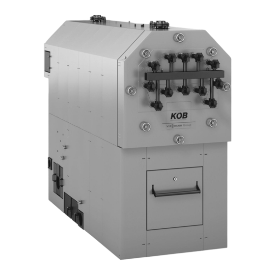
PYROTEC 2.1 Product description A 3-pass boiler (3 bar or 6 bar) B External grate with primary air 2 C Safety heat exchanger D Secondary air E Ignition fan F Supply screw conveyor with separating barrier G Combustion retort with internal grate and primary air 1 H Removal of ash K Combustion chamber door L Moving infeed grate... -
Page 8: Specification
PYROTEC (cont.) 2.2 Specification Specification Trade name PYROTEC grate combustion Rated output 1250 Part no.: 7423 674 7423 675 7423 676 7423 677 7423 678 Output data Rated output 1250 1250 Continuous output Minimum output Q 1210 Output with woodchips W 45 Heating data Content on hot gas side 1540... - Page 9 PYROTEC (cont.) Trade name PYROTEC grate combustion Rated output 1250 Part no.: 7423 674 7423 675 7423 676 7423 677 7423 678 Flue gas Average temperature (gross °C Mean flue gas temperature with Q Mean flue gas temperature with Q °C Mass flow rate ;...
- Page 10 PYROTEC (cont.) KR Boiler return KV Boiler flow Dimensions Rated output 1250 2378 2536 2834 3035 3230 2328 2486 2784 2981 3176 4370 4870 5257 5447 5992 2060 2560 2562 2562 3107 1200 1200 1200 1275 1275 2405 2905 2993 2861 3406 1086...
- Page 11 PYROTEC (cont.) A Boiler drain and fill valve G Primary air fan 1 B Boiler return H Boiler water temperature sensor C Return temperature sensor K Boiler flow D Drive, ash removal L Secondary air fan E High limit safety cut-out M Supply screw conveyor F Safety heat exchanger Dimensions...
- Page 12 PYROTEC (cont.) E Light barrier, incandescence O Limit switch, combustion chamber door F Ignition unit P Primary air fan 2 G Cleaning cover, combustion retort Q Drive, infeed grate H Cleaning cover, external grate R Contact sensor, supply screw conveyor K Light barrier ash removal S Limit switch, maintenance cover L Boiler door...
-
Page 13: Control Unit 3. 1 Specification For Pyrocontrol
Control unit 3.1 Specification for Pyrocontrol Programmable logic control (PLC) for the PYROTEC boiler system The control circuit of combustion optimisation with a Lambda probe incl. the control of equipment for fuel charging according to the articles overlaps the output control circuit. With regard to fire protection and listed separately. -
Page 14: Standard Delivery
Control unit (cont.) Standard delivery: ■ Control panel loose; surface powder-coated. Version as per ÖVE/ ■ Sensors and switches at the combustion block and in the flue outlet VDE directives fully wired to terminal strips, fed 3 x 400 V 50 Hz; (installation on site): control voltage 230 V or 24 V;... -
Page 15: Accessories For Pyrocontrol
Control unit (cont.) 3.2 Accessories for Pyrocontrol External drive control Part no. 7387 802 Note Control of an external conveyor drive or a rotary lock valve without The customer is resopnsible for the delivery and installation of the reversing. The motors are protected against overload and switched off safety switch of the external conveyor drive. -
Page 16: Accessories For Pyrocontrol Output Management
Control unit (cont.) 3.3 Accessories for Pyrocontrol output management Cylinder management 5 sensors (QM) Part no. 7387 809 Standard delivery: Modulating output operation is optimised with the use of a DHW cyl- ■ 5 additional sensors PT-1000 with sensor well 1/2" x 280 mm inder. -
Page 17: Requirement, Additional Heat Source Kp1
Control unit (cont.) Requirement, additional heat source KP1 Part no. 7387 905 Function The additional heat source supplies, individually or jointly with the boiler, heat to the cylinder. This is designed as a low loss header. Taking into consideration the inertia of the boiler, control is carried out so that the additional heat source covers the peak load and the boiler covers the base load. -
Page 18: Accessories For Pyrocontrol Remote Transfer
Control unit (cont.) 3.4 Accessories for Pyrocontrol remote transfer Fault message device, analogue with battery Part no. 7387 840 To be carried out on the customer side: Transmission of fault messages of boiler system either as SMS on a ■ Electrical connection of the phone line to the modem mobile or as a fax. -
Page 19: Mastercontrol For Two-Boiler Systems
Control unit (cont.) 3.5 Mastercontrol for two-boiler systems The Mastercontrol optimises the entire heat generation of two biomass boilers (PYROTEC dual system) incl. control of an oil, gas or electric boiler as a redundancy and/or as a peak load boiler. Trade name Mastercontrol for Boiler combination... - Page 20 Control unit (cont.) Schematic diagram PYRO- PYRO- CONTROL CONTROL MASTER- B28.1 CONTROL PYROTEC 1 PYROTEC 2 B28.2 B28.3 B28.4 B28.5 PYRO- PYRO- CONTROL CONTROL (ECOTRONIC) MASTER- CONTROL A Additional heat source E Charging exclusively boiler 1 in control unit boiler 1 B Flow consumers F Charging exclusively boiler 2 in control unit boiler 2 C Cylinder as low loss header...
-
Page 21: Accessories For Mastercontrol
Control unit (cont.) 3.6 Accessories for Mastercontrol Heat meter signal Part no. 7387 975 Function With this analogue input (0-10 V signal), the external heat meter can be read into the Mastercontrol. The current values can be displayed. The heat meter data is archived in the visualisation. Requirement, additional heat source KP0 Part no. -
Page 22: Fault Message Device, Analogue With Battery
Control unit (cont.) Fault message device, analogue with battery Part no. 7387 840 To be carried out on the customer side: Transmits the boiler system fault messages as a phone message. The ■ Electrical connection of the phone line to the modem fault message must be acknowledged. -
Page 23: Heating Water Buffer Cylinder 4. 1 Specification, Buffer Cylinder
Heating water buffer cylinder 4.1 Specification, buffer cylinder Note Specification and information on request. PYROTEC... -
Page 24: Installation Accessories 5. 1 Boiler Accessories
Installation accessories 5.1 Boiler accessories Flue gas recirculation Standard delivery: ■ Supply line for gas mixture incl. covers for the combustion block ■ Inlet line made from heat-resistant steel, from flue outlet to inlet (internal and external grates) adaptor ■ Software module in the control unit ■... -
Page 25: Boiler Safety Equipment
Installation accessories (cont.) 5.2 Boiler safety equipment Thermally activated safety valve 100 °C Part no. 7387 405 Standard delivery: Standard version for response temperature fixed approx. 100° C, con- ■ Thermally activated safety valve incl. sensor well nection R ¾ Note We recommend the thermally activated safety valve. -
Page 26: Accessories, Heat Distribution
Installation accessories (cont.) 5.3 Accessories, heat distribution Motor three-way valve Designation Part no. Motor three-way valve, VBF 21.80/SQL 33 (ZH-3-80) 7388 260 Motor three-way valve, VBF 21.100/SQL 33 (ZH-3-100) 7388 165 Motor three-way valve, VBF 21.125/SQL 33 (ZH-3-125) 7388 053 Rated output Type DN [mm]... -
Page 27: Accessories, Flue System
Installation accessories (cont.) 5.4 Accessories, flue system Flue gas dust extractor 240/800 The flue gas dust extractor minimises dust emissions and is designed Standard delivery: as a multi-cyclone with axial function. The dust extractor is fully insu- ■ 1 flue gas dust extractor 240 or 800 lated and has three covers for cleaning. - Page 28 Installation accessories (cont.) øa øa < 200 240 l 800 l 1200 1200 Positioning in 4x 90° possible. (Removal, ash container.) A Flue gas fan (with variable rotation) C Dust extractor (axial cyclone) ■ Either top or side D Ash station ■...
-
Page 29: Accessories, Cleaning Pneumatic
Installation accessories (cont.) Dimensions Rated output 1250 Volume Part no. 7423 679 7423 680 7423 681 7423 682 7423 683 Weight with flue gas fan Dimensions 2359 2359 2491 2444 2639 3186 3186 3378 3452 3717 1330 1330 1462 1462 1657 1256 1256... -
Page 30: Price Reduction Net Compressed Air On Site
Installation accessories (cont.) Price reduction net compressed air on site Part no. 7388 288 ■ Compressor (rotation compressor) for utility applications This eliminates the need for the compressor listed in the item "Cleaning – Supply output 160 l/min pneumatic". The compressor provided by the customer must supply at –... -
Page 31: Accessories, Ash Removal
Installation accessories (cont.) 5.5 Accessories, ash removal External container Complete screw conveyor ash removal from the ash chamber into an Standard delivery: external movable zinc-plated ash box. The level in the ash trough is ■ Combustion chamber conveyor made from heat-resistant steel monitored by means of the light barrier. -
Page 32: Extension Of Ascending Screw Conveyor
Installation accessories (cont.) 22,07 mm 1793 8,74 mm 9,13 mm 16,14 mm 1311 Ash removal into an external container with a hopper volume of 240 l Ash container hopper volume Part no. 7387 415 22,07 mm 1793 14,77 mm 1200 16,00 mm 1299 21,03 mm... -
Page 33: Extension Of Combustion Chamber Screw Conveyor
Installation accessories (cont.) Extension of combustion chamber screw conveyor Part no. 7388 037 Note Per metre Design information 6.1 System design Selection of rated output Select the wood boiler according to the required heat load. The Pyrotec Note should be planned as a base load boiler and always operated in con- In places more than 1800 metres above sea level, the project enquiry junction with a buffer cylinder (management). -
Page 34: Installation
Design information (cont.) 45° A Lifting eyes (screw in before lifting) B Lifting eyes (heat exchanger) 6.4 Installation Requirements for boiler room A separate dry boiler room must be provided for the system. No com- ■ Avoid air contamination through halogenated hydrocarbons (e.g. as bustible materials should be stored in the boiler room. -
Page 35: Requirements Of Sample Combustion Order
Design information (cont.) < 400 Hatched surface Floor in heat-resistant version Surface medium grey Boiler supporting surface Foundation properties Trade name PYROTEC grate combustion Rated output 1250 Part no: 7423 674 7423 675 7423 767 7423 677 7423 678 1026 1026 1112 1360... -
Page 36: Minimum Clearances
Design information (cont.) Never close or obstruct combustion air apertures and lines. Use spe- The required cross-section must not be blocked by any closure or cial safety measures to ensure that the combustion equipment can grille. only be operated when the aperture is open. Minimum clearances 10,20 mm >... -
Page 37: Boiler Circuit And Shunt Pumps
Design information (cont.) Connect all heat consumers or heating circuits to the boiler flow and Easy installation return connectors. Never make any connections to the safety flow or For safety temperatures up to 110 ºC, the boiler requires no inter- to other connections. - Page 38 Design information (cont.) Sizing recommendation for systems with sealed expansion, cylinder circuit if required --B28.1-- --B28.2-- --B28.3-- Example Additional heat source Distributor, heat consumer 1 cylinder as low loss header (5 sensors) PYROTEC...
-
Page 39: Electrical Installation
Design information (cont.) Buffer cylinder Additional heat source controlled with a directional control valve More than 1 buffer cylinder as low loss header (5 sensors) - Oil/gas boiler Buffer cylinder 2 - Electric heater Buffer cylinder 1 With additional heat source, dual mode - Oil, gas, electric Low loss header M20 Boiler pump... -
Page 40: Extinguishing Water Container
Design information (cont.) Extinguishing water container Part no. 7387 785 C Material supply D Combustion Note Part of the boiler. Note ■ Adjustment, valve, Danfos AVTA 15 50–90 °C 3 corresponds to 80 C°. ■ Lines should be secured in metal pipes (½“). ■... -
Page 41: Prevention Of Combustion Chamber Overfilling
Design information (cont.) Prevention of combustion chamber overfilling In accordance with TRVB 118, a fill level monitor should be installed As a result, any prescribed protection device does not come into effect to prevent overfilling of the combustion chamber. The boiler has two and normal operation is maintained with regard to the greatest possible light barriers for incandescence monitoring. -
Page 42: Minimum Pressure Limiter
Design information (cont.) Minimum pressure limiter Recommended for flow temperatures in excess of 100 ºC. One required per multi boiler system. Safety valve Equip the boilers to EN 12828 with a type-tested safety valve. For all The pipework between the boiler and the safety valve must not be able other operating conditions, this must be identified in accordance with to be shut off. -
Page 43: Fuel
Design information (cont.) 6.10 Fuel The PYROTEC grate combustion has been specially developed for the automatic combustion of dry and moist wood fuels (waste wood, wood pellets or woodchips from forest thinnings up to max. W50). It com- bines the benefits of underfeed combustion with the advantages of grate combustion to optimum effect. -
Page 44: Drive, Discharge Conveyor, Pellets
Design information (cont.) 5,92 mm 77,60 mm 24,36 mm <200 7,53 mm 5,15 mm 180x180 102,15 mm 14,79 mm 14,03 mm 4,96 mm ~ 500 166 1,48 mm C - C 9,79 mm 6,21 mm 10,20 mm 24,31 mm 40,28 mm A Possible outlet into a bunker C Intermediate floor B Optional drive left or right... -
Page 45: Fuel Discharge By Means Of Agitators
Design information (cont.) ■ Control of spur geared motor 3 x 400 V according to boiler control unit ■ Inspection cover with safety limit switch and sealed outlet 6.12 Fuel discharge by means of agitators Spring core discharge AF Part no. 7387 964 for spring core discharge 3.5 m Part no. - Page 46 Design information (cont.) Sizing ø a 4,14 mm 52,24 mm ø 150 72,64 mm 11,89 mm < 6000 24,75 mm 8,80 mm 13,20 mm 22,00 mm A Second leaf spring D Shavings B Installation opening E Remainder (seal with fire-retardant panel) F Pellets C Rotational direction G Base (height adjustable)
-
Page 47: Discharge Screw Af To Spring Core Discharge
Design information (cont.) Note 1. Installation position, horizontal: preferably in concrete with recess for screw conveyor and central gear 2. Installation position, angled: exclusively with intermediate floor, preferably made from wood 3. Suitable for woodchips up to G30/50; not suitable for wood bri- quettes and shredded matter from used or waste wood 4. - Page 48 Design information (cont.) 42,99 mm 4,33 mm 18,03 mm ø 1490 34,54 mm37,56 mm 14,59 mm < 200 7,29 mm > 10000 A Axis, agitator C Rotational direction B Screw axis D Centre, agitator Sizing the horizontal discharge AH with agitator and discharge screw Min.
- Page 49 Design information (cont.) 76,25 mm > 10000 3,65 mm < 200 < 170 < 600 1,52 mm 33,67 mm L1 + 200 1260 PYROTEC...
-
Page 50: Discharge Screw Ah For Horizontal Discharge
Design information (cont.) Installation position, horizontal (version 1) D Axis, screw conveyor Installation position, sloping (version 2) E Axis, agitator Finished floor, concrete-lined (concrete block out for recessed F Sub-structure installation) G Building floor A Finished floor H Centre, agitator B Seal installation opening with fire-retardant panel K Concrete block out (for recessed installation) C Height adjustable base... -
Page 51: Fuel Discharge By Means Of Funnel Discharge
Design information (cont.) 6.13 Fuel discharge by means of funnel discharge Funnel discharge Material discharge for round silos is carried out with an agitator inte- Standard delivery: grated in the discharge casing. In its centre, the discharge screw is ■ Funnel discharge as per order data with drive unit 3 x 400 V driven via a solid universal joint. -
Page 52: Additional Outlet Flange
Design information (cont.) Version and drives Funnel discharge AP-11 AP-12 AP-Z02 Part no. 7387 899 7387 929 7388 042 2205 3005 3005 1030 1030 Additional outlet flange Part no. 7388 520 Additional connection option for supply equipment to discharge casing for twin-boiler system. -
Page 53: Specification For The Pushrod Drives
Design information (cont.) Max. permissible dumping height and length of the pushrods in S650 Trade name Pushrod Type AS-2.50 AS-2.25 AS-2.0 AS-1.75 AS-1.5 Part no.: 7387 992 7387 995 7387 836 7387 956 7387 989 Dumping height with length: Specification for the pushrod drives Trade name Pushrod drive Type... -
Page 54: Slot Discharge, For Pulling
Design information (cont.) FZD Maximum pressure force on the weld base for the pushrod drive FZZ Maximum tensile force on the weld base for the pushrod drive Number of pushrods 1x FS1 1x FS1 2x FS1 1x FR1 1x FR1 Standard version 160 kN 130 kN... -
Page 55: Centre Discharge
Design information (cont.) 10,29 mm 6,02 mm 0,89 mm 19,48 mm 9,50 mm 1230 27,72 mm > 1750 95,02 mm (4000 - 12000) 0,48 mm 50 - 150 A - A Required order data for the above example: Position Part no. Quantity Unit Designation... - Page 56 Design information (cont.) Specification Centre discharge Screw Screw D = 190 mm D = 250 mm For max. dumping height, see page 52 For max. dumping height, see page 52 In the middle third of the silo length In the middle third of the silo length >...
-
Page 57: Slot Discharge With Fill Function
Design information (cont.) Required order data for the above example: Position Quantity Unit Designation Pushrod drive AS individual with hydraulic cylinder type K Weld base, bunker Cover, centre discharge Push floor screw conveyor Pushrod (incl. stop wedges) Version and drive, AQ standard Hydraulic compartment Hydraulic drive, ASH individual Weld base, AS individual... - Page 58 Design information (cont.) 9,71 mm 5,86 mm 3,57 mm 16,78 mm 9,32 mm 1080 > 3000 46,60 mm 15,53 mm 0,50 mm A - A 50 - 150 46,60 mm 46,60 mm < 8000 < 12000 93,20 mm (< 20000) 3,03 mm 0,54 mm 50 - 150...
-
Page 59: Fuel Discharge By Means Of Push Floor (Accessory)
Design information (cont.) Required order data for the above example: Position Quantity Unit Designation Pushrod drive AS twin with hydraulic cylinder type K Cover for push floor screw conveyor (optional) Weld base, bunker Pushrod (incl. stop wedges) Push floor screw conveyor Version and drive, AQ standard Hydraulic drive, ASH twin Weld base, AS twin... -
Page 60: Pushrod
Design information (cont.) To be carried out on the customer side: Note ■ Manufacturing the concrete floor Article price per m ■ Installation of the profiles level with the concrete floor (max. deviation Total price is calculated as follows: of 5 mm to 10 m) For pushrod drive, individual: (pushrod drives in pce x length of bunker in m) + (1 x width of bunker in m) x article price For pushrod drive, twin: (pushrod drives in pce x length of bunker in... -
Page 61: Hydraulic Drive, As Twin
Design information (cont.) Hydraulic drive, AS twin Hydraulic drive to activate twin pushrod drives with discharge and fill ■ Control of discharge function: function. When the required fill level of the push floor screw conveyor according to the boiler control unit, fuse protected with temperature is reached, the discharge function is switched off. -
Page 62: Drive, Push Floor Screw Conveyor, Standard
Design information (cont.) Drive, push floor screw conveyor, standard Part no. 7387 925 Standard delivery: Standard version for push floor screw conveyor with pulling drive and ■ Drive unit with spur geared motor 400 V and chain drive discharge into a drop section. The system is driven via a spur geared ■... -
Page 63: Drive, Trough Screw Conveyor, Standard
Design information (cont.) A - A 7,54 mm 1,11 mm 6,40 mm > 30 5,51 mm 5,80 mm 6,38 mm 13,77 mm 4,82 mm 14,51 mm ~ 500 A Drive (optionally on the l.h. or r.h. side) B Inspection clearance Trade name Trough screw conveyor Type... - Page 64 Design information (cont.) The pipe screw conveyor is ideal for conveying pourable wood fuels Note and/or in the case of steep ascending inclines. Article price per m Total price: Length L in m x article price Standard delivery: ■ Pipe screw conveyor according to the project drawing Trade name Pipe screw conveyor Part no:...
-
Page 65: Drive, Pipe Screw Conveyor, Pellets
Design information (cont.) 13,90 mm 3,36 mm 10,55 mm 5,99 mm 2,56 mm 5,25 mm 4,60 mm A Drive (optionally on the l.h. or r.h. side) D Pipe screw conveyor, vertical, pushing B Distributing container E Pipe screw conveyor, horizontal, pushing C Distributing screw conveyor Drive, pipe screw conveyor, pellets Part no. -
Page 66: Drive, Pipe Screw Conveyor, Standard
Design information (cont.) Drive, pipe screw conveyor, standard Part no. 7387 843 Standard delivery: Standard version for pipe screw conveyor with pulling drive and dis- ■ Drive unit with spur geared motor 3 x 400 V and chain drive charge into a drop section. The system is driven via a spur geared ■... -
Page 67: Pellet Storage Room Design And Required System Components
Design information (cont.) ≥ 500 mm 40° A Fill connector E Empty space B Return air connector F Discharge system G Available volume = ⅔ of the room C Air space D Slanted floor Pellet storage room design and required system components ≥... -
Page 68: Additional Safety Instructions For Pellet Stores
Design information (cont.) ■ The pellet storage room must be dry, as pellets will swell up markedly ■ Avoid the installation of water pipes inside the storage room because if exposed to moisture. This leads to substantial difficulties in deliv- of condensation and the risk of burst pipes. - Page 69 Design information (cont.) Connector length and location If connectors must be located on the long side of the storage room, we The length of the fill connector is subject to the distance from the return recommend alternating the filling between the connectors. This air connector.
- Page 70 Design information (cont.) Connector installation options Setting into brickwork The connector is bricked into the opening without thermal insula- tion. A Fill connector B Wall outlet Ø 150 mm Wall installation with screws C Pipe clip for earthing The connector is secured to the outside wall with screws and is earthed D Wall outlet Ø...
-
Page 71: Fuel Storage In On-Site Pellet Store (Accessories)
Design information (cont.) Installation into a lighting duct C Extension pipe Connectors may be installed through a wall or through a window open- D Wall outlet Ø 110 mm ing. The shortened fill and return connectors are inserted in a 45 º bend. -
Page 72: Extension, Blast Pipe, Straight
Design information (cont.) Extension, blast pipe, straight Part no. 7388 056 Standard delivery: ■ Extension DN 100, length 700 mm, zinc-plated ■ Union nut for fitting ■ Clip for fastening 45° bend for blow line Part no. 7388 052 Standard delivery: ■... -
Page 73: Bunker Cover Hydraulic Fdh
Design information (cont.) A All-round seal (not included in standard delivery) B Rod clearance, fall protection grille C Secured with 10 x screws Bunker cover hydraulic FDH Cover for secure sealing of openings for wood fuel delivery. The cover ■ Hydraulic cylinder with hinge lug connection, pipe break protection, is controlled manually using a hydraulic cylinder. - Page 74 Design information (cont.) 62,77 mm A Fall protection grille (optional) B Rubber apron C All-round seal, required, not included in standard delivery Recommendation: Kemperol combi roof seals Specification FDH 4.0/2.4 FDH 5.5/2.4 FDH 7.0/2.4 FDH 8.5/2.4 Type 7388 011 7387 903 7387 834 7387 884 Part no.
-
Page 75: Fall Protection Grille 120 For Fdh
Design information (cont.) Fall protection grille 120 for FDH Fall protection grille for corresponding bunker cover in several ele- Standard delivery: ments to prevent anyone falling in when the cover is open. Each ele- ■ Support profile for installation in ceiling recess ment is prepared for installation of a shaker motor (shaker motor at an ■... - Page 76 Design information (cont.) 1,90 mm ø102 37,68 mm 56,10 mm 1,87 mm 58,53 mm 1,87 mm ±0,0 A Filling on customer side (concrete or asphalt) E Filling level B Channel for rainwater F Fall protection grille (optional) C Rainwater drain (on site) G All-round seal (required) (on site) D Threaded fitting H Drain channel, running water (on site)
-
Page 77: Fall Protection Grille, 120 For Fdb
Design information (cont.) Specification Bunker cover, movable FDB FDB 3.0/2.0 m FDH 3.8/2.4 m FDH 3.2/3.2 m Part no. 7387 850 7387 793 7387 974 3000 3800 3200 2110 2510 3310 2000 2400 3200 3150 3950 3350 2530 2930 3730 2150 2550 3310... -
Page 78: Cover Drives For Hydraulic Drive, Ash
Design information (cont.) – Hydraulic hoses Note – Wall mounting brackets Application in the case of silo discharge systems without hydraulic ■ Control: activation (AF, AG, AP, external discharge) – According to the boiler control unit, fuse protected with tempera- ture and level switch in the oil container ■... -
Page 79: Back Burning Protection
Design information (cont.) 10,19 mm 1,54 mm 1300 13,51 mm < 1500 6.20 Back burning protection Rotary lock valve Rotary lock valve for fire protected separation of combustion system Note and fuel store with overpressure or underpressure, and with simulta- Rotary lock valve 190 for supply system D 120 mm neous material transportation for installation in a drop section. -
Page 80: Shut-Off Gate Valve Ma 220
Design information (cont.) Trade name Rotary lock valve Type MZ 190 MZ 260 Part no: 7387 967 7387 422 7193 7264 d (Di) e (Da) e (Di) e (Da) Output, drive 0.75 0.75 Drive speed Shut-off gate valve MA 220 Part no. -
Page 81: Connection On The Flue Gas Side
Design information (cont.) 6.21 Connection on the flue gas side Chimney The system is equipped with a flue gas fan and therefore combustion A chimney compliant with regulations relevant to the rated boiler output equipment without draught requirement. The chimney sizing should be is required for efficient boiler operation. -
Page 82: Sound Insulation
Design information (cont.) 6.22 Sound insulation Braces To avoid the transmission of structure-borne noise during the opera- Standard delivery: tion of the fuel transportation equipment, the braces and the anchors ■ Sylomer washer of the relevant conveyor device are placed on high quality Sylomer ■... -
Page 83: General Information Regarding Low Pressure Hot Water Boilers With Safety Temperatures Of Up To 110 ºc
Appendix (cont.) Selected: Recommendations: 1 x diaphragm expansion vessel N 250 (from Vitoset pricelist) ■ Select a sufficiently high safety valve response pressure: ≥ p + 1.5 bar ■ All details relate to a flow temperature of 90 °C. ■ For circulation pumps, due to the inlet pressure required, select at ■... -
Page 84: Flue System
Appendix (cont.) 7.6 Flue system Only flue pipes that meet Building Regulations may be used with con- densing systems. 7.7 Checks as part of the Building Regulations approval process As part of the Building Regulations approval process, condensing The State Building Regulations, their implementation orders and the combustion equipment is tested by the flue gas inspector (where appli- combustion equipment orders, as well as the general building appro- cable) for adherence to Building Regulations and any generally rec-... -
Page 85: Keyword Index
Keyword index Accessories Low water indicator................41 ■ For control unit............15, 16, 18, 19, 21 ■ For the boiler.................25 Agitators Mastercontrol................19, 21 ■ Discharge system.................45 Maximum pressure limiter..............41 Minimum pressure limiter..............42 Minimum wood fuel requirements............6 Boiler circuit pump................37 Boiler room..................34 Building Regulation approval process..........84 Output management................16 Bunker cover ■... - Page 86 PYROTEC...
- Page 87 PYROTEC...
- Page 88 Subject to technical modifications. Viessmann Werke GmbH&Co KG Köb Holzheizsysteme GmbH D-35107 Allendorf Flotzbachstrasse 33 Telephone: +49 6452 70-0 A-6922 Wolfurt Fax: +49 6452 70-2780 Telefon: +43 (0)5574 6770-0 www.viessmann.com Telefax: +43 (0)5574 65707 www.koeb-holzfeuerungen.com PYROTEC...
Need help?
Do you have a question about the KOB PYROTEC and is the answer not in the manual?
Questions and answers