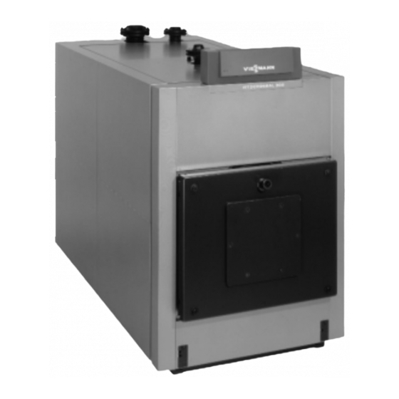
Floor mounted, gas-fired condensing boiler with matrix gas burner and lambda pro control, for operation with natural gas and liquid propane gas, heating input 19 to 199 mbh, 5.6 to 58 kw, with vitotronic 200 kw6b controls (44 pages)
(on site) 5. Modulating burner operation None burner adjustment (on site) 6. Reduced operation None total reduction possible the Viessmann control unit sup plied with the system 7. Weekend reduction None total reduction possible same as reduced operation " Please note:...
1.3 Boiler control units 1.3 Boiler control units (See technical data sheets of the boiler control units for detailed description) The standard specification of all Viess The temperature sensors are closely Vitotronic 333 (Type MW1S) for 1 to 4 mann boilers includes a boiler control matched to the characteristics of the boilers and 2 heating circuits each with unit which is specially matched to the...
1.3 Boiler control units 1.4 Switching points and temperature limits Control equipment for multi-boiler system Vitocontrol control cabinet Vitotronic 333 (Type MW1) with Vitotronic 333 (Type MW1S) = ATS up to 4 boilers with Vitotronic 100 (Type GC1) 1.4 Switching points and temperature limits Outdoor temperature in ºC 1 Adjustment facilities of the high limit 2 Adjustment facilities of the tempera...
2.1 General notes on planning 2.1 General notes on planning Delivery, transport to and installation in the boiler room Delivery On the Vitocrossal 300 (Type CT3) with The boilers can stand on a level concrete We use crane trucks for delivery to and rated outputs of 170 to 595 kW, the front floor without any special foundation.
Flow temperatures Safety temperatures Choosing the rated output In order to minimize distribution losses, The Viessmann boilers conform to EN 303 The boiler should be selected on the we recommend that the and DIN 4702 and are type-tested. They basis of the required heat demand.
Page 8
2.2 Hydraulic connections Hydraulic connections for condensing technology H Due to the low return temperatures re The high efficiencies of Vitocrossal 300 H The water flows in the heating circuits quired for flue gas condensing, only condensing boilers can be increased even should be reduced by variable speed 3-port mixing valves may be installed in further by means of the following...
Other abbreviations used Heating circuit Heating circuit pump Heating water return Heating water flow SDB2 1 Equipment comprising Viessmann max. pressure limiting assembly 2 Equipment comprising Viessmann min. pressure limiting assembly General notes Low water indicator Safety valve Flash trap...
Page 10
2.3 Safety equipment Selection table for safety equipment The table shows which safety equipment is required for the system version concerned according to DIN 4751-2. (× = Required, = Not required) Rated output of boiler x 350 kW > 350 kW Safety temperature 100 ºC 110 ºC...
Unit burners (see technical data sheet for the boiler Viessmann gas pressure jet burners are concerned). available for Vitocrossal 300 boilers with outputs of 80 and 105 kW.
2.6 Flue systems 2.6 Flue systems Flue systems Current regulations on flue systems state H The outlet points of chimney stacks and the following requirements: flue ducting must H Flue systems must be suitably sized in project at least 40 cm above the roof terms of their cross-section and height ridge or be at least 1 metre from the and, where necessary, also in terms of...
2.7 Flue system 2.7 Flue system for Vitocrossal 300, 80 to 460 kW Due to the low flue gas temperature, the Inside buildings, flue systems should only Please note: resulting lower up-draught and the con be run within their own, vertically venti Flue gas temperature protection is not tinued condensing of the flue gases in the lated stacks or ducting which conform to...
Page 14
2.7 Flue system Notice of approval of the polypropylene flue systems for Vitocrossal 300 Extension of approval applied for.
Page 15
2.7 Flue system A flue pipe is required between the gas- System size: Flue pipe dia. 125, 150 and For installation in vertically ventilated fired condensing boiler and the stack and 200 mm. stacks or ducts which conform to the re for installation in the stack for operation A boiler connection adaptor must be or quirements for domestic chimney stacks...
Page 16
2.7 Flue system For running vertically through the roof The maximum vertical pipe length is Vertical flat roof outlet (short-stemmed chimney) where the 6 metres with the following maximum A flat roof collar should be integrated in Vitocrossal 300 up to 130 kW is installed number of bends the roof covering in accordance with the in the roof space...
Page 17
2.7 Flue system Calculating the maximum pipe lengths With the aid of the diagrams on the left it is possible to make an approximate cal culation of the total length (in metres) of the flue pipe up to the boiler connection adaptor.
Page 18
2.7 Flue system Parts for the plastic flue system Basic stack unit comprising: Support bend Support rail System size ∅ mm ∅ mm A System size 125, 150 or 200 Stack cover (fastening materials for securing the stack cover to the coping stone included in the standard delivery) System size ∅...
Page 19
2.7 Flue system Pipe, 2 m long (2 units) Pipe, 2 m long (1 unit) Pipe, 1 m long (1 unit) Pipe, 0.5 m long (1 unit) (the pipes can be shortened if required) System size ∅ mm ∅ mm A System size 125, 150 or 200 Plain inspection pipe section (straight) System size...
Page 20
2.7 Flue system Plain bend (45º) System size ∅ mm ∅ mm A System size 125, 150 or 200 Plain bend (30º) Plain bend (15º) Ventilation flashing System size ∅ mm A Spacer Inspection bend (87º) System size ∅ mm ∅...
Page 21
2.7 Flue system Boiler connection adaptor (separate order required) Boiler 150/ 180/ 200/ 180/ 200/ 250/ connection 150/ 150/ 150/ 200/ 200/ 200/ adaptor ∅ mm ∅ mm A Measuring port B Connection facility for flue gas high limit safety cut-out Reducer (from system size 150 to system size 125/100) System size A System size 100 and 125...
Page 22
2.7 Flue system Vertical concentric roof outlet Universal Roman tile (suitable for roof pitch from 25 to 45º) A Universal Roman tile Flat roof collar Roof construction to guidelines for flat roofs A Gravel layer B Roof insulation C Aeration layer D Thermal insulation E Insulation F Ceiling...
Page 23
2.7 Flue system Connection to moisture-resistant chimney (negative pressure) with flue pipe constructed from plastic (polypropylene) Vitocrossal 300 condensing boilers may be connected to moisture-resistant chimneys provided the chimney manu facturer certifies the suitability of the stack in accordance with DIN 4705. An approved, pressure-tight and mois ture-resistant flue pipe must be used as the connecting pipe.
2.8 Sound insulation 2.8 Sound insulation The burner/boiler systems, circulation On large systems it may be necessary to Structure-borne sound insulation pumps as well as other equipment in feed the intake air in vibration-damped Cushioned supports on the boiler are an stalled in heating systems are a source of ducting to avoid noise outside the build inexpensive and effective means of re...
2.9 Guide values for water condition 2.9 Guide values for water condition The life of any heat generator as well as It is a condition of our warranty that the The principal requirements regarding the that of the complete heating system is requirements described below are com water condition are summarized below.
2.10 Condensate drainage and neutralizing 2.10 Condensate drainage and neutralizing The acid condensate formed both in the Gas-fired systems over 200 kW As the rate of consumption depends on condensing boiler and in the flue pipe Neutralization of the condensate from the pattern of operation of the system, must be discharged into the public drain these systems is generally required.
2.11 Safety rules and regulations 2.11 Important safety rules and regulations General information Gas installation Water used for filling and replenishing The boiler is constructed in accordance The installer is required to carry out gas with TRD 702 and is used in heating sys installation work in accordance with the H VDI 2035: Prevention of damage due to tems conforming to DIN 4751-1/2.
3.1 Circuit diagram 1 Circuit diagram 1 Single-boiler system with Vitocrossal 300 boiler System Functional description Advantages Single-boiler system with: The Vitocrossal 300 is operated with The two heating circuits connected to the H Vitocrossal 300 (80 to 895 kW) modulating boiler water temperature by Vitotronic 300 (Type GW2) are controlled H Vitotronic 300 (Type GW2)
Page 29
3.1 Circuit diagram 1 Installation diagram 2 20 20 52 Connectors sÖ A 1 Heating circuit without mixing gS M 2 Mixing valve motor Outdoor temperature sensor valve (if installed) gS M 3 Mixing valve motor ? M 2 Flow temperature sensor, mixing Circulation pump for heating the lÖ...
3.1 Circuit diagram 2 Circuit diagram 2 Single-boiler system with Vitocrossal 300 boiler with several heating circuits and one modulating flow temperature heating circuit System Functional description Advantages Single-boiler system with: The Vitocrossal 300 is operated with Thanks to the separate return connec H Vitocrossal 300 (80 to 895 kW) modulating boiler water temperature by tions for heating circuits with high and...
Page 31
3.1 Circuit diagram 2 Installation diagram 2 20 20 52 Connectors sÖ A 1 Heating circuit pump for a heat gS M 2 Mixing valve motor Outdoor temperature sensor ing circuit without mixing valve gS M 3 Mixing valve motor ? M 2 Flow temperature sensor, mixing Circulation pump for heating the lÖ...
3.1 Circuit diagram 3 Circuit diagram 3 Multi-boiler system with Vitocrossal 300 boilers with several heating circuits and one modulating flow temperature heating circuit System Functional description Advantages Multi-boiler system with: The Vitocrossal 300 boilers are operated Thanks to the separate return connec H Vitocrossal 300 (80 to 895 kW) with modulating boiler water temperature tions for heating circuits with high and...
Page 33
3.1 Circuit diagram 3 Installation diagram 2 20 52 2 20 52 Connectors sÖ M 2 Heating circuit pump, mixing gS A 1 Motorised butterfly valve Outdoor temperature sensor valve gS M 2 Mixing valve motor ? Fl. Flow temperature sensor, sÖ...
3.1 Circuit diagram 4 Circuit diagram 4 Multi-boiler system with Vitocrossal 300 and Vitoplex boilers with several heating circuits and one modulating flow temperature heating circuit System Functional description Advantages Multi-boiler system with: The Vitocrossal 300 (lead boiler) and the Thanks to the separate return connec H Vitocrossal 300 (80 to 895 kW) Vitoplex follow-up boilers are operated...
3.1 Circuit diagram 4 Installation diagram 2 20 52 2 20 52 Connectors aJ A Therm-Control temperature sensor Burner (1st stage) Outdoor temperature sensor sÖ M 2 Heating circuit pump, mixing gS A 1 Motorised butterfly valve ? Fl. Flow temperature sensor, valve gS M 2 Mixing valve motor common heating flow pipe...
Page 36
3.1 Circuit diagram 5 Circuit diagram 5 Multi-boiler system with Vitocrossal 300 and Vitoplex boilers with several heating cir cuits and one modulating flow temperature heating circuit Vitoplex with shunt pump System Functional description Advantages Multi-boiler system with: The Vitocrossal 300 (lead boiler) and the Thanks to the separate return connec H Vitocrossal 300 (80 to 895 kW) Vitoplex follow-up boilers are operated...
Page 37
3.1 Circuit diagram 5 Installation diagram 2 20 52 2 20 52 Connectors aJ A T 1 temperature sensor Burner (1st stage) Outdoor temperature sensor aJ B T 2 temperature sensor gS A 1 Motorised butterfly valve ? Fl. Flow temperature sensor, sÖ...
Page 38
3.1 Circuit diagram 6 Circuit diagram 6 Multi-boiler system with Vitocrossal 300 and Vitoplex 300 boilers with several heating circuits and one modulating flow temperature heating circuit Vitoplex 300 with Therm-Control and boiler circuit pump System Functional description Advantages Multi-boiler system with: The Vitocrossal 300 (lead boiler) and the Thanks to the separate return connec H Vitocrossal 300 (80 to 895 kW)
Page 39
3.1 Circuit diagram 6 Installation diagram 2 20 52 2 20 52 Connectors aJ A Therm-Control temperature sensor Burner (1st stage) Outdoor temperature sensor sÖ M 2 Heating circuit pump, mixing gS M 2 Mixing valve motor ? Fl. Flow temperature sensor, valve gS M 3 Mixing valve motor common heating flow pipe...
Page 40
3.1 Circuit diagram 7 Circuit diagram 7 Multi-boiler system with Vitocrossal 300 and Vitoplex 300 boilers with 3-port mixing valve and several heating circuits plus one modulating flow temperature heating circuit System System-specific coding Please note: At least 15 % of the take-off On the Vitotronic 333 from the rated output must be connected Change "3B"...
Page 41
3.1 Circuit diagram 7 Installation diagram 2 20 52 2 20 52 Connectors aJ A T 1 temperature sensor Burner (1st stage) Outdoor temperature sensor sÖ M 2 Heating circuit pump, mixing gS A 1 3-port mixing valve ? Fl. Flow temperature sensor, valve gS M 2 Mixing valve motor...
3.2 Domestic hot water heating with cylinder loading system 3.2 Domestic hot water heating with cylinder loading system The Viessmann cylinder loading system is H heating systems for which low return H short periods of peak output, i.e. high a combination comprising a Vitocell-L...
3.3 Notes on installation 3.3 Notes in installation Connection of a control unit provided on site to the Vitotronic 100 (Type GC1) Operation with two-stage burner Floating contacts of the master control Coding changes required in the Vito unit: tronic 100 (see service instructions): Single-boiler systems: Change coding "01"...
Page 44
3.3 Notes on installation Operation with modulating burner on the Vitocrossal 300 (modulation controller provided on site) Connection of modulating burners: H 1st stage burner fA from Vitotronic 100 H Connector lÖ from Vitotronic 100 re mains free H 2nd stage burner lÖ modulating from modulation controller installed on site Contacts of the master control unit with H 1st stage burner released by the mo...
Page 45
3.3 Notes on installation Operation with modulating burner on the modulating boiler (modulation controller provided on site) Connection of modulating burners: H 1st stage burner fA from Vitotronic 100 H connector lÖ from Vitotronic 100 via modulation controller (installed on site) to connector lÖ...
Page 46
3.3 Notes on installation Additional connection facilities on Vitotronic 200, 300 and 333 External load-dependent switch-on When the floating contact between ter The boiler water temperature is limited by minal "2" and "3" on the plug-in connec the preset max. boiler water temperature tion aVH closes, the burner of the boiler or by the value set on the mechanical and, where applicable in the case of the...
Page 47
3.3 Notes on installation External changeover of heating program/Open mixing valves Also applicable to Vitotronic 050 The manually preselected heating pro switch contact at connector aVD, terminal gram can be changed or the connected "1" and "2". mixing valves opened via the floating ´...
Page 48
Subject to technical modifications. tems and equipment regardless of manu facturer. Viessmann Werke GmbH & Co For example, individual room controls or D-35107 Allendorf building management systems can be Tel: (06452) 70-0...
Need help?
Do you have a question about the Vitocrossal 300 CT3 and is the answer not in the manual?
Questions and answers