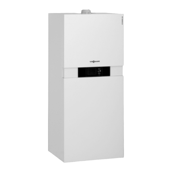
Viessmann Vitodens 222-F Installation And Service Instructions Manual
Type b2tb, 1.8 to 35.0 kw, gas condensing storage combi boiler, natural gas and lpg version
Hide thumbs
Also See for Vitodens 222-F:
- Installation and service instructions manual (172 pages) ,
- Installation and service instructions for contractors (156 pages) ,
- Technical manual (156 pages)
Table of Contents
Advertisement
Quick Links
Advertisement
Chapters
Table of Contents

Related Manuals for Viessmann Vitodens 222-F


Summary of Contents for Viessmann Vitodens 222-F
- Page 1 VIESMANN Installation and service instructions for contractors Vitodens 222-F Type B2TB, 1.8 to 35.0 kW Gas condensing storage combi boiler Natural gas and LPG version For applicability, see the last page VITODENS 222-F Please keep safe. 5789330 GB/en 11/2017...
- Page 2 Hot surfaces can cause burns. Replace faulty components only with genuine ■ Before maintenance and service work, switch Viessmann spare parts. OFF the appliance and let it cool down. Never touch hot surfaces on the boiler, burner, ■ flue system or pipework.
- Page 3 For replacements, use only original spare parts supplied or approved by Viessmann. Safety instructions for operating the system If you smell gas Condensate Danger...
-
Page 4: Table Of Contents
Disposal of packaging ................Symbols ....................Intended use ..................Product information ................Vitodens 222-F, type B2TB ..............■ 2. Preparing for installation Preparing for boiler installation .............. Safety assembly to DIN 1988 and EN 806 on the cold water connec- tion ...................... - Page 5 Index Index (cont.) 8. Troubleshooting Fault display ................... 64 Fault codes .................... 64 Maintenance ..................74 Putting the control unit into the service position ......... 74 ■ Draining the boiler on the heating water side ........75 ■ Checking the boiler water temperature sensor, cylinder temperature ■...
-
Page 6: Disposal Of Packaging
Please dispose of packaging waste in line with statu- DE: Use the disposal system organised by tory regulations. Viessmann. AT: Use the ARA statutory disposal system (Altstoff Recycling Austria AG, licence number 5766). CH: Packaging waste is disposed of by the HVAC contractor. -
Page 7: Intended Use
■ Hydraulics with 3-way diverter valve and variable The Vitodens 222-F may only be delivered to countries speed high efficiency circulation pump listed on the type plate. For deliveries to other coun- Vitotronic 100 for constant temperature operation tries, approved contractors must arrange individual ■... -
Page 8: Preparing For Boiler Installation
Preparing for installation Preparing for boiler installation Use a connection set or connection kit, available as an Note accessory, to make the connection on the gas and Fit safety equipment in accordance with the national water sides. regulations. Fitting accessories Please note Fit all accessories that are installed at the back of the Avoid damaging the appliance. - Page 9 Preparing for installation Preparing for boiler installation (cont.) 1. Prepare the connections on the heating water side. Thoroughly flush the heating system. Note If an on-site expansion vessel also has to be instal- led: Install this expansion vessel in the heating return, as the 3-way diverter valve is located in the heating flow.
-
Page 10: Safety Assembly To Din 1988 And En 806 On The Cold Water Connection
Preparing for installation Safety assembly to DIN 1988 and EN 806 on the cold water connection Fig. 4 Safety assembly (accessories for connection sets Drain outlet for unfinished walls) Cold water Safety valve Drinking water filter Visible discharge pipe outlet point Pressure reducer to DIN 1988-2, Dec. -
Page 11: Removing The Front Panels
Installing the boiler Removing the front panels Fig. 5... -
Page 12: Siting And Levelling The Boiler
Installing the boiler Siting and levelling the boiler Note Position the appliance and accessories so that they are flush with the wall. SW17 Fig. 6 Fitting the additional type plate 1. Take the additional type plate from the documenta- 2. In consultation with the system user, attach the tion supplied with the boiler. -
Page 13: Connections On The Heating Water And Dhw Side
Installing the boiler Connections on the heating water and DHW side Fig. 7 Shown with connection sets for finished walls (accessories) Heating flow R Cold water R ¾ ½ DHW R Heating return R ½ ¾ DHW circulation R (separate accessories) ½... -
Page 14: Flue Gas Connection
Flue system installation instructions. flue system" enclosed with the technical documenta- tion may only be used in conjunction with the Viessmann flue system made by Skoberne. ■ During installation and positioning of the flue system, observe Building Regulations Part L and BS 5440 [GB only]. -
Page 15: Gas Connection
Installing the boiler Gas connection Fig. 9 1. If the gas connection has not been fitted previ- 3. Purge the gas line. ously, seal gas shut-off valve to the gas con- nection. Conversion to alternative gas types: See "Commissioning, inspection and mainte- Information on operation with LPG nance". -
Page 16: Opening The Control Unit Enclosure
Installing the boiler Opening the control unit enclosure Fig. 10 Electrical connections Please note Electronic assemblies can be damaged by elec- trostatic discharge. Prior to commencing any work, touch earthed objects such as heating or water pipes to dis- charge static loads. - Page 17 Installing the boiler Electrical connections (cont.) 230V~ 230V~ 3 2 1 Fig. 11 Connections to 230 V~ plugs Routing the power cable Power supply fÖ The power cable is connected in the delivered con- dition. ■ Power supply for accessories ■...
-
Page 18: External Demand Via Switching Contact
Installing the boiler Electrical connections (cont.) External demand via switching contact Connection options: Please note EA1 extension (accessory, see separate installation Live contacts lead to short circuits or phase fail- ■ instructions) ure. ■ Plug The external connection must be floating and meet the requirements of protection class II. -
Page 19: External Blocking Via Switching Contact
Installing the boiler Electrical connections (cont.) [{{] 0-10V fÖ Ö Fig. 13 0 to 1 V No specification for set boiler water temperature Set value 10 °C 10 V Set value 100 °C External blocking via switching contact Connection options: Please note Plug Live contacts lead to short circuits or phase fail-... -
Page 20: Power Supply For Accessories At Plug Lh (230 V ~)
Installing the boiler Electrical connections (cont.) Plug EA1 extension Floating contact Floating contact (when connecting, remove jumper EA1 extension between L and 1) Parameters/codes Parameters/codes "4b:2" in the "General"/1 group Set "3A" (DE1), "3b" (DE2) or "3C" (DE3) to 3 or 4 in ■... -
Page 21: Power Supply Fö
Installing the boiler Electrical connections (cont.) Power supply to all accessories via heat source control unit Fig. 14 Some accessories with direct power supply Fig. 15 Heat source control unit AM1 extension or EA1 extension Extension kit for heating circuit with mixer M2 (con- On-site ON/OFF switch trol unit for weather-compensated operation only) Mains input... -
Page 22: Routing Connecting Cables
Installing the boiler Electrical connections (cont.) Routing connecting cables Please note Connecting cables/leads will be damaged if they touch hot components. When routing and securing cables/leads on site, ensure that the maximum permissible tempera- ture for these is not exceeded. Fig. -
Page 23: Closing The Control Unit Enclosure
Installing the boiler Closing the control unit enclosure Fig. 17 Insert the programming unit (packed separately) into the control unit support. Note The programming unit can also be inserted into a wall mounting base (accessories) near the boiler. Wall mounting base installation instructions... -
Page 24: Fitting The Front Panels
Installing the boiler Fitting the front panels Fig. 18... -
Page 25: Steps - Commissioning, Inspection And Maintenance
Commissioning, inspection, maintenance Steps - commissioning, inspection and maintenance Commissioning steps Inspection steps Maintenance steps Page • • • 1. Removing the front panels....................26 • 2. Filling the heating system....................26 • 3. Filling the DHW cylinder on the DHW side..............27 •... -
Page 26: Removing The Front Panels
Commissioning, inspection, maintenance Removing the front panels See page 11 Filling the heating system Fill water According to EN 1717 with DIN 1988-100, as a heat Please note transfer medium for DHW heating, the heating water Unsuitable fill water increases the level of must meet fluid category ≤... -
Page 27: Filling The Dhw Cylinder On The Dhw Side
Commissioning, inspection, maintenance Filling the heating system (cont.) 4. Fill the heating system via boiler drain & fill valve 5. If the control unit was already on before filling: in the heating return (depending on the connec- Switch the control unit ON and activate the filling tion set either on the side or above the boiler). -
Page 28: Venting The Boiler
Commissioning, inspection, maintenance Venting the boiler 1. Close the shut-off valves on the heating water side. Note Only carry out the following tasks with the control unit switched off. 2. Pivot the control unit forwards. Remove cover panel 3. Connect drain hose to air vent valve . -
Page 29: Venting The Heating System
Commissioning, inspection, maintenance Filling the trap with water (cont.) 3. Disconnect corrugated hose 7. Reassemble the trap in reverse order. from lute 4. Turn the lute, tilt slightly and pull downwards. 8. Check that the condensate hose is connected cor- rectly to the trap and heat exchanger. -
Page 30: Information On Automatic Testing Of The Flue Gas Temperature Sensor
Commissioning, inspection, maintenance Information on automatic testing of the flue gas temperature sensor Immediately after being switched on, the control unit Note automatically checks the function of the flue gas tem- If the flue gas temperature sensor is positioned incor- perature sensor. - Page 31 Commissioning, inspection, maintenance Checking the static pressure and supply pressure (cont.) 04. Open the gas shut-off valve. 05. Check the static pressure and record the actual value in the report on page 112. Set value: max. 57.5 mbar (5.75 kPa). 06.
-
Page 32: Function Sequence And Possible Faults
Commissioning, inspection, maintenance Checking the static pressure and supply pressure (cont.) Supply pressure (flow pressure) Measures For natural gas For LPG E, E+, M L, LL, S, K Below 13 mbar Below Below Below Below Do not commission the boiler. (1.3 kPa) 17 mbar 18 mbar... -
Page 33: Setting The Max. Heating Output
Commissioning, inspection, maintenance Function sequence and possible faults (cont.) Burner in operation Shuts down below the set Check the flue system for boiler water temperature and tightness (flue gas recircula- restarts immediately. tion); check the gas flow pressure. Automatic calibration of Fault E3 Ensure adequate heat trans- the combustion controller... -
Page 34: Tightness Test On Balanced Flue System (Annular Gap Check)
Commissioning, inspection, maintenance Tightness test on balanced flue system (annular gap check) Fig. 25 Combustion air aperture (ventilation air) For balanced flue systems tested together with the If the CO concentration is less than 0.2 % or the O heat source, there is no requirement for a tightness concentration is greater than 20.6 %, the flue pipe is test (overpressure test) during commissioning by the deemed to be sufficiently gas tight. -
Page 35: Checking The Burner Gasket And Burner Gauze Assembly
Commissioning, inspection, maintenance Removing the burner (cont.) Fig. 26 1. Switch OFF the power supply and the ON/OFF 4. Undo gas supply pipe fitting switch at the control unit. 5. Undo four screws and remove the burner. 2. Close the gas shut-off valve and safeguard against reopening. - Page 36 Commissioning, inspection, maintenance Checking the burner gasket and burner gauze… (cont.) Fig. 27 1. Remove electrodes 5. Fit thermal insulation ring 2. Undo 2 retaining clips on thermal insulation ring 6. Fit electrodes and then remove thermal insulation ring Torque: 4.5 Nm. 3.
-
Page 37: Checking And Adjusting The Ignition And Ionisation Electrodes
Commissioning, inspection, maintenance Checking and adjusting the ignition and ionisation electrodes ±1 Fig. 28 Ignition electrodes Ionisation electrode 1. Check the electrodes for wear and contamination. 3. Check the electrode gaps. If the gaps are not as specified or the electrodes are damaged, replace 2. -
Page 38: Checking The Condensate Drain And Cleaning The Trap
Commissioning, inspection, maintenance Cleaning the heating surfaces (cont.) Note Discolouration on the heat exchanger surface is a nor- mal sign of use. It has no bearing on the function and service life of the heat exchanger. The use of chemical cleaning agents is not required. 1. -
Page 39: Installing The Burner
Commissioning, inspection, maintenance Checking the condensate drain and cleaning the… (cont.) 05. Turn lute, tilt slightly and pull downwards. 09. Reassemble the trap in reverse order. Please note 10. Check that the condensate hose is connected cor- Prevent water escaping. rectly to the trap and heat exchanger. -
Page 40: Checking The Anode Connection And Anode Earth Current With An Anode Tester
Commissioning, inspection, maintenance Checking the anode connection and anode earth current with an anode tester Check that the earth cable is connected to the protec- tive magnesium anode. Note We recommend checking the function of the protective magnesium anode annually. This function test can be carried out without interrupting operation, by measur- ing the earth current with an anode tester. -
Page 41: Draining The Boiler On The Dhw Side
Commissioning, inspection, maintenance Draining the boiler on the DHW side 1. Connect the hose to the drain valve and route it into a suitable container or drain outlet. Note Ensure adequate ventilation in the DHW pipework. 2. Turn drain valve from lever position (opera- tional) to lever position as required. -
Page 42: Checking And Replacing The Protective Magnesium Anode (If Required)
Commissioning, inspection, maintenance Checking and replacing the protective magnesium anode (if required) Check the protective magnesium anode. If it is discov- ered that the anode has degraded to 10 to 15 mm Ø, we recommend replacing the protective magnesium anode. Re-assembling and filling the loading cylinder Fig. -
Page 43: Checking The Expansion Vessel And System Pressure
Commissioning, inspection, maintenance Checking the expansion vessel and system pressure Fig. 37 Note Check whether the installed diaphragm expansion ves- The diaphragm expansion vessel can lose some sel is adequate for the system water volume. charge pressure over time. When the boiler heats up, the pressure gauge indicator may rise to 2 or 3 bar (0.2 or 0.3 MPa). -
Page 44: Checking The Pre-Charge Pressure And The Dhw Expansion Vessel (If Installed)
Commissioning, inspection, maintenance Checking the pre-charge pressure and the DHW expansion vessel (if instal- led) 1. Check the static pressure of the DHW line down- stream of the pressure reducer and adjust if required. Set value: max. 3.0 bar (0.3 MPa). 2. -
Page 45: Checking The Flue System For Unrestricted Flow And Tightness
Commissioning, inspection, maintenance Checking the combustion quality (cont.) If the actual CO or O values lie outside their respec- 1. Connect a flue gas analyser at flue gas port the boiler flue connection. tive ranges, proceed as follows: ■ Check the balanced flue system for tightness; see 2. -
Page 46: Scanning And Resetting The "Service" Display
Commissioning, inspection, maintenance Scanning and resetting the "Service" display The red fault indicator flashes when the limits set in Note coding address "21" and "23" have been reached. An acknowledged service message that has not been (Coding address in Group 2) reset reappears after 7 days. -
Page 47: Instructing The System User
Commissioning, inspection, maintenance Instructing the system user The system installer should hand the operating instruc- This includes all components installed as accessories, tions to the system user and instruct the user in oper- e.g. remote control units. In addition, the system instal- ating the system. -
Page 48: Calling Up Coding Level 1
Code 1 Calling up coding level 1 Codes that are not assigned, due to the heating sys- ■ Resetting all codes to their delivered condition tem equipment level or the setting of other codes, Select "7" with and confirm with OK. Ú... -
Page 49: Boiler"/Group 2
Code 1 "General"/Group 1 (cont.) Coding in the delivered condition Possible change Subscriber no. 77:1 LON subscriber number (only for 77:2 LON subscriber number, adjustable weather-compensated control unit) from 1 to 99: 77:99 1 - 4 = Boiler 5 = Cascade 10 - 90 = Vitotronic 200-H 97 = Vitogate 300, type BN/MB 98 = Vitogate ... -
Page 50: Dhw"/Group 3
Code 1 "Boiler"/Group 2 (cont.) Coding in the delivered condition Possible change Service status 24:0 "Service" not shown on the dis- 24:1 "Service" is shown on the display play (address is automatically set and must be manually reset after a serv- ice has been carried out) Filling/venting 2F:0... - Page 51 Code 1 "Heating circuit ..."/Group 5 (cont.) Coding in the delivered condition Possible change Min. pump speed E7:30 Only for heating systems without E7:0 Minimum speed adjustable from 0 to mixer heating circuit and low loss 100 % of maximum speed header: E7:100 Minimum speed of the internal...
-
Page 52: Calling Up Coding Level 2
Code 2 Calling up coding level 2 In coding level 2 all codes are accessible. ■ Resetting all codes to their delivered condition ■ Codes that are not assigned, due to the heating sys- Select "7" with and confirm with OK. Ú... - Page 53 Code 2 "General"/Group 1 (cont.) Coding in the delivered condition Possible change Heating circuit pump 34:0 Function of output A2 at AM1 ex- 34:1 Heating circuit pump tension: 34:2 Circulation pump for cylinder heating DHW circulation pump (in the case of DHW circulation pumps with standalone functions, the pump must be connected directly to the...
- Page 54 Code 2 "General"/Group 1 (cont.) Coding in the delivered condition Possible change Internal circulation pump function: coding address 3E 3B:5 Function of input DE2: fault mes- sage input 3B:6 Function of input DE2: brief opera- tion of the DHW circulation pump (pushbutton function).
- Page 55 Code 2 "General"/Group 1 (cont.) Coding in the delivered condition Possible change 51:0 When there is a heat demand, the 51:1 System with low loss header: internal circulation pump always The internal circulation pump only starts starts upon heat demand if the burn- er is running.
-
Page 56: Boiler"/Group 2
Code 2 "General"/Group 1 (cont.) Coding in the delivered condition Possible change 90:128 Time constant for calculating the 90:1 Subject to the set value, the flow adjusted outside temperature temperature is adjusted quickly (low- 21.3 h 90:199 er values) or slowly (higher values) when the outside temperature changes. -
Page 57: Dhw"/Group 3
Code 2 "Boiler"/Group 2 (cont.) Coding in the delivered condition Possible change 23:24 24:0 "Service" not shown on the dis- 24:1 "Service" is shown on the display play (address is automatically set and must be manually reset after a serv- ice has been carried out) 28:0 No burner interval ignition... -
Page 58: Heating Circuit
Code 2 "DHW"/Group 3 (cont.) Coding in the delivered condition Possible change 58:0 Without auxiliary function for DHW 58:10 Input of a 2nd set DHW tempera- heating ture, adjustable from 10 to 60 °C 58:60 (observe coding addresses "56" and "63"... - Page 59 Code 2 "Heating circuit ..."/Group 5 (cont.) Parameter Heating circuit pump address A3:... "ON" "OFF" 3 °C 1 °C – – – 2 °C 0 °C – – 1 °C +1 °C – 0 °C +2 °C +1 °C +3 °C +14 °C +16 °C Coding in the delivered condition...
- Page 60 Code 2 "Heating circuit ..."/Group 5 (cont.) Coding in the delivered condition Possible change F6:1 In "Only DHW" operating mode, the internal circulation pump is started 1 F6:24 to 24 times per day for 10 minutes each time. F7:25 In "Standby mode", the internal cir- F7:0 In "Standby mode", the internal cir- culation pump is permanently on...
-
Page 61: Service Menu
Diagnosis and service scans Service menu Calling up the service menu 1. Press OK and simultaneously for approx. 4 s. å " " flashes on the display. Ü 2. Select required function. See following pages. Exiting the service menu 1. Select "Serv" with Note Ú... -
Page 62: Checking Outputs (Actuator Test)
Diagnosis and service scans Diagnosis (cont.) Brief scan Display SNVT or SBVT Software version Software version configuration Communication coprocessor LON module 0: Auto 1: Tool Subnet address/system number Node address Burner control unit type Device type Diverter valve Max. heating output in % status 1: Heating 2: Central posi-... - Page 63 Diagnosis and service scans Diagnosis (cont.) 3. Select required actuator (output) with (see fol- lowing table): 4. Confirm selected actuator with OK. The display shows the number for the activated actuator and "ON". The following actuators (relay outputs) can be controlled subject to system design: Display Explanation All actuators have been switched off.
-
Page 64: Fault Display
Troubleshooting Fault display Acknowledging fault In the event of a fault, the red fault indicator flashes. The two-digit fault code and (subject to the type of fault) " " or " " flash on the programming unit Press OK; the default display is shown again. display. - Page 65 Troubleshooting Fault codes (cont.) Fault code dis- System characteristics Cause Measures played Burner in a fault state or Check the connecting cable to the blocked fan unit. Press reset button R. If the fault recurs, replace the fan unit. No DHW heating Short circuit, cylinder tem- Check cylinder temperature sensor perature sensor or comfort...
- Page 66 Troubleshooting Fault codes (cont.) Fault code dis- System characteristics Cause Measures played Burner in a fault state No ignition spark Check connecting cables and leads from ignition module and ig- nition electrode (see page 37). Check for a voltage of 230 V~ at plug 54 on the ignition module dur- ing the ignition phase.
- Page 67 Troubleshooting Fault codes (cont.) Fault code dis- System characteristics Cause Measures played Burner in a fault state Gas supply insufficient Test static gas pressure and gas during calibration flow pressure. Check that on-site gas line and gas flow switch are correctly sized. Visually inspect gas train inlet and strainer on the inlet side for con- tamination.
- Page 68 Troubleshooting Fault codes (cont.) Fault code dis- System characteristics Cause Measures played Burner in a fault state Lead break, flue gas tem- Check flue gas temperature sensor perature sensor and connecting lead. Control mode without remote Communication error, Check connections, cable, coding control Vitotrol remote control address "A0"...
- Page 69 Troubleshooting Fault codes (cont.) Fault code dis- System characteristics Cause Measures played Burner in a fault state Ionisation current too high Check gap between ionisation during calibration electrode and burner gauze as- sembly (see page 37). Check whether there is a lot of dust in the ventilation air (e.g.
- Page 70 Troubleshooting Fault codes (cont.) Fault code dis- System characteristics Cause Measures played Burner in a fault state Ionisation current lies out- Check gas supply (gas pressure side the permissible range and gas flow switch), gas train and connecting cable. Check assignment of gas type (see page 76).
- Page 71 Troubleshooting Fault codes (cont.) Fault code dis- System characteristics Cause Measures played Burner in a fault state Ionisation current too low Check ionisation electrode and during calibration. Differ- connecting cable. Check plug-in ence compared to previ- connections for loose contacts. ous value not plausible.
- Page 72 Troubleshooting Fault codes (cont.) Fault code dis- System characteristics Cause Measures played Burner in a fault state Process fault: shutdown Check system for condensate ■ during calibration. backup. Note To prevent water damage, de- tach fan unit before removing the burner.
- Page 73 Troubleshooting Fault codes (cont.) Fault code dis- System characteristics Cause Measures played Burner in a fault state Flame is lost immediately Check gas supply (gas pressure after it has built (during and gas flow switch). safety time). Check balanced flue system for flue gas recirculation.
-
Page 74: Maintenance
Troubleshooting Fault codes (cont.) Fault code dis- System characteristics Cause Measures played Burner in a fault state Gas train faulty, modula- Check connecting cables to the tion valve control faulty or gas train for damage. flue gas path blocked Check gas train. Check flue system for blockages or constrictions. -
Page 75: Draining The Boiler On The Heating Water Side
Troubleshooting Maintenance (cont.) Fig. 43 Draining the boiler on the heating water side Fig. 44 1. Close the shut-off valves on the heating water side. 3. Open drain valve and drain the boiler as much as required. 2. Route hose at drain valve into a suitable con- tainer or drain outlet. -
Page 76: Checking The Boiler Water Temperature Sensor, Cylinder Temperature Sensor Or Flow Temperature Sensor Of Low Loss Header
Troubleshooting Maintenance (cont.) Checking the boiler water temperature sensor, cylinder temperature sensor or flow temperature sensor of low loss header Fig. 45 ■ Boiler water temperature sensor Disconnect leads from boiler water temperature sensor and check resistance. Cylinder temperature sensor ■... -
Page 77: Checking The Outlet Temperature Sensor
Troubleshooting Maintenance (cont.) Checking the outlet temperature sensor Fig. 47 1. Pull leads from outlet temperature sensor 2. Check sensor resistance and compare it to the curve. 3. In the event of severe deviation replace the sensor. Danger The outlet temperature sensor is directly immersed in the DHW (risk of scalding). -
Page 78: Checking The Plate Heat Exchanger
Troubleshooting Maintenance (cont.) Checking the plate heat exchanger Fig. 49 1. Shut off and drain the boiler on the heating water 5. Check the connections on the heating water and and DHW sides. DHW side for contamination and scaling; if required, replace the plate heat exchanger. -
Page 79: Checking The Temperature Limiter
Troubleshooting Maintenance (cont.) Fig. 50 1. Disconnect leads from flue gas temperature sensor 2. Check sensor resistance and compare it to the curve. 3. In the event of severe deviation replace the sensor. 10 30 50 70 90 110 Temperature in °C Fig. -
Page 80: Checking The Fuse
Troubleshooting Maintenance (cont.) 1. Disconnect the leads from temperature limiter 2. Check continuity of the temperature limiter with a multimeter. 3. Remove faulty temperature limiter. 4. Coat the new temperature limiter with heat con- ducting paste and install it. 5. After commissioning, press reset button R on the control unit. -
Page 81: Overview Of Assemblies
Parts lists Overview of assemblies Ordering parts The following information is required: ■ Serial no. (see type plate ■ Assembly (from the parts list) ■ Position number of the individual part within the assembly (from this parts list) 0002 Fig. 54 Type plate Hydraulic assembly with hydraulic block Casing assembly... -
Page 82: Casing
Parts lists Casing 0010 0006 0013 0011 0004 0005 0001 0003 0003 0012 0015 0007 0005 0009 0001 0005 0008 0003 0014 0002 Fig. 55... - Page 83 Parts lists Casing (cont.) Pos. Part 0001 VIESSMANN logo 0002 Adjustable foot 0003 Fixings for location stud (2 pce) 0004 Toggle fastener set (4 pce) 0005 Profiled seal 15 l=520 0006 Top panel 0007 Mounting bracket for DHW cylinder 0008...
-
Page 84: Hydraulics
Parts lists Hydraulics 0006 0002 0007 0034 0013 0040 0049 0015 0003 0006 0005 0002 0007 0007 0013 0010 0004 0004 0022 0047 0016 0001 0005 0003 0011 0010 0016 0013 0023 0007 0031 0025 0010 0007 0012 0020 0008 0014 0007 0012... - Page 85 Parts lists Hydraulics (cont.) Pos. Part 0001 Hydraulic block 0002 Plug, oil preheater 0003 Thermal circuit breaker 0004 Temperature sensor 0005 Air vent valve G3/8 0006 Set of pipe clips (2 pce) 0007 O-ring set 17.86 x 2.62 (5 pce) 0008 Gasket set A 17 x 24 x 2 (5 pce) 0009...
- Page 86 Parts lists Hydraulics (cont.) Pos. Part 0046 Casing CIL2 PPs 0047 Safety valve 3 bar 0048 Fascia = 5.0 0049 Connection pipe, heating flow WZ (heat generator) 0050 Gasket set A 23 x 30 x 2 (5 pce) 0051 Wire fuse (5 pce) 0052 Circulation pump UPM3 15-75 KM...
- Page 87 Parts lists Hydraulics (cont.)
-
Page 88: Hydraulic Block
Parts lists Hydraulic block 0015 0010 0005 0002 0016 0003 0016 0007 0005 0001 0005 0009 0008 0012 0002 0004 0003 0006 0002 0002 0013 0004 0003 0004 0003 0013 0003 0011 0003 0003 0004 0013 0003 0008 0014 Fig. 57... - Page 89 Parts lists Hydraulic block (cont.) Pos. Part 0001 Temperature sensor 0002 O-ring set 17.86 x 2.62 (5 pce) 0003 O-ring set 9.6 x 2.4 (5 pce) 0004 Gasket set A 17 x 24 x 2 (5 pce) 0005 Profile gasket (4 pce) 0006 Overflow valve HDS 20-230 0007...
-
Page 90: Loading Cylinder
Parts lists Loading cylinder 0009 0005 0007 0004 0008 0004 0007 0006 0003 0002 0001 0010 Fig. 58... - Page 91 Parts lists Loading cylinder (cont.) 0001 Loading cylinder 0002 Strain relief 0003 Protective magnesium anode 0004 Gasket 0005 Flange with gasket 0006 Cover 0007 Gasket 23 x 30 x 2 (5 pce) 0008 Sleeve 0009 Flange insulation 0010 Cylinder temperature sensor NTC 10k Ω...
-
Page 92: Heat Cell
Parts lists Heat cell 0009 0003 0023 0008 0005 0002 0011 0009 0002 0005 0015 0011 0004 0007 0004 0005 0005 0015 0016 0023 0013 0014 0004 0011 0026 0005 0016 0011 0024 0026 0020 0011 0010 0006 0011 0019 0025 0019 0006... - Page 93 Parts lists Heat cell (cont.) Pos. Part 0001 MatriX cylinder burner 0002 Boiler flue connection plug 0003 Flue gas temperature sensor 0004 Bracket set, heat exchanger 0005 O-ring set 20.63 x 2.62 (5 pce) 0006 Gasket set A 17 x 24 x 2 (5 pce) 0007 Heat exchanger 0008...
-
Page 94: Matrix Cylinder Burner
Parts lists MatriX cylinder burner 0001 0004 0007 0012 0011 0016 0004 0018 0012 0001 0005 0009 0004 0010 0003 0002 0014 0016 0018 0012 0013 0011 0006 0007 0018 0011 0017 0007 0017 0008 0015 0017 Fig. 60... - Page 95 Parts lists MatriX cylinder burner (cont.) Pos. Part 0001 Burner gasket = 187 0002 Thermal insulation ring 0003 Cylinder burner gauze assembly 0004 Burner gauze assembly gasket 0005 Ignition electrode (wearing part) 0006 Ionisation electrode (wearing part) 0007 Gasket, burner door flange 0008 Radial fan iNR77 0009...
-
Page 96: Control Unit
Parts lists Control unit 0013 0002 0009 0008 0005 0009 0015 0021 0003 0001 0020 0015 0014 0005 0004 0017 0007 0015 0006 0018 0010 0011 0012 0019 0022 0023 Fig. 61... - Page 97 Parts lists Control unit (cont.) Pos. Part 0001 Control unit VBC138-A60.0xx 0002 Casing back panel 0004 Fuse, 6.3 A (slow), 250 V (10 pce) 0005 Fuse holder, 6.3 A (slow) 0006 Vitotronic 100 HC1B 0007 Vitotronic 200 HO1B 0008 LON HO1 communication module 0009 PCB adaptor 0010...
-
Page 98: Miscellaneous
Parts lists Miscellaneous 0001 0002 0003 0004 0005 0007 0006 0008 0009 Fig. 62... - Page 99 Parts lists Miscellaneous (cont.) 0001 Touch-up spray paint, white 0002 Touch-up paint stick, white 0003 Special grease 0004 Operating instructions for constant temperature mode 0005 Operating instructions for weather-compensated mode 0006 Operating instructions for weather-compensated operation with touchscreen 0007 Installation and service instructions with HC1B 0008 Installation and service instructions with HO1B 0009...
-
Page 100: Ordering Individual Parts For Accessories
Parts lists Ordering individual parts for accessories Please affix accessory labels with part numbers here. Please state the relevant part no. when ordering indi- vidual parts. -
Page 101: Heating Mode
Function description °C Fig. 63 Heating mode The selected set boiler water temperature will be main- The electronic temperature limiter inside the burner tained when a demand is being raised by the room control unit limits the boiler water temperature. thermostat and the heating program is set to DHW and Flow temperature setting range: 20 to 74 °C. -
Page 102: Internal Extensions
Function description Internal extensions Internal H1 extension Fig. 64 The internal extension is integrated into the control unit ■ Heating circuit pump for heating circuit without mixer enclosure. The following alternative functions can be (parameter/code "53:2") connected to relay output . -
Page 103: Internal H2 Extension
Function description Internal extensions (cont.) Internal H2 extension Fig. 65 The internal extension is integrated into the control unit Heating circuit pump for heating circuit without mixer ■ enclosure. The following alternative functions can be (parameter/code "53:2") connected to relay output . -
Page 104: External Extensions (Accessories)
Function description External extensions (accessories) AM1 extension Fig. 66 Circulation pump A Power supply for additional accessories fÖ Circulation pump KM-BUS Power supply fÖ Functions Select the output functions via parameter changes/ codes at the boiler control unit. One of the following circulation pumps can be connec- ted to each of connections A1 and A2: Heating circuit pump for heating circuit without mixer ■... -
Page 105: Ea1 Extension
Function description External extensions (accessories) (cont.) EA1 extension Fig. 67 Fuse Power supply for additional accessories fÖ Digital input 1 Central fault message/feed pump/DHW circu- Digital input 2 lation pump (potential-free) Digital input 3 Connect DHW circulation pumps with stand- ∼... -
Page 106: Control Functions
Function description External extensions (accessories) (cont.) The effect of the operating program changeover is Analogue input 0 10 V – selected via parameter/coding address d5 in the "Heating circuit" group. The 0 10 V hook-up provides an additional set boiler –... -
Page 107: External Blocking
Function description Control functions (cont.) Heating program - changeover Code Changeover via input DE1 d8:1 Changeover via input DE2 d8:2 Changeover via input DE3 d8:3 External blocking The functions "External blocking" and "External block- The function is selected via the following coding ing with fault message input"... -
Page 108: Filling Program
Function description Control functions (cont.) Filling program In the delivered condition, the diverter valve is set to its Filling with the control unit switched on central position, enabling the system to be filled com- pletely. After the control unit has been switched on, the If the system is to be filled with the control unit diverter valve no longer goes into its central position. -
Page 109: Internal Connections
Connection and wiring diagram Connection and wiring diagram internal connections – Fig. 68 Main PCB Stepper motor for diverter valve dÖ X... Electrical interfaces Temperature limiter Boiler water temperature sensor § Ignition unit Outlet temperature sensor Fan motor a-Ö Ionisation electrode A Fan motor control a-Ö... -
Page 110: Connection And Wiring Diagram Connection And Wiring Diagram
Connection and wiring diagram Connection and wiring diagram external connections – Fig. 69 Main PCB Cylinder temperature sensor (plug on cable har- Switching mode power supply ness) Optolink Internal circulation pump sÖ Burner control unit Cylinder loading pump Programming unit DHW circulation pump (connect DHW circula- Coding card tion pumps with standalone functions directly to... - Page 111 Connection and wiring diagram Connection and wiring diagram external… – (cont.) KM-BUS CO limiter...
- Page 112 Commissioning/service reports Commissioning/service reports Settings and test values Set value Commission- Maintenance/ Maintenance/ service service Date Signature Static pressure mbar 57.5 ≤ 5.75 ≤ Supply pressure (flow pres- sure) For natural gas ..mbar See supply pressure ta- ble (commis- For LPG ..
-
Page 113: Specification
Specification Specification Rated heating output range At T 50/30 °C (P(50/30)) 1.9 - 13 1.9 - 19 2.6 - 26 1.8 (3.5) At T 80/60 °C (Pn(80/60)) 1.7 - 12.1 1.7 - 17.6 2.4 - 24.1 1.6 (3.2) - 32.5 Rated heating output for DHW heating 1.7 - 17.6 1.7 - 17.6... - Page 114 Specification Specification (cont.) Note The supply values are only for reference (e.g. in the gas contract application) or for a supplementary, rough estimate to check the volumetric settings. Due to fac- tory settings, the gas pressure must not be altered from these values.
- Page 115 Final decommissioning and disposal Viessmann products can be recycled. Components For decommissioning the system, isolate the system and substances from the system are not part of ordi- from the power supply and allow components to cool nary household waste. down where appropriate.
-
Page 116: Declaration Of Conformity
Certificates Declaration of conformity Vitodens 222-F, type B2TB We, Viessmann Werke GmbH & Co. KG, D-35107 Allendorf, declare as sole responsible body that the named product complies with the provisions of the following directives and regulations: 92/42/EEC Efficiency Directive 2009/125/EU... -
Page 117: Manufacturer's Certificate According To The 1St Bimschv [Germany]
Certificates Manufacturer's certificate according to the 1st BImSchV [Germany] We, Viessmann Werke GmbH & Co. KG, D-35107 Allendorf, confirm that the product Vitodens 222-F, type B2TB, complies with the NO limits specified by the 1st BImSchV Paragraph 6 [Germany]. Allendorf, 1 August 2017 Viessmann Werke GmbH &... - Page 118 Keyword index Keyword index Actuator test............... 62 Gas supply pressure..........31 Anode, checking............42 Gas train ..............31 Anode, replacing............42 Gas type..............30 Assembly..............81 Gas type conversion..........30 Back draught safety device........37 Heating output, setting..........33 Boiler, draining on the DHW side....... 41 Heating surfaces, cleaning........37, 39 Boiler water temperature sensor........
- Page 120 Serial No.: 7570808 7570809 7570810 7570811 7570812 7570813 7570814 7570815 Viessmann Werke GmbH & Co. KG Viessmann Limited D-35107 Allendorf Hortonwood 30, Telford Telephone: +49 6452 70-0 Shropshire, TF1 7YP, GB Fax: +49 6452 70-2780 Telephone: +44 1952 675000 www.viessmann.com Fax: +44 1952 675040 E-mail: info-uk@viessmann.com...
Need help?
Do you have a question about the Vitodens 222-F and is the answer not in the manual?
Questions and answers