Table of Contents
Advertisement
Quick Links
© 2011, Moog Videolarm, Inc. All Rights Reserved
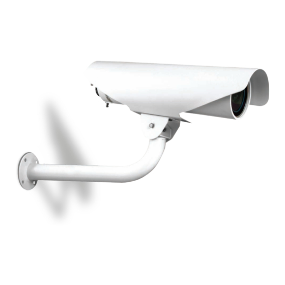
A P 1 6 C H 1 a n d A P 1 6 C H 2
Outdoor Tubular Pressurized Environmental Housing
Installation and Operation Instructions for the following models:
AP16CH1
Pressurized outdoor housing,115Vac input.
AP16CH2
16" dust-proof tubular housing, 24Vac input. Includes an integrated heater/defogger
MCL 16" (Maximum Camera Length)
Before attempting to connect or operate this product, please read these instructions completely.
www.videolarm.com
81-IN5264
01-11-2012
Advertisement
Table of Contents

Related Manuals for Moog Videolarm AP16CH1


Summary of Contents for Moog Videolarm AP16CH1
- Page 1 © 2011, Moog Videolarm, Inc. All Rights Reserved A P 1 6 C H 1 a n d A P 1 6 C H 2 Outdoor Tubular Pressurized Environmental Housing www.videolarm.com Installation and Operation Instructions for the following models: AP16CH1 Pressurized outdoor housing,115Vac input.
- Page 2 IMPORTANT SAFEGUARDS SAFETY PRECAUTIONS Read these instructions. Keep these instructions. CAUTION Heed all warnings RISK OF ELECTRIC SHOCK DO NOT OPEN Follow all instructions. Do not use this apparatus near water. CAUTION: TO REDUCE THE RISK OF Clean only with damp cloth. ELECTRIC SHOCK, DO NOT REMOVE COVER ( OR BACK).
- Page 3 1. NOTIFICATION OF CLAIMS: WARRANTY SERVICE: explanation of the claim shall be given promptly by Purchaser to Moog Videolarm. All claims for warranty service must be made within the warranty period. If after investigation Moog Videolarm determines the reported problem was not covered by the warranty, Purchaser shall pay Moog Videolarm for the cost of investigating the problem at its then prevailing per incident billable rate.
- Page 4 GENERAL INSTRUCTIONS: 2. Remove the cradle assembly by simultaneously grasping the rear handle and pulling the cradle assembly out of the housing. Be sure to keep the Use only with Class 2 Power Supply edges of the end caps clean and free of scratches. HARDWARE KIT 3. With the cradle removed from the housing place the camera/lens combination into the cradle assembly. Position the camera/lens 1mm (0.04- Cable Tie inch) away from the faceplate.The camera/lens is secured to the cradle with BHCS, 1/4-20 x 1/4-inch a 1⁄4-20 button head cap screw (BHCS) and the appropriate plastic spacer BHCS, 1/4-20 x 5/8-inch (Figure 2). BHCS, 1/4-20 x 3/4-inch BHCS, 1/4-20 x 1/2-inch BHCS, 1/4-20 x 3/8-inch BHCS, 1/4-20 x 11/4-inch 0.4 mm (0.016-inch) Plastic Spacer 1.65 mm (0.065-inch) Plastic Spacer 1/4-20 3.9 mm (0.154-inch) Plastic Spacer Spacers 7.4 mm (0.292-inch) Plastic Spacer 9.8 mm (0.385-inch) Plastic Spacer 3/8-inch NPT Plug Lock Washers Pull Seals Figure 2 1/4 - 20 Screws 4. Install camera into the HS9384-xHP housing utilizing the internal CAMERA INSTALLATION Attention: Installation should be performed by qualified service personnel...
- Page 5 CORROSION RESISTANT CONNECTOR 115 VAC Input, 24 VAC Camera All electrical connections are made via the single corrosion resistant The 115 VAC version uses an internal transformer (Figure 3). connector on the rear panel. A mating connector and crimp pins are supplied. 1. Connect the supply (115 VAC) to the primary flying leads of the The pins will accept wire from a minimum of 0.5 mm2 (20 AWG) to a transformer (white wire/pin 1, black wire/pin 6). Use the wire nuts provided maximum of 1.5 mm2 (16 AWG). Crimp the wire to the connector using an for this connection. appropriate crimp tool. Information on sync and video hookups is given in the 2. Connect the secondary flying leads (white/black striped wires/pins 7 and basic camera instructions. 12) to the camera’s 24 volt input 115 VAC VERSION To Camera To Heater/Defogger Figure 3 115V Hot Black White/ Black Network (Pin 1) Striped Network (Pin 2) 115 VAC 24 VAC Camera Network (Pin 3) Input...
- Page 6 EXPLODED VIEW Ref. No. Part Number Qty. Part Description Connector Kit 315 1592-001 16-Pin matching connector kit Cradle Assembly Kit – 315 3803-001 11 Cradle/Heater Assembly 16 Retaining Ring Ring Tongue Terminal 13 Ground Slide 10 M4 Phillips Head Screw 12 XXX Philips Head Screw Pull Seal 115 VAC Prewired Transformer Kit – 315 3804-001 315 3808-001 115 VAC Prewired Transformer 15 Rivet, 5⁄16-inch Transformer Insulator Housing Kit – 315 3807-001 14 Housing Silicone O-ring...
- Page 7 Product Registration/Warranty Thank you for choosing Moog Videolarm. We value your patronage and are solely committed to providing you with the highest quality products available and superior customer service. Should a problem arise, rest assure that Moog Videolarm stands behind its products by offering impressive warranty plans: 3 Years on all Housings, Poles, Power Supplies, and Accessories and 5 Years on camera systems (SView, QView, Warriors), and InfraRed Illuminators. Register Your Products Online Take a few moments and validate your purchase via the Online Product Registration Form at www.videolarm.com/productregistration.jsp Register your recent Moog Videolarm purchases and benefit from the following: • Simple and Trouble-Free RMA process • Added into customer database to receive product updates / news • Eliminate the need to archive original purchase documents: Receipts, Purchase Orders, etc…...
Need help?
Do you have a question about the AP16CH1 and is the answer not in the manual?
Questions and answers