Moog Videolarm PDW7CN-9 User Manual
Explosion-proof: purge/ pressurization unit
Hide thumbs
Also See for PDW7CN-9:
- Specification (2 pages) ,
- Installation and operation instructions manual (13 pages)
Table of Contents
Advertisement
Quick Links
www.videolarm.com
P D W 7 C S - 9
Explosion-Proof: Purge/ Pressurization Unit
PDW7CN-9
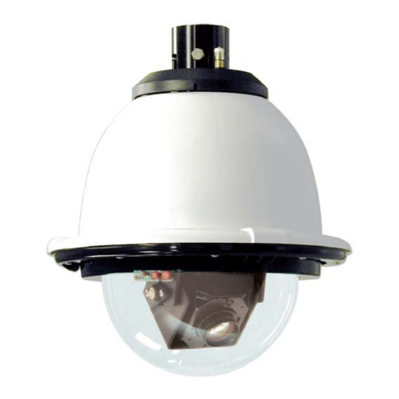
IP Network Ready 7" Explosion-Proof PurgeDome™ Outdoor
PTZ Camera Systems for Hazardous environments UL
approved for Class 1, Division II applications. Includes
Purging System and Lines. With 23x zoom Day/Night
camera, MPEG-4 & MJPEG video compression,
Full D1. Clear dome, with 24VAC input, heater/ blower
PDW7CS-9
Analog 7" Explosion Proof PurgeDome™ Outdoor PTZ Camera
Systems for Hazardous environments UL approved for
Class 1, Division II applications. Includes Purging System
and Lines. With 23x zoom Day/Night camera, MPEG-4 &
MJPEG video compression, Full D1. Clear dome, with
24VAC input, heater/ blower
B e fo r e a t t e m p t i n g t o c o n n e c t o r o p e r a t e t h i s p r o d u c t , p l e a s e r e a d t h e s e
i n s t r u c t i o n s c o m p l e t e l y. To b e u s e d w i t h t h e 8 1 - I N 5 4 0 9 I n s t r u c t i o n M a n u a l .
81-IN5410
01-30-2009
Advertisement
Table of Contents

Related Manuals for Moog Videolarm PDW7CN-9


Summary of Contents for Moog Videolarm PDW7CN-9
- Page 1 P D W 7 C S - 9 Explosion-Proof: Purge/ Pressurization Unit PDW7CN-9 IP Network Ready 7” Explosion-Proof PurgeDome™ Outdoor PTZ Camera Systems for Hazardous environments UL approved for Class 1, Division II applications. Includes Purging System and Lines. With 23x zoom Day/Night camera, MPEG-4 &...
- Page 2 IMPORTANT SAFEGUARDS Read these instructions. Keep these instructions. Heed all warnings Follow all instructions. Do not use this apparatus near water. Clean only with damp cloth. Do not block any of the ventilation openings. Install in accordance with the manufacturers instructions. Cable Runs- All cable runs must be within permissible distance.
- Page 3 1. NOTIFICATIONOF CLAIMS: WARRANTYSERVICE:If Purchaser believes that the Product is defective in material or workmanship, then written notice with an explanation of the claim shall be given promptly by Purchaser to Videolarm but all claims for warranty service must be made within the warranty period.
- Page 4 Content of Box Content of Box PROTECTED CAMERA ENCLOSURE SUPPLIED 1/4 “ & 3/8 ” POLY TUBING PAN / TILT DOME PURGE / PRESSURIZATION UNIT HARDWARE...
- Page 5 Unit is shipped with 100’ (max) flex tubing (3/8” & 1/4”) to connect enclosure to purge pressurized unit. 2 fitting are provided as shown in the diagrams. ENCLOSURE SUPPLY OUTLET (3/8 “ Push-in Fitting) ELECTRICAL ALARM WIRING CONDUIT AND SEAL (Customer Supplied) ...
-
Page 6: System Mounting
NOTES • To ensure adequate protective gas flow to the protected enclosure, all piping and tubing must be fully reamed. English • Precaution must be taken to prevent crimping and other damage to protective gas piping and tubing. Caution must be used when opening/closing swing panel to prevent tubing kinks. •... - Page 7 TUBING CONNECTION DIAGRAMS ENCLOSURE SUPPLY OUTLET TUBING CONNECTION DIAGRAMS PRESURE SWITCH PRIMARY REGULATOR SYSTEM SUPPLY INLET PEPPERL FUCHS PURGE/PRESSURIZATION UNIT PRESURE GAUGE [ENCLOSURE] SECONDARY REGULATOR ENCLOSURE REFERENCE INLET SYSTEM SUPPLY INLET DOME ATMOSPHERIC SDOEN OF WOSTOE SAFE HIGH REFERENCE ENCLOSURE PRESSURE REFERENCE PROTECTED CAMERA...
-
Page 8: Setup Procedure
CONNECTION SIZES, LENGTHS & BENDS GAS SUPPLY (System Supply) PURGE/PRESSURIZATION UNIT System Supply 3/8” OD SS Tubing Fully Reamed MAXIMUM: 20 ft / 10 bends SET-UP PROCEDURE • See supplied Model 1001A Installation and Operation Manual for Class I Purging Set-up. The use of a temporary SCFH flowmeter is unnecessary. -
Page 9: Wall Mount
WALL MOUNT: Attach unit securely to the wall mount using (4) 3/8” or 8mm hardware (not supplied). INPUT: (120VAC 1A 240VAC .5A) 110-120VAC INPUT The box is designed for either 120 or 240 VAC input single phase. Line (L) and Neutral (N) wires should be connected as marked on the board and plugged into the corresponding voltage for the input single phase. - Page 10 OUTPUT: (24VAC 84VA) Connect Housing Power Internal resettable fuses are supplied for the main 24VAC output lines. Do not connect heaters to camera output. The PB24 is not designed for 3 phase or 208V systems. Remove Pan/ Tilt from shipping carton. Install in base bracket in housing.
- Page 11 To install the dome align the tabs and twist counter clockwise to secure. Replacement Parts List Hand tighten the screws on the dome. Recommended torque 12 inches/lb (1.35Nm). Part Number RP65PT851200 PR25DCP71000 Description PAN TILT TRIM RING ASSEMBLY WITH CLEAR DOME...
- Page 12 S - V I E W PA N / T I LT Analog & IP Installation and Operation Supplement: B e fo r e a t t e m p t i n g t o c o n n e c t o r o p e r a t e t h i s p r o d u c t , 81-IN5409 p l e a s e r e a d t h e s e i n s t r u c t i o n s c o m p l e t e l y.
-
Page 13: Electrical Specifications
Electrical Specifications Class 2 Power Supply Only MODELS: 24 VAC S-view: Analog 13 WATTS S-view: IP 28 WATTS MODELS: 12VDC English S-view: Analog 13 WATTS S-view: IP 20 WATTS Fuente De Alimentación De la Clase 2 Solamente. MODELOS: 24 VAC S-vista: Análogo 13 VATIOS S-vista: IP... - Page 14 Remove Pan/Tilt from shipping carton. Install in base bracket in housing. • Quite Pan/Tilt del cartón del envío. Instale en soporte bajo en la cubierta. • Enlevez Pan/Tilt du carton d'expédition. Installez dans la parenthèse basse dans le logement. • Entfernen Sie Pan/Tilt vom Verschiffenkarton. Bringen Sie in niedrigen Haltewinkel im Gehäuse an.
- Page 15 • Al usar el regulador de Videolarm; para incorporar el menú; seleccione la cámara fotográfica que usted desea contro- lar. • En utilisant le contrôleur de Videolarm ; pour écrire le menu ; choisissez l'appareil-photo que vous souhaitez commander. • Wenn Videolarm Steuerpult verwendet wird; das Menü...
- Page 16 (IP) IP INSTRUCTIONS: The factory default IP address is : 192.168.0.200. • INSTRUCCIONES DEL IP: El IP address del defecto de la fábrica es: 192.168.0.200. • INSTRUCTIONS D'IP : Le IP address de défaut d'usine est : 192.168.0.200. • IP ANWEISUNGEN: Das Fabrikrückstellung IP address ist: 192.168.0.200.
- Page 17 Use Up & Down control on the controller to navigate through the menu. Pan left and right are used to enter sub menus. • Utilice para arriba y abajo controle en el regulador para navegar a través del menú. La cacerola a la izquierda e a la derecha se utiliza para incorporar menús secundarios.
- Page 18 When activated this will display camera’s address on the monitor. • Cuando está activado esto exhibirá la dirección de la cámara fotográfica en el monitor. • Quand activé ceci montrera l'adresse de l'appareil- photo sur le moniteur. • Wenn Sie diesem aktiviert werden, zeigt Adresse der Kamera auf dem Monitor an.
- Page 19 CAMERA / STABILIZATION Camera sub menu includes, image stabilization, day/night mode, shutter, backlight, AGC and digital zoom. Image stabilization is not a feature of all cameras. • El menú secundario de la cámara fotográfica incluye, estabilización de la imagen, modo de day/night, obturador, contraluz, AGC y zumbido digital. La estabilización de la imagen no es una característica de todas las cámaras fotográficas.
- Page 20 Llimit will “turn off” menu and allow you to position camera for left limit of zone. • Voluntad de Llimit "dar vuelta apagado" al menú y permitir que usted coloque la cámara fotográfica para el límite izquierdo de la zona. •...
- Page 21 Allow user to set dwell time for each stored preset. If presets have not been saved the dwell time for that preset will be displayed as “”. • Permita que el usuario fije el tiempo de detención para cada uno almacenada preestablecen.
- Page 22 1, 2, 3... To set a manually controlled pattern by joystick set Preset 80 (80,#, • Para fijar un patrón manualmente controlado por el sistema de la palanca de mando preestablezca 80 (80, #, • Pour placer un modèle manuellement commandé par l'ensemble de manche préréglez 80 (80, #, •...
- Page 23 ADDRESS ADDRESS ADDRESS...
- Page 24 ADDRESS ADDRESS ADDRESS ADDRESS...
- Page 25 ADDRESS ADDRESS ADDRESS ADDRESS...
-
Page 26: Replacement Parts List
Replacement Parts List Part No. RP6039mm1.8 RPVL2314 RP40CASL385 RPVL2315 RP605007 RPVL2316 RPVL2318 RPVL2320 RP605011 RP73CAVKS454 RP92WSFN11 RP605009 RP605008 RP95FSSR06 RP95FSSR07 RP605010 RPVL2312R1 RP76V385T RP76V385P RPVL2317 RPVL2321 Description Motor (2) Hub Bracket Slip Ring Assembly (2) 20T 80 Pitch Pulley (2) Bearing 90T Pan Pulley 60T Tilt Pulley... -
Page 27: Product Registration/Warranty
Product Registration/Warranty Thank you for choosing Videolarm. We value your patronage and are solely committed to providing you with only the highest quality products available with unmatched customer service levels that are second-to-none in the security industry. Should a problem arise, rest assure that Videolarm stands behind its products...
Need help?
Do you have a question about the PDW7CN-9 and is the answer not in the manual?
Questions and answers