Table of Contents
Advertisement
Quick Links
www.videolarm.com
F D W 7 5
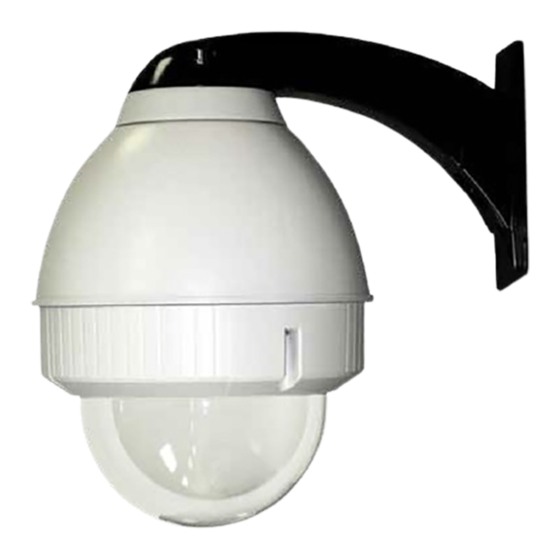
Fusion Dome (Outdoor Wall Mount with Housing)
Installation and Operation Instructions for the following models:
FDW75C2N
IP Network Ready 7" Outdoor dome hsg w/wall mount, clear dome, w/24Vac input, heater/
blower, fan an IP Network PTZ camera, 120 to 24Vac transformer.
FDP75C2N
IP Network Ready 7" Outdoor dome hsg w/pendant mount, clear dome, w/24Vac input, heater/
blower, fan an IP Network PTZ camera,120 to 24Vac transformer.
IFDW75CN
IP Network Ready 7" Indoor dome hsg w/wall mount, clear dome, w/24Vac input, heater/
blower, fan an IP Network PTZ camera, 120 to 24Vac transformer.
IFDP75CN
IP Network Ready 7" Indoor dome hsg w/pendant mount, clear dome, w/24Vac input, heater/
blower, fan an IP Network PTZ camera,120 to 24Vac transformer.
FDW75C2NE
IP Network Ready 7" Outdoor dome hsg w/wall mount, clear dome, w/24Vac input, heater/
blower, fan an IP Network PTZ camera. (European Model)
FDP75C2NE
IP Network Ready 7" Outdoor dome hsg w/pendant mount, clear dome, w/24Vac input, heater/
blower, fan an IP Network PTZ camera. (European Model)
FDW75C2N/AC
IP Network Ready 7" Outdoor dome hsg w/wall mount, clear acrylic dome, w/24Vac input, heater/
blower, fan an IP Network PTZ camera, 120 to 24Vac transformer.
FDP75C2N/AC
IP Network Ready 7" Outdoor dome hsg w/pendant mount, clear dome, w/24Vac input, heater/
blower, fan an IP Network PTZ camera,120 to 24Vac transformer.
B e fo r e a t t e m p t i n g t o c o n n e c t o r o p e r a t e t h i s p r o d u c t ,
p l e a s e r e a d t h e s e i n s t r u c t i o n s c o m p l e t e l y.
81-IN5358R1
Advertisement
Table of Contents

Subscribe to Our Youtube Channel
Related Manuals for Moog Videolarm FDP75C2N/AX


Summary of Contents for Moog Videolarm FDP75C2N/AX
- Page 1 F D W 7 5 Fusion Dome (Outdoor Wall Mount with Housing) Installation and Operation Instructions for the following models: FDW75C2N IP Network Ready 7” Outdoor dome hsg w/wall mount, clear dome, w/24Vac input, heater/ blower, fan an IP Network PTZ camera, 120 to 24Vac transformer. FDP75C2N IP Network Ready 7” Outdoor dome hsg w/pendant mount, clear dome, w/24Vac input, heater/ blower, fan an IP Network PTZ camera,120 to 24Vac transformer.
- Page 2 IMPORTANT SAFEGUARDS IMPORTANT SAFEGUARDS Read these instructions. 1 Read Instructions - All the safety and operating Keep these instructions. instructions should be read before the unit is operated. Heed all warnings 2 Retain Instructions - The safety and operating Follow all instructions. instructions should be retained for future Do not use this apparatus near water.
- Page 3 1. NOTIFICATION OF CLAIMS: WARRANTY SERVICE: If Purchaser believes that the Product is defective in material or workmanship, then written notice with an explanation of the claim shall be given promptly by Purchaser to Videolarm but all claims for warranty service must be made within the warranty period.
-
Page 4: Electrical Specifications
Electrical Specifications Power 24VAC Class 2 Only 24 VAC 26 Watts Accessories: Heater: 25 Watts, Blower: 1 Watt Camera Power: Tools Required: .100” Flat Head Screwdriver English 24 VAC 26 vatios Accesorios: Calentador: 25 Vatios, Soplador: 1 vatio Energía De la Cámara fotográfica: Las Herramientas Requirieron: Destornillador Principal Plano Del 100". - Page 5 Securely mount unit to wall or to appropriate adapter bracket. • Monte con seguridad la unidad a la pared o al soporte apropiado del adaptador. • Montez solidement l'unité au mur ou à la parenthèse appropriée d'adapteur. • Bringen Sie sicher Maßeinheit zur Wand oder zum passenden Adapterhaltewinkel an.
- Page 6 Securely mount bracket to wall. Pull wiring through bracket and position grommet as shown. • Con seguridad soporte del montaje a emparedar. Tire del cableado a través del soporte y del ojal de la posición según lo demostrado. • Solidement parenthèse de bâti à murer. Tirez le câblage par la parenthèse et le canon isolant de position comme montré.
- Page 7 Loop the lanyard over the set screw to temporarily hold housing. • Coloque el acollador sobre el tornillo de presión para celebrar temporalmente la cubierta. • Faites une boucle la lanière au-dessus de la vis de réglage pour tenir temporairement le logement. •...
- Page 8 Make the appropriate male and female connections. Indoor model does not include pre-run cables. • Haga las conexiones masculinas y femeninas apropiadas. El modelo de interior no incluye pre-funciona los cables. • Établissez les rapports masculins et femelles appropriés. Le modèle d'intérieur n'inclut pas pré-courent des câbles. •...
-
Page 9: Axis 214
Axis 213 2539 Mounting Plate Mounting Hole Install the camera to the mounting plate with (2) #10 screws and lock washers provided. Place (3) #8x3/8” screws on the spacers and align the mounting slots. Slide on plate and camera then secure. •... - Page 10 Axis 215 MOUNTING HOLE Install the camera to the mounting plate with (4) #8 screws and lock washers provided. Place (3) #8x3/8” screws on the spacers and align the mounting slots. Slide on plate and camera then secure. • Instale la cámara fotográfica a la placa de montaje con (4) los tornillos #8 y las arandelas de cerradura proporcionadas. Coloque los tornillos de (3) del # 8x3/8"en los espaciadores y alinee las ranuras de montaje.
- Page 11 Axis 231D/232D Mounting Hole Mounting Hole Use the (3) keyhole slots indicated above. • Utilice (3) las ranuras del ojo de la cerradura indicadas arriba. • Employez (3) les fentes de trou de la serrure indiquées ci-dessus. • Benutzen Sie die (3) Schlüssellochschlitze, die oben angezeigt werden.
- Page 12 Remove the power board located inside the housing. Attach the connection module as shown. This is what the typical path of illumination will look like with the setting at 30 degrees. Attach this assembly to the housing using (1) 6-32x3/8” screw and star washer. •...
- Page 13 Axis 233D Mounting Hole Mounting Hole Use the holes indicated above to mount the camera. • Utilice los agujeros indicados arriba para montar la cámara fotográfica. • Employez les trous indiqués ci-dessus pour monter l'appareil-photo. • Benutzen Sie die Bohrungen, die oben angezeigt werden, um die Kamera anzubringen.
- Page 14 Mount the Axis 233D camera bracket and quick release plate using the additional spacers from This is what the typical path of illumination will look like with the setting at 30 degrees. the hardware packet. • Monte el soporte de la cámara fotográfica del eje 233D y la placa rápida del lanzamiento usando los espaciadores adicionales del paquete del hardware.
- Page 15 Canon VB-C10R 2539 Mounting Plate Mounting Hole Mount the camera to the 2539 plate using the provided hardware. Place (3) 8 x 32 x 3/8 Phillips head screws on the top of the spacer as shown above. Slide plate in and secure. Monte la cámara fotográfica a la placa 2539 usando el hardware proporcionado.
-
Page 16: Elmo Ptc-200C
Canon VC-C4R/VC-C50IR 2539 Mounting Plate Mounting Hole Mount the camera to the 2539 plate using the provided hardware. Place (3) 8 x 32 x 3/8 Phillips head screws on the top of the spacer as shown above. Slide plate in and secure. •... -
Page 17: Elmo Ptc-201
Elmo PTC-201 Mounting Hole Place the camera onto the quick release bracket using the (4) metric 3M Phillips head screws provided. Place the screws on the spacers. Slide on the plate and camera then secure. • Coloque la cámara fotográfica sobre el soporte rápido del lanzamiento usando (4) los tornillos principales los 3M Phillips métricos proporcionados. -
Page 18: Elmo Ptc-401
Elmo PTC-401 Mounting Hole Attach quick release bracket to mounting plate using (4) #8 screws and star washer. Complete assembly as shown, then secure camera to the quick release plate. • Una el soporte rápido del lanzamiento a la placa de montaje usando (4) los tornillos #8 y la arandela de la estrella. Termine a asamblea como cámara fotográfica demostrada, después segura a la placa rápida del lanzamiento. - Page 19 JVC VN-C625U / TK-625U 2630 Mounting Plate Remove the cover and detach bracket. Attach (4) 1” spacers to the 2630 mounting plate and (4) to the main bracket. Place (3) 8x32x3/8” Phillips screws onto the spacers. Secure plate and camera. •...
- Page 20 Panasonic BB-HCM381/580/581 & KX-HMC280 2539 Mounting Plate Install the camera to the bracket with the 1/4x20” washer and lock washer. Place (3) 8x32x3/8” screws on the spacers. Slide on the camera and plate then secure. • Instale la cámara fotográfica al soporte con la arandela del 1/4x20"y la arandela de cerradura. Coloque (3) los tornillos del 8x32x3/8"...
-
Page 21: Sony Sncrz25
Sony SNCRZ25 2539 Mounting Plate Attach bracket with (1) 1/4x20 bolt, washer and lock washer and (2) 3mm x 8mm Phillip head screws and lockwashers. Place the screws on the spacers. Slide on the plate and camera then secure. • Instale la cámara fotográfica al soporte con (3) los tornillos, las tuercas y las arandelas principales el 8x32x.5"planos. Coloque (3) 8x32x3/8"screws en los espaciadores. -
Page 22: Sony Sncrz50
Sony SNCRZ50 2539 Mounting Plate Attach bracket with 3mm x 8mm bolts and lock washers. Place (3) 8x32x3/8”screws on the spacers. Slide on the plate and camera then secure. • Una el soporte con los pernos de 3m m x de 8m m y las arandelas de cerradura. Coloque (3) 8x32x3/8"screws en los espaciadores. - Page 23 Loop the lanyard around the tab inside the housing. • Coloque el acollador alrededor de la lengüeta dentro de la cubierta. • Faites une boucle la lanière autour de l'étiquette à l'intérieur du logement. • Schlingen Sie die Abzuglinie um den Vorsprung innerhalb des Gehäuses.
-
Page 24: Replacement Parts List
Replacement Parts List 1 1 1 Part Number RPFD7501 FD7T FD7C RPFD703 RPFD072 RPFD080 RPFD060 RPFD050 (MODEL FD7HB) RPRH707 (MODEL FD7NHB) RPFD040 RPFD709 RPFD2612 WM10 RPNET02 RPNET04 SD0170 SD0180 SD0160 RPPKE1100 RPPKH2090 RPPKH2071 RPPKE1125 RPTRAN02 FDW75 Description LOWER TRIM RING TINTED REPLACEMENT CAPSULE CLEAR REPLACEMENT CAPSULE DOME CLAMPING BRACKET... -
Page 25: Product Registration/Warranty
Product Registration/Warranty Thank you for choosing Videolarm. We value your patronage and are solely committed to providing you with only the highest quality products available with unmatched customer service levels that are second-to-none in the security industry. Should a problem arise, rest assure that Videolarm stands behind its products...
Need help?
Do you have a question about the FDP75C2N/AX and is the answer not in the manual?
Questions and answers