Table of Contents
Advertisement
Quick Links
Download this manual
See also:
Setup Manual
Advertisement
Table of Contents

Subscribe to Our Youtube Channel
Related Manuals for Toa C-CC714 NT


Summary of Contents for Toa C-CC714 NT
- Page 1 INSTALLATION MANUAL OUTDOOR COMBINATION CAMERA C-CC714 NT C-CC714 PL C-CC764 NT C-CC764 PL C-CC774 NT C-CC774 PL Thank you for purchasing TOA’s Outdoor Combination Camera. Please carefully follow the instructions in this manual to ensure long, trouble-free use of your equipment.
-
Page 2: Table Of Contents
TABLE OF CONTENTS 1. SAFETY PRECAUTIONS ................3 2. GENERAL DESCRIPTION ................5 3. FEATURES ......................5 4. HANDLING PRECAUTIONS ................6 5. NOMENCLATURE ..................... 8 6. CONNECTIONS 6.1. Precautions When Installing the Camera ............10 6.2. Camera Control Connector Connection (RS-485) .......... 11 7. -
Page 3: Safety Precautions
1. SAFETY PRECAUTIONS • Be sure to read the instructions in this section carefully before use. • Make sure to observe the instructions in this manual as the conventions of safety symbols and messages regarded as very important precautions are included. •... - Page 4 • Contact your TOA dealer as to the cleaning. If dust is allowed to accumulate in the unit over a long period of time, a fire or damage to the unit may result.
-
Page 5: General Description
2. GENERAL DESCRIPTION TOA’s dome-type color cameras combine with a high-speed camera drive that permits one 360-degree horizontal rotation per second and a 35x (C-CC774), a 23x (C-CC764) or a 22x (C-CC714) optical zoom lens. Up to 255 arbitrary positions can be preset and such preset positions can be instantaneously repeated. The systems also feature a 12x electronic zoom, timer, and tracing, while the C-CC764 and C-CC774 offer additional functions that include a motion detector, auto flip, black &... -
Page 6: Handling Precautions
4. HANDLING PRECAUTIONS • Noise may appear on the monitor or preset camera positions may deviate with prolonged camera use. In such cases, use the camera’s refresh function to automatically refresh settings and reestablish the home position once a day or week, thus allowing any position deviation to be corrected. When correcting manually, initialize the camera from the remote controller. - Page 7 • Modifications Any modifications made to this device that are not approved by TOA Corporation may void the authority granted to the user by the FCC to operate this equipment. Underwriters Laboratories Inc. (UL) has not tested the performance or reliability of the security aspects of this product.
-
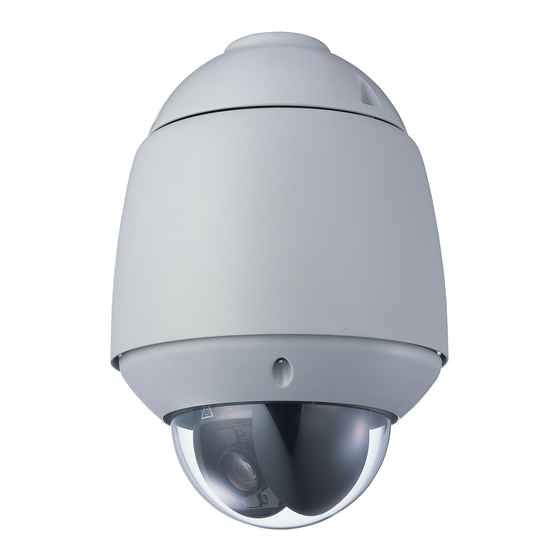
Page 8: Nomenclature
5. NOMENCLATURE [ Appearance ] [ Camera Unit Appearance ] [ Camera Unit Bottom ] [ Housing Appearance ] [ Camera Unit Top ] [ Housing Bottom ]... - Page 9 [ C-BC711W Wall Mounting Bracket (optional) ] [ C-BC711P Suspension Bracket (optional) ] [ C-BC711PM Pole Mounting Bracket (optional) ] (1) Top cover (14) COM LED* (2) Safety wire for housing (15) COM PORT* (3) Housing adaptor (16) DIP switch (SW1) (4) Safety screw (17) DIP switch (SW2) (5) Dome cover...
-
Page 10: Connections
6. CONNECTIONS Power cable Connects to the power supply. (24V AC 50/60 Hz) Alarm input/output terminal (No. 1 - 5) Connects to the sensor of no-voltage make contact or the external equipment that can be controlled using the auxiliary output. Camera control terminal (No. -
Page 11: Camera Control Connector Connection (Rs-485)
6.2. Camera Control Connector Connection (RS-485) • Connect terminals (+) and (–) of the C-RM500 Remote Controller or the C-IF500 Interface Unit to the camera's terminals (+) (terminal No. 8) and (–) (terminal No. 7), respectively. • Connect the camera's terminals (+) and (–) to the next camera's terminals (+) and (–) in order. Notes •... -
Page 12: Dip Switch Settings
7.3. Dip Switch Settings DIP SW1 DIP SW2 DIP SW3 DIP SW1 DIP SW2 DIP SW3 Communication speed setting Camera address setting switch 1 No.1 Firmware update switch 1 switch 1 Communication speed setting Camera address setting switch 2 No.2 Firmware update switch 2 switch 2 Camera address setting switch 3... -
Page 13: Communication Speed Setting Switch (Dip Switch 2: No. 1 - 2)
7.3.2. Communication Speed Setting Switch (DIP switch 2: No. 1 – 2) Check to be sure that the communication speed set here is the same as that of the Remote Controller. When changing the speed, change settings of all cameras and Remote Controller within the system. (Factory setting: 38,400 bps.) No.1 No.2... - Page 14 [ Camera address setting switch: 1 – 64 ] DIP switch 1 DIP switch 1 DIP switch 1 DIP switch 1...
- Page 15 [ Camera address setting switch: 65 – 128 ] DIP switch 1 DIP switch 1 DIP switch 1 DIP switch 1...
- Page 16 [ Camera address setting switch: 129 – 192 ] DIP switch 1 DIP switch 1 DIP switch 1 DIP switch 1...
- Page 17 [ Camera address setting switch: 193 – 255 ] DIP switch 1 DIP switch 1 DIP switch 1 DIP switch 1...
-
Page 18: Installation
8. INSTALLATION The Combination Camera weight 4.4 kg. Select the heavy-duty mounting surface that can structurally support the weight of the WARNING camera. Doing otherwise may result in the unit falling and possibly causing personal injury. 8.1. About Installation • Mount the camera to a heavy-duty wall surface using the optional C-BC711W Wall Mounting Bracket. •... -
Page 19: Wall Mounting Bracket Installation
8.3. Wall Mounting Bracket Installation Use the optional C-BC711W Wall Mounting Bracket. Notes • Check to be sure that wall surface can structurally support the weight of the camera and mounting bracket. • Bolts, nuts and washers are not supplied with the bracket. Use bolts, nuts and washers that are appropriate for the wall's structure and composition. -
Page 20: Attaching Housing And Camera Unit To Wall Mounting Bracket
8.4. Attaching Housing and Camera Unit to Wall Mounting Bracket 1. Loosen 2 safety screws. Safety screw Safety wire Safety screw Housing 2. Run the safety wire through the top cover, then hang the hook to the mounting bracket. 3. Run the top cover through the pipe, then connect cables. Wall surface Top cover Safety wire... - Page 21 4. After confirming the housing direction, push the housing up, then tighten 2 safety screws. Safety screw Top cover Align the Safety screw hole positions. Housing 5. Using the 3 supplied camera mounting screws M5 x 12, attach the housing unit to pipe. Tighten 3 screws equally and ensure that no parts rattle.
- Page 22 6. Using the supplied 3 hexagon socket screws, attach the top cover 1 to the housing. Hexagon socket screw M4 x 8 (supplied with) Hexagon socket screw M4 x 8 (supplied with) 7. Connect the safety wire to the housing projection, then attach the camera unit. Note: Align mark of the camera unit with that of the housing when attaching the camera unit to the housing.
- Page 23 Note Insert the camera unit in an oblique direction in the order of 1 to 2 keeping away from the duct of the housing. mark Duct 8. Make the camera unit in horizontal position and push it straight up closely to the housing. Cross sectional view of the housing Camera unit...
- Page 24 Note Do not allow the safety wire to protrude from the compartment of the camera unit. Damage may be caused to the wire if it protrudes. Safety wire protrudes from the compartment. Safety wire does not protrude from the compartment. Note When mounting the camera unit to the housing, mount it straight till it is attached to the housing correctly.
- Page 25 9. Rotate the camera unit until it locks into place. 10. Tighten 2 camera unit mounting screws to attach the camera unit to the base unit. Camera unit mounting screw Camera unit mounting screw 11. Attach the dome cover. Slide down the dome cover’s screw head through the housing suspension fitting’s slot. Hang...
- Page 26 12. Align the dome cover’s 4 screws with the hexagon head sleeves inside the housing. Note Be sure to attach the dome cover after sliding down its screw head through the housing suspension fitting’s slot so that the dome cover can be attached securely to the housing. Hexagon head Hexagon head sleeve...
-
Page 27: Pole Mounting Bracket Installation
8.5. Pole Mounting Bracket Installation The optional C-BC711PM Pole Mounting Bracket, C-BC711W Wall Mounting Bracket and YS-60B Mounting Band are required to mount the camera on a pole. Note Those mounting brackets and band can be installed on a pole having a mounting pipe diameter of 90 - 340 mm. -
Page 28: Suspension Bracket Installation
8.6. Suspension Bracket Installation The C-BC711P Suspension Bracket is required to suspend the camera from a ceiling. Note Mount the bracket to a concrete wall or robustly constructed wall surface that can sufficiently withstand the weight of the units. 1. Make a cable entry hole of ø 50 – 100 mm on a ceiling. Hole diameter: ø... -
Page 29: System Examples
9. SYSTEM EXAMPLES [ RS-485 Communications line control ] Combination camera Monitor TV Multi-switcher Outdoor combination camera Dedicated Remote controller Note Combination cameras and outdoor combination cameras can be used in free combinations. When a camera (fixed installation* ) is used in combinations, the corresponding camera screens can be controlled by the switcher only. -
Page 30: Specifications
10. SPECIFICATIONS Model C-CC714 NT C-CC714 PL Power Source 24 V AC, 50/ 60 Hz (2P loose end) Power Consumption 10 W (normal operation), 80 W max.(2.8 A max) Control RS-485 communications system (new protocol compatible) Video Output VBS 1.0 V(p-p), 75 Ω, BNC-R jack... - Page 31 C-CC764 NT C-CC764 PL Model 24 V AC, 50/ 60 Hz (2P loose end) Power Source 10 W (normal operation), 80 W max.(2.8 A max) Power Consumption RS-485 communications system (new protocol compatible) Control VBS 1.0 V(p-p), 75 Ω, BNC-R jack Video Output RS-485 camera control connector, multi-pair cable 8P loose end (3P of8 P) Camera Control Terminal...
- Page 32 Model C-CC774 NT Power Source 24 V AC, 50/ 60 Hz (2P loose end) Power Consumption 10 W (normal operation), 80 W max. (2.8 A max) Control RS-485 communications system (new protocol compatible) Video Output VBS 1.0 V(p-p), 75 Ω, BNC-R jack Camera Control Terminal RS-485 camera control connector, multi-pair cable 8P loose end (3P of 8P) Alarm Input...
- Page 33 Model C-CC774 PL Power Source 24 V AC, 50/ 60 Hz (2P loose end) Power Consumption 10 W (normal operation), 80 W max. (2.8 A max) Control RS-485 communications system (new protocol compatible) Video Output VBS 1.0 V(p-p), 75 Ω, BNC-R jack Camera Control Terminal RS-485 camera control connector, multi-pair cable 8P loose end (3P of 8P) Alarm Input...
-
Page 34: Accessories
• Accessories CD-R (CAMERA CONTROLLER Software, installation manual) ..1 Hexagon socket screw M4 x 8 ............3 • Optional Products Wall Mounting Bracket: C-BC711W Suspension Bracket: C-BC711P Pole Mounting Bracket: C-BC711PM Mounting Band: YS-60B Smoked dome cover: C-A711DM... - Page 36 1 3 3 - 0 5 - 4 0 6 - 0 A...
Need help?
Do you have a question about the C-CC714 NT and is the answer not in the manual?
Questions and answers