Table of Contents
Advertisement
Quick Links
Download this manual
See also:
Setup Manual
COMBINATION CAMERA
For details regarding camera setting procedure, refer to the setting manual in the
manual CD supplied with the unit.
Thank you for purchasing TOA's Combination Camera. Please carefully follow the instructions in this
manual to ensure long, trouble-free use of your equipment.
INSTALLATION MANUAL
C-CC704 CU
Advertisement
Table of Contents

Related Manuals for Toa C-CC704 CU


Summary of Contents for Toa C-CC704 CU
- Page 1 For details regarding camera setting procedure, refer to the setting manual in the manual CD supplied with the unit. Thank you for purchasing TOA’s Combination Camera. Please carefully follow the instructions in this manual to ensure long, trouble-free use of your equipment.
-
Page 2: Table Of Contents
TABLE OF CONTENTS 1. SAFETY PRECAUTIONS ................3 2. GENERAL DESCRIPTION ................6 3. FEATURES ......................6 4. HANDLING PRECAUTIONS ................6 5. NOMENCLATURE ..................... 8 6. INSTALLATION PRECAUTIONS 6.1. Dip Switch Settings ................... 9 6.1.1. Camera address setting switch ( No. 1 – No. 6 ) ........9 6.1.2. -
Page 3: Safety Precautions
1. SAFETY PRECAUTIONS • Before installation or use, be sure to carefully read all the instructions in this section for correct and safe operation. • Make sure to observe the instructions in this manual as the conventions of safety symbols and messages regarded as very important precautions are included. - Page 4 • Contact your TOA dealer as to the cleaning. If dust is allowed to accumulate in the unit over a long period of time, a fire or damage to the unit may result.
- Page 5 Modifications Any modifications made to this device that are not approved by TOA Corporation may void the authority granted to the user by the FCC to operate this equipment.
-
Page 6: General Description
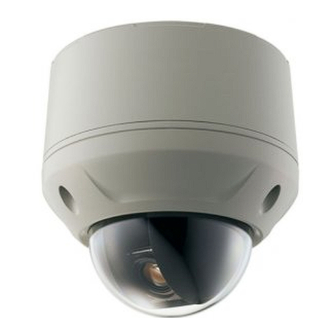
2. GENERAL DESCRIPTION The dome-type color camera allows 360-degree horizontal rotation and combines with a high speed camera drive that permits 200-degree horizontal rotation and vertical tilting per second and a 10x optical zoom lens. Up to 64 arbitrary positions can be preset and such preset positions can be instantaneously repeated. It also offers functions such as a 12x electronic zoom, trace, and tour. - Page 7 • Avoid installing the unit on sea or shore, in dusty locations, or in locations exposed to corrosive gas, herbicides or other sprayed liquid chemicals such as pools, or extraordinary combustible conditions. • To prevent camera unit fall, connect the supplied safety wire to the case when installing the camera unit to the case.
-
Page 8: Nomenclature
5. NOMENCLATURE [ Back side of the case ] [ Top view of the camera unit ] Case Power supply connector Camera unit DIP switch Dome cover Pipe receptacle cover Input/output connector... -
Page 9: Installation Precautions
6. INSTALLATION PRECAUTIONS The unit weighs 1.8 kg. Select the heavy-duty mounting surface that can structurally support the total weight of the unit and bracket. Doing WARNING otherwise may result in the unit falling and possibly causing personal injury. Notes •... - Page 10 [ Camera address setting switch: 1 – 63 ] DIP switch DIP switch DIP switch DIP switch 9 10 9 10 9 10 9 10 9 10 9 10 9 10 9 10 9 10 9 10 9 10 9 10 9 10 9 10 9 10...
-
Page 11: Connections
7. CONNECTIONS [ Power supply connector ] Power input terminal Connect this terminal to 24 V AC. ( 50/60 Hz ) [ Input/output connector ] ( No. 1 and No. 2 ) Video output terminal Connect to the video input terminal of the monitor, digital video recorder, or multi-switcher. -
Page 12: Note On Camera Installation
7.2. Note on Camera Installation • Be sure to seal and insulate each connection of the video output cable, power supply cable, control cable, and alarm cable with each corresponding cable from the other equipment using the waterproof tape. Perform the wiring paying attention not to touch the peripheral metal parts. -
Page 13: Installation
8. INSTALLATION 8.1. Cable Routing from the Ceiling Note: Be sure to switch off the power when installing the camera. 1. Make a hole in the ceiling panel, then pull out the cable through it. 2. Run the cables extending from the ceiling through the cable entry hole on the upper side of the case, then secure the case to the ceiling. - Page 14 3. When installing the camera, ensure that ceiling is strong enough to withstand the camera load. Note: Be sure to seal and insulate each connection of the cable with waterproof tape. Composite cable 4. Remove the buffer material for transportation from the camera unit. Buffer material Camera Unit...
- Page 15 5. Attach the dome cover to the camera unit. Dome cover fixing screw ( accessory ) Camera unit Dome cover 6. Perform DIP switch settings. For switch settings, refer to p. 9. 7. Connect the safety wire secured to the camera unit to the case. Safety wire...
- Page 16 8. Connect the composite cable connected to the cables extended from the ceiling to the camera unit. Composite cable 9. Secure the camera section ( camera unit + dome cover ) to the case using the supplied TORX wrench. Align the positioning marks on both rear sides. Align the positioning marks.
-
Page 17: Open Wring From The Camera's Side
8.2. Open Wiring from the Camera's Side 1. Detach the pipe receptacle cover on the camera side, then attach it to the case's top surface. Attach Detach 2. Wrap two or more turns of sealing tape around the pipe's threaded section, then screw the pipe into the camera's threaded receptacle. -
Page 18: System Examples
9. SYSTEM EXAMPLES 9.1. Connection Example to the Digital Video Recorder Monitor Combination camera Digital video recorder Combination camera Remote controller 9.2. Connection Example to the Multi-switcher Monitor Combination camera Multi-switcher Combination camera Remote controller Note It is possible to use the Combination Cameras in any combination. When using the Combination Cameras in combination with the fixed cameras, only screen control is possible by the switcher as for the fixed camera channels. -
Page 19: Specifications
10. SPECIFICATIONS Power Source 24 V AC, 50/ 60 Hz Power Consumption 11 W RS-485 communications system ( applicable protocol: Type A , Type B ) Control Video Output VBS 1.0 V(p-p), 75 Ω Camera Control Terminal RS-485 camera control connector Alarm Input 4-channels, no-voltage make contact input, open voltage: 5 V DC, short-circuit current: 8 mA or less ( settable alarm action ) -
Page 20: Accessories
Dome cover fixing screw M4 x 10 ....3 Composite cable ........1 TORX wrench ..........1 Sealing tape ..........1 • Optional products Wall Mounting Bracket: C-BC704W Pole Mounting Bracket: C-BC771PM Flush Ceiling Mounting Bracket: C-BC704U Pendant adapter: C-BC704PB Mounting Band: YS-60B URL: http://www.toa.jp/ 133-22-209-4C...
Need help?
Do you have a question about the C-CC704 CU and is the answer not in the manual?
Questions and answers