Table of Contents
Advertisement
Quick Links
Download this manual
See also:
Installation Manual
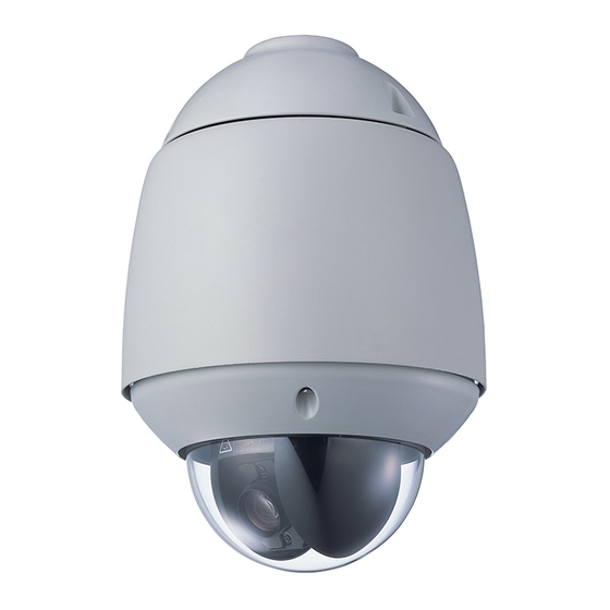
COMBINATION CAMERA
OUTDOOR COMBINATION
CAMERA
Thank you for your purchasing TOA's Combination Camera. Please carefully follow the instructions in
this manual to ensure long, trouble-free use of your equipment.
C-CC514 NT, C-CC514 PL
C-CC564 NT, C-CC564 PL
C-CC574 NT, C-CC574 PL
C-CC714 NT, C-CC714 PL
C-CC764 NT, C-CC764 PL
C-CC774 NT, C-CC774 PL
SETUP MANUAL
Advertisement
Table of Contents

Related Manuals for Toa C-CC514 NT


Summary of Contents for Toa C-CC514 NT
- Page 1 C-CC574 NT, C-CC574 PL C-CC714 NT, C-CC714 PL OUTDOOR COMBINATION C-CC764 NT, C-CC764 PL CAMERA C-CC774 NT, C-CC774 PL Thank you for your purchasing TOA’s Combination Camera. Please carefully follow the instructions in this manual to ensure long, trouble-free use of your equipment.
-
Page 2: Table Of Contents
TABLE OF CONTENTS 1. SETTING ITEMS GUIDE ................5 2. BEFORE SETTING 2.1. Address Display When Turning Power On ......... 2.2. Keys Used to Settings ..............2.3. Setting Basic Operation ............. 3. ENTERING CAMERA MENU SCREEN 3.1. Selecting the Language ............4. - Page 3 6. CAMERA CHARACTERISTICS SETTINGS .......... 31 6.1. Setting the White Balance ............6.2. Setting the Backlight Compensation ........6.3. Adjusting the Brightness ............6.4. Setting the Day and Night ......( C-CC564, C-CC574, C-CC764 and C-CC774 only ) 6.5. Setting the Auto Focus ............. 6.6.
- Page 4 9. CONTACT OUTPUT SETTINGS 9.1. AUX 1 Setting ................9.2. AUX 2 Setting ........(C-CC564 and C-CC574 only) 10. TIMER SETTINGS 10.1. Program Settings ..............10.1.1. Erasing Timer program ..............62 10.2. Time Display Selection ............10.3. Date Display Setting ............... 10.4.
-
Page 5: Setting Items Guide
1. SETTING ITEMS GUIDE The camera menu screens are comprised of the following setting item screens. MAIN MENU (p.10) CAMERA MENU Setting Item Programs the camera position (camera direction), displays (p.11) PRESET setting status, and performs reset. MEMORY * (p.11) Programs the camera position. - Page 6 From previous page Electronic Image Stabilization settings. EIS * (p.39) Sensitivity-Up selection. SENSITIVITY * (p.39) Return each item on the camera setting screen to RESET ( CAM SETTING ) (p.40) the factory default status. Sets automatic operation of Auto Pan, Preset sequence, Trace (p.40) AUTO MODE and Tour.
- Page 7 Can be only set for the C-CC574 and C-CC774. Note The name of article of the text is displayed as follows; C-CC514: C-CC514 NT or C-CC514 PL C-CC564: C-CC564 NT or C-CC564 PL C-CC574: C-CC574 NT or C-CC574 PL C-CC714: C-CC714 NT or C-CC714 PL...
-
Page 8: Before Setting
2. BEFORE SETTING 2.1. Address Display When Turning Power On When the camera’s power is turned on, the camera performs the initial operation (initializing operation) and simultaneously the camera address appears on the monitor. After the completion of initial operation and peripheral device connections, the camera can be controlled and the camera address screen will disappear. -
Page 9: Setting Basic Operation
2.3. Setting Basic Operation Menu screen to be displayed and the operation slightly differ depending on the connected equipment, however there is no difference in basic operation. More particularly, refer to the instruction manual, operation manual or set up manual enclosed with each equipment. -
Page 10: Entering Camera Menu Screen
3. ENTERING CAMERA MENU SCREEN 1. Press the Menu key. (When a password is required, enter it with the numerical keypad.) The menu screen Menu is displayed on the remote controller’s liquid crystal display. O P E R A T I O N M O D E 2. -
Page 11: Setting Presets
4. SETTING PRESETS Settings such as camera direction, lens angular field of view, and focus can be preset in advance. Up to 255 positions can be set. 4.1. Entering Presets Into the Memory Note Positions cannot be preset in the electronic zoom range 37) or in flip mode 68). - Page 12 4. Press the Set key. The position setting screen (the selected camera image) is * * * - * * * displayed. S E T T I N G Note “ – ” on the first line of the Setting screen indicates the camera number on the left and the position number on the right.
-
Page 13: Global Preset Memory Correction
4.2. Global Preset Memory Correction This function simultaneously resets all preset camera panning positions. The deviation of one camera position is measured, based on which all other positions are globally corrected. When performing this global correction, use the position on the telescope side whenever possible. 1. -
Page 14: Preset Memory Reset
4.3. Preset Memory Reset 1. Select “PRESET” on the camera menu screen and press the Set key. P R E S E T The Preset Settings screen is displayed. M E M O R Y R E A D J U S T A L L P O S P O S * * * M E M O R Y R E S E T... -
Page 15: Preset Memory All Reset
4.4. Preset Memory All Reset Deletes all preset position data. 1. Select “PRESET” on the camera menu screen and press the Set key. The Preset Settings screen is displayed. 2. Select “MEMORY ALL RESET” with the joystick and press the Set key. -
Page 16: Home Setting
4.6. Home Setting Designate the program the camera automatically returns to. 1. Select “PRESET” on the camera menu screen and press the Set key. The Preset Settings screen is displayed. 2. Select “HOME” with the joystick and press the Set key. P R E S E T M E M O R Y 3. -
Page 17: Id ( Title ) Settings
5. ID ( TITLE ) SETTINGS Up to 8 alphanumeric characters can be used. The display position and its length can be freely adjusted. [ Entering the ID Setting Screen from the Camera Menu Screen ] First enter the ID setting screen from the camera menu screen to set titles. 1. -
Page 18: Setting Display Items
5.1.1. Setting display items Display setting “ON” or “OFF” for each ID can be set by selecting “INDIVIDUAL” on the ID display screen. 1. Select the desired ID on the ID display screen with the joystick and press the Set key. 2. -
Page 19: Id Settings
5.2. ID Settings 1. Select “ID SETTING” on the ID setting screen with the joystick I D S E T T I N G and press the Set key. C A M E R A ID setting screen 2 is displayed. P O S I T I O N T R A C E A U T O P A N... -
Page 20: Trace Id Setting
5.2.3. Trace ID setting 1. Select “TRACE” on the ID setting screen 2 with the joystick I D S E T T I N G and press the Set key. T R A C E * * * * * * * * 2. -
Page 21: Home Id Setting
5.2.6. Home ID setting 1. Select “HOME” on the ID setting screen 2 with the joystick and I D S E T T I N G press the Set key. H O M E * * * * * * * * * * * * * * * * 2. - Page 22 [ Sector Range setting/ clearing ] 1. Select “FIX,” “EACH,” or “CLEAR” on the sector ID setting S E C T O R screen with the joystick, and press Set key. S E C T O R S E T T I N G F I X - - - - - - - - - - - - - - - - - - - - - - - - - - - 1 : N O S E T U P...
-
Page 23: Aux Id Setting
[ Sector title settings ] 1. Select “ID SETTING” on the Sector ID setting screen with the S E C T O R joystick and press the Set key. S E C T O R When “Fixed direction” is selected, “N,” “NE,” “E,” “SE,” “S,” 1 : N 2 : N E “SW,”... -
Page 24: Entering Title Characters
5.3. Entering Title Characters 5.3.1. Understanding the ID Entry screen Title Display Area The title is displayed here. A title * C A M E R A * may be up to 8 characters long. * * * * * * * * S P A C E C L E A R - - -... -
Page 25: Character Entry Basic Operation
5.3.2. Character entry basic operation The arrow is positioned on the “RIGHT” in the Character Selection Area. 1. Move the arrow to the desired character in the Character * C A M E R A * Selection Area, then press the Set key. * * * * * * * * The selected character appears at the in the Title Display... -
Page 26: Entering Title Using Code
5.3.4. Entering title using code * C A M E R A * 1. On the ID code entry screen, move the arrow to “---” , * * * * * * * * then press the Set key. The “---” indication turns to “000” indication. S P A C E C L E A R - - -... -
Page 27: Id Code Table
5.3.5. ID code table... -
Page 28: Id Display Position Settings
5.4. ID Display Position Settings 5.4.1. Setting the common title display position and its length Set the title display position and its length common to all camera positions. It is also possible to set the title display position and its length (pattern settings) individually for each camera position. When setting the display position, each “Display”... - Page 29 [ Setting the ID display positions and lengths for the camera, position, tour, alarm, sector and AUX ] 1. With the joystick, select each ID selection screen for ID display Example: When setting Camera ID position position settings and press the Set key. C A M E R A L O C A T I O N S E T T I N G 2.
-
Page 30: Initializing The Common Title Display Position
5.4.2. Initializing the common title display position All set display positions and lengths can be reset to initial factory-preset conditions. 1. With the joystick, select “PATTERN CLEAR” on the ID setting L O C A T I O N S E T T I N G screen and press the Set key. -
Page 31: Camera Characteristics Settings
6. CAMERA CHARACTERISTIC SETTINGS Camera characteristics can be individually set for each camera. There are 14 types of setting functions and setting initializations: white balance, backlight compensation, brightness, day & night * , auto-focus, AGC, slow shutter, shutter speed, electronic zoom, enhancer, color depth, synchronization, EIS * and sensitivity * Settings can be changed for individual positions except synchronization, auto-focus, electronic zoom, EIS and... -
Page 32: Setting The White Balance
6.1. Setting the White Balance The white balance may be set to either AWB or ATW. (factory default: ATW) ATW: The camera adjusts its white balance setting according to fluctuations in the color temperature of the subject’s illumination. AWB: The camera uses a fixed white balance setting regardless of fluctuations in the color temperature of the subject’s illumination. -
Page 33: Setting The Backlight Compensation
6.2. Setting the Backlight Compensation The Backlight Compensation function makes the image displayed on the screen easier to see when there is strong light behind the subject. Backlight Compensation may be set to “OFF,” “WIDE DYNAMIC * ,” “WIDE DYNAMIC2 * ,”... -
Page 34: Adjusting The Brightness
6.3. Adjusting the Brightness The brightness of the camera image can be adjusted to suit user preferences. Note It is possible to make settings different from these for arbitrarily positions. 1. With the joystick, select the “BRIGHTNESS” on the Camera C A M E R A S E T T I N G Setting screen, then press the Set key. -
Page 35: Setting The Auto Focus
6.5. Setting the Auto Focus There are 3 auto-focus modes: “ONE PUSH,” “STOP AF,” and “CONTINUOUS” modes. (Factory default: ONE PUSH) ONE PUSH: Auto focusing is operated when the Auto-focus key is pressed. STOP AF: Auto focusing is automatically operated after the camera scene or angle of view has been changed. -
Page 36: Setting The Slow Shutter ( High Sensitivity )
6.7. Setting the Slow Shutter ( High Sensitivity ) The camera is automatically placed in slow shutter mode depending on subject brightness. The slow shutter limit can be set by selecting “OFF,” “X2,” “X4,” “X8,” “X16,” or “X32.” (Factory default: X32) The Slow Shutter function cannot be used when set to OFF. -
Page 37: Setting The Electronic Zoom
6.9. Setting the Electronic Zoom Electronic Zoom* is used to enlarge the view of the subject more than is possible with normal optical zoom* . A maximum enlargement can be set for the Electronic Zoom. It is also possible to set the zoom to stop for a moment before switching from optical to electronic zoom. -
Page 38: Setting The Chroma
6.11. Setting the Chroma The chroma may be adjusted to suit user preferences. 1. With the joystick, select “CHROMA” on the Camera Setting C A M E R A S E T T I N G E - Z O O M X 1 2 screen, then press the Set key. -
Page 39: Electronic Image Stabilization Settings
6.13. Electronic Image Stabilization Settings (C-CC574 and C-CC774 only) Screen vibrations can be reduced. (Factory default: OFF) OFF: No image stabilization performed. ON1: Use this mode for relatively quick screen vibration. ON2: Use this mode for relatively slow screen vibration. Notes •... -
Page 40: Initializing Camera Settings
6.15. Initializing Camera Settings Settings of each item on the Camera Setting screen can be reset and returned to initial status set by the factory. Note: Settings of Scene function 81) cannot be reset. 1. With the joystick, select “RESET (CAM SETTING)” on the C A M E R A S E T T I N G X 1 2 E - Z O O M... -
Page 41: Assigning The Function To The Auto Key
7.1. Assigning the Function to the Auto Key One of the following 5 automatic functions can be assigned to the Auto key: (factory default: AUTO PAN) AUTO PAN: Auto Pan operation begins when the Auto key (or Auto Pan key) is pressed. SEQ: Sequence operation begins when the Auto key (or Auto Pan key) is pressed. -
Page 42: Setting The Auto Pan Stop Duration At An Endpoint
7.2.2. Setting the Auto Pan stop duration at an endpoint The duration can be selected from 1s, 2s, 3s, 5s, 10s, 20s, and 30s. (Factory default: 1s) 1. On the Auto Pan Mode Setting screen, select “ PAUSE TIME” A U T O P A N with the joystick, then press the Set key. -
Page 43: Setting Or Deleting The Auto Pan Limits
7.2.5. Setting or deleting the Auto Pan limits Set both the left and right limits of Auto Pan rotation. When only either the left or right limit is stored, the Auto Pan operation returns at a set point according to the setting of the direction of Auto Pan rotation, that is, the camera is reversed for every 360°... -
Page 44: Setting The Sequence Function
7.3. Setting the Sequence Function 7.3.1. Setting the sequential order Sets the sequence order. (factory default: Normal) NORMAL: Playbacks preset-memory stored camera positions in numerical order. The stop duration for each position and whether to skip the position depend on “Sequence Playback Duration Settings.” RANDOM: Playbacks preset memory store camera positions in random order. -
Page 45: Trace Function Setting
7.4. Trace Function Setting 7.4.1. Storing the Trace operation Note Using the rotation limit function after the trace operation has been stored into memory erases the trace operation memory. 1. On the Auto Operation Setting screen, select “TRACE” with the joystick, then press the Set key. A U T O M O D E A U T O K E Y A U T O P A N... -
Page 46: Setting The Trace Pause Time 1 And 2
4. Press the Set key on Trace Setting in progress screen. “REPLAY” and “MEMORY” screen is displayed. T R A C E 1 R E P L A Y M E M O R Y 4-1 When “REPLAY” is selected Confirms the stored trace. -
Page 47: Tour Setting
7.6. Tour Setting 7.6.1. Tour programming Set the operation to be programmed to each Tour Nos. 1 – 16. 1. On the Auto Operation Setting screen, select “TOUR” with the A U T O M O D E joystick, then press the Set key. A U T O K E Y A U T O P A N A U T O P A N... - Page 48 Selected contents 1 Selected contents 2 Choice SPA / SP8 / SP16 / SP24 / 1sec / 2sec / 3sec / 5sec / SP40 / SP60 / SP90 / SP120 / 10sec / 20sec / 30sec SP160 / SP240 / SP360 AUX1 ON / AUX1 OFF / AUX2 ON / AUX2 OFF 1TIME / 2TIME / 3TIME / 4TIME / 5TIME...
-
Page 49: Inserting Operation Into Tour Program
7.6.2. Inserting operation into Tour program Add the program into the set tour. 1. On the Auto Operation Setting screen, select “TOUR” with the A U T O M O D E joystick, then press the Set key. A U T O K E Y A U T O P A N A U T O P A N S E Q U E N C E... -
Page 50: Deleting Tour Program
7.6.3. Deleting Tour program 1. On the Auto Operation Setting screen, select “TOUR” with the A U T O M O D E joystick, then press the Set key. A U T O K E Y A U T O P A N A U T O P A N S E Q U E N C E T R A C E... -
Page 51: Alarm Settings
8. ALARM SETTINGS The camera is equipped with alarm contact inputs. When an alarm signal is detected across the two contacts and the alarm is activated, if the ID display has been set to ON, the set ID is displayed on the screen, causing an alarm to operate according to the following settings. -
Page 52: Report Setting
4. Select “ON” with the joystick, then press the Set key to enable A L A R M alarm reception. I N P U T - - - - - - - - - - - - - - - - - - - - - - - - - - - Note: Set to “OFF”... -
Page 53: Active Level Setting
8.3. Active Level Setting Specify whether to receive alarm signal information with make or break contact. A L A R M I N P U T 1. On the Alarm Setting screen, select “ACTIVE STATE”, then R E P O R T press the Set key. -
Page 54: Operation (Action) Setting
8.5. Operation (Action) Setting Specify the camera’s operation (Action) when an alarm signal is received. Note The camera’s alarm function, and the C-RM500 Controller’s camera alarm function and camera alarm preset function are operated independently, and cannot be used together. Also, the C-RM500’s alarm hold function cannot be used to hold alarm operation. -
Page 55: Clock Setting
8.6. Clock Setting Specify the period of time that alarm conditions are maintained when an alarm signal is received. 1. On the Alarm Setting screen, select “INTERVAL”, then press the Set key. A L A R M I N P U T R E P O R T A C T I V E S T A T E P R I O R I T Y... -
Page 56: Reset Operation (Action) Setting
8.7. Reset Operation (Action) Setting Specify the camera’s operation when alarm conditions are reset. Note The camera’s alarm reset operation function, and the C-RM500 Controller’s camera alarm function and camera alarm preset function are operated independently, and cannot be used together. Also, the C-RM500’s alarm hold function cannot be used to hold alarm reset operation. -
Page 57: Verifying Alarm Logs
8.8. Verifying Alarm Logs ( Alarm Data ) 1. Select “ALARM DATA” on the Alarm Setting screen, then A L A R M press the Set key. I N P U T R E P O R T A C T I V E S T A T E P R I O R I T Y A C T I O N I N T E R V A L... -
Page 58: Contact Output Settings
9. CONTACT OUTPUT SETTINGS Camera built-in contact outputs can be controlled by the controller. 9.1. AUX1 Setting The AUX1 is an open collector type contact. The controller’s auxiliary switch is used to control it. C A M E R A M E N U 1. -
Page 59: Aux 2 Setting (C-Cc564 And C-Cc574 Only)
9.2. AUX2 Setting ( C-CC564 and C-CC574 only ) The AUX2 is a relay type contact. The controller’s defroster switch is used to control it. 1. Select “AUX2” on the AUX ( Contact Output Setting ) screen, A U X then press the Set key. -
Page 60: Timer Settings
10. TIMER SETTINGS 10.1. Program Settings Predetermined operations can be set to be performed at preset times. Select the program from Preset Memory, Home Position Change, Auto Operation, and Contact Control. The programs can also be set for several types of operation, including “one time only,” “daily preset times,” and “weekly.” Up to 16 programs can be set for a timer. - Page 61 5-1 When OFF is selected (1) Select “DATE” and press the Set key. (2) Enter the month with Numerical keypad and press the Set key. (3) Press the Set key to set the month. Similarly, set last 2 digits for day and year. Note The display formats of Month /Day/ Year or Day/ Month/ Year follows the date display setting.
-
Page 62: Erasing Timer Program
10.1.1. Erasing Timer program 1. Select “PROGRAM” on the Timer Setting screen, press the T I M E R Set key. P R O G R A M 1 2 H T I M E D I S P L A Y M M / D D / Y Y D A T E D I S P L A Y E N T E R T I M E... -
Page 63: Time Display Selection
10.2. Time Display Selection The time display can be set to 12-hour or 24-hour display formats. 1. Select “TIME DISPLAY” on the Timer Setting screen, then press the Set key. T I M E R P R O G R A M 2. -
Page 64: Setting The Timer
10.4. Setting the Timer 1. Select “ENTER TIME” on the Timer Setting screen, then press T I M E R the Set key. P R O G R A M 1 2 H T I M E D I S P L A Y M M / D D / Y Y D A T E D I S P L A Y E N T E R T I M E... -
Page 65: Setting The Summer Time ( Daylight Saving Time )
10.6. Setting the Summer Time ( Daylight saving time ) Enables summer time between 2:00 AM on the set first day of summer time and 2:00 AM on the last day. OFF: Disables summer time. Enables summer time. SET: Performs summer time setting. 1. -
Page 66: Manual Settings
11. MANUAL SETTINGS 11.1. Resetting Zoom Interlocking Rotation speed relative to zoom ratio can be set to OFF. Select OFF when the function of reducing the rotation speed during telescopic operation is not needed. 1. Select “MANUAL” on the Camera Menu screen, then press the C A M E R A M E N U Set key. -
Page 67: Rotation Limit Setting
11.3. Rotation Limit Setting Set the pan and tilt rotation range. 1. Select “P/T LIMIT SETTING” on the Manual Setting screen, M A N U A L Z O O M S C A L A B L E P / T then press the Set key. -
Page 68: Setting The Flip Function
11.5. Setting the Flip Function ( C-CC564, C-CC574, C-CC764 and C-CC774 only ) Sets a tilt operation ( rotating the camera vertically ) between –90° to –185°. ( Factory default : OFF ) OFF: Turns the Flip function off. Tilt operation between –90° to –185° cannot be performed. AUTO: Turns the Flip function on. -
Page 69: Resetting Tilt Angle Limits
11.6. Resetting Tilt Angle Limits When the camera’s vertical rotation is set to horizontal ( 0° or –180° ) with the joystick, the camera’s case may appear at the top of the screen, causing a dark patch. Setting this switch to the ON position limits the tilt angle, as shown at right, and reduces the amount of case visible onscreen. -
Page 70: Maintenance Settings
12. MAINTENANCE SETTINGS This menu is used to control functions as well as to display information required during installation or maintenance. 1. Select “MAINTENANCE” on the Camera Menu screen, then C A M E R A M E N U P R E S E T press the Set key. -
Page 71: Refresh Function Settings
12.2. Refresh Function Settings If the camera is used for long uninterrupted periods of time, the camera position may deviate when the position is played back. In such cases, deviation can be corrected using the auto-refresh function. Also, if the camera’s horizontal rotation contacts get dirty, the displayed image may become distorted or manual horizontal rotation interrupted. -
Page 72: Password Setting
12.3. Password Setting Set the password to be required when activating Maintenance menu screen. (Factory default password: 1111) When “ON” is selected, the Password Setting screen will be displayed when displaying the Maintenance screen. OFF: The selection of “OFF” will establish no password required when entering the Maintenance screen. SET: Displays the Password setting screen. -
Page 73: Return All Settings To Initial Status Set By The Factory
12.5. Return All Settings to Initial Status Set by the Factory Used to return all settings to initial status set by the factory. 1. On the Maintenance screen, select “FACTORY PRESET”, M A I N T E N A N C E then press the Set key. -
Page 74: Data Backup
Note This function is not a dedicated device for prevention of fire, etc. TOA takes no responsibility for any incidental loss or accidents. While the motion detection function is operating, certain other functions (slow shutter, day &... -
Page 75: Detection Area Setting
12.8.1. Detection area setting Set locations for motion detection sensors. M A I N T E N A N C E 1 P O S M O T I O N D E T E C T I O N 1. -
Page 76: Action Setting
12.8.2. Action setting Set operations that will take place when sensors are activated. M A I N T E N A N C E 1. On the Maintenance screen, select “MOTION DETECTION”, 1 P O S M O T I O N D E T E C T I O N P R I V A C Y M A S K then press the Set key. -
Page 77: Privacy Masking Settings
12.9. Privacy Masking Settings (C-CC564, C-CC574, C-CC764 and C-CC774 only) When there are locations that are required to be kept out of view in a camera scene, up to 8 of such locations can be masked out of view. Notes •... - Page 78 5. Tilt the joystick upward or downward to determine the central position of the vertical views angle, then press the Set key. - M A S K 1 P A N * * * S E T T I N G Object that the masking is required.
-
Page 79: Clearing The Privacy Masking
12.9.2. Clearing the Privacy Masking 1. On the Maintenance screen, select “PRIVACY MASK”, then M A I N T E N A N C E press the Set key. 1 P O S M O T I O N D E T E C T I O N P R I V A C Y M A S K F R O N T P A G E Maintenance setting screen... -
Page 80: Changing The Camera Settings
13. CHANGING THE CAMERA SETTINGS FOR ARBITRARY POSITIONS It is possible to change the following camera characteristics for individual camera positions. Notes • Individual settings for picture quality (white balance, backlight compensation, brightness, day & night, shutter speed, AGC, slow shutter, enhancer, and color depth) can be changed by using the Scene function 81). -
Page 81: Changing Position Picture Quality
13.2. Changing Position Picture Quality and ID Display Positions 13.2.1. Changing arbitrary position picture quality using the scene function Such picture quality settings as white balance, backlight compensation, brightness, day & night, shutter speed, AGC, slow shutter, enhancer, and chroma can be preset and stored for up to 10 different scenes ( 1–10 ) . - Page 82 Ver. 1.05...
Need help?
Do you have a question about the C-CC514 NT and is the answer not in the manual?
Questions and answers