Allied Telesis AT-FS708 Installation Manual
Hide thumbs
Also See for AT-FS708:
- Installation manual (61 pages) ,
- Datasheet (2 pages) ,
- Datasheet (2 pages)

Related Manuals for Allied Telesis AT-FS708


Summary of Contents for Allied Telesis AT-FS708
-
Page 1: Installation Guide
AT-FS708 AT-FS708E Fast Ethernet Switches Installation Guide PN 613-10801-00 Rev. A... - Page 2 Copyright 1999 Allied Telesyn International, Corp. 960 Stewart Drive Suite B, Sunnyvale CA 94086, USA All rights reserved. No part of this publication may be reproduced without prior written permission from Allied Telesyn International, Corp. Ethernet is a registered trademark of Xerox Corporation. All other product names, company names, logos or other designations mentioned herein are trademarks or registered trademarks of their respective owners.
-
Page 3: Electrical Safety And Installation Requirements
Electrical Safety and Installation Requirements STANDARDS: This product meets the following standards U.S. Federal Communications Commission RADIATED ENERGY Note: This equipment has been tested and found to comply with the limits for a Class A digital device pursuant to Part 15 of FCC Rules. These limits are designed to provide reasonable protection against harmful interference when the equipment is operated in a commercial environment. - Page 4 Electrical Safety and Installation Requirements ELECTRICAL—TYPE CLASS 1 EQUIPMENT THIS EQUIPMENT MUST BE EARTHED. Power plug must be connected to a properly wired earth ground socket outlet. An improperly wired socket outlet could place hazardous voltages on accessible metal parts. ELECTRICAL—CORD NOTICE Use power cord, maximum 4.5 meters long, rated 6 amp minimum, 250V, made of HAR cordage molded IEC 320 connector on one end and on the other end a plug approved by the country of end...
- Page 5 AT-FS708 and AT-FS708E Switches Installation Guide STANDARDER: Dette produkt tilfredsstiller de følgende standarder. ADVARSEL: I et hjemligt miljø kunne dette produkt forårsage radio forstyrrelse. Bliver det tilfældet, påkræves brugeren muligvis at tage tilstrækkelige foranstaltninger. Radiofrekvens forstyrrelsesemission EN55022 Klasse A ADVARSEL: Der skal bruges skærmkabler med dette produkt for at opfylde Klasse A emissionsgrænser.
- Page 6 Electrical Safety and Installation Requirements EISEN: Dit product voldoet aan de volgende eisen. WAARSCHUWING: Binnenshuis kan dit product radiostoring veroorzaken, in welk geval de gebruiker verplicht kan worden om gepaste maatregelen te nemen. RFI Emissie EN55022 Klasse A WAARSCHUWING: Dit product vereist beschermende kabels in overeenstemming met de limieten van Klasse A emissie.
- Page 7 AT-FS708 and AT-FS708E Switches Installation Guide NORMES: ce produit est conforme aux normes de suivantes: MISE EN GARDE: dans un environnement domestique, ce produit peut provoquer des interférences radioélectriques. Auquel cas, l’utilisateur devra prendre les mesures adéquates. Emission d’interférences radioélectriques EN55022 Classe A MISE EN GARDE : conformément aux limites d’émission de la Classe A, ce produit doit être utilisé...
- Page 8 Electrical Safety and Installation Requirements STANDARDIT: Tämä tuote on seuraavien standardien mukainen. VAROITUS: Kotiolosuhteissa tämä laite voi aiheuttaa radioaaltojen häiröitä, missä tapauksessa laitteen käyttäjän on mahdollisesti ryhdyttävä tarpeellisiin toimenpiteisiin. Radioaaltojen häirintä EN55022 Luokka A VAROITUS: Tämä tuote vaatii suojatut kaabelit täyttääkseen A Luokan säteilyrajoitukset. Ellei suojattuja kaapeleita käytetä, tämä...
- Page 9 AT-FS708 and AT-FS708E Switches Installation Guide STANDARD: Questo prodotto è conforme ai seguenti standard. AVVERTENZA: in ambiente domestico questo prodotto potrebbe causare radio interferenza. In questo caso potrebbe richiedersi all’utente di prendere gli adeguati provvedimenti. Emissione RFI (interferenza di radiofrequenza)
- Page 10 Electrical Safety and Installation Requirements SIKKERHETSNORMER: Dette produktet tilfredsstiller følgende sikkerhetsnormer. ADVARSEL: Hvis dette produktet benyttes til privat bruk, kan produktet forårsake radioforstyrrelse. Hvis dette skjer, må brukeren ta de nødvendige forholdsregler. RFI stråling EN55022 Klasse A ADVARSEL: Det må benyttes isolerte kabler med dette produktet for å tilfredsstille Klasse A strålingsgrenser.
- Page 11 AT-FS708 and AT-FS708E Switches Installation Guide PADRÕES: Este produto atende aos seguintes padrões. AVISO: Num ambiente doméstico este produto pode causar interferência na radiorrecepção e, neste caso, pode ser necessário que o utente tome as medidas adequadas. Emissão de interferência de radiofrequência EN55022 Classe A AVISO: Este produto requer cabos protegidos a fim de obedecer aos limites de emissão da Classe...
- Page 12 Electrical Safety and Installation Requirements ESTÁNDARES: Este producto cumple con los siguientes estándares. ADVERTENCIA: en un entorno doméstico, este producto puede causar radiointerferencias, en cuyo caso, puede requerirse del usuario que tome las medidas que sean convenientes al respecto. Emisión RFI EN55022 Clase A ADVERTENCIA: este producto requiere de cables armados para cumplir con los límites de emisión de Clase A.
- Page 13 AT-FS708 and AT-FS708E Switches Installation Guide STANDARDER: Denna produkt uppfyller följande standarder. VARNING: Denna produkt kan ge upphov till radiostörningar i hemmet, vilket kan tvinga användaren till att vidtaga erforderliga åtgärder. Radiostörning EN55022 Klass A VARNING: Skärmkabel bör användas med denna produkt för att uppfylla kraven gällande radiostörningar enligt Klass A.
-
Page 15: Table Of Contents
Table of Contents Electrical Safety and Installation Requirements........iii Chapter 1 Product Description ..................1 Overview ......................1 Common Major Features..................2 Physical Description................... 3 Connectors ....................3 Front Panel LEDs..................3 MDI Port ...................... 4 Power Supply ....................5 Required Voltage ..................5 Auto-Negotiation .................... - Page 16 100Base-TX Connector Pinouts ............... 20 Straight-through Cable ................20 Crossover Cable ..................20 Appendix B Technical Support Fax Order ..............21 Incident Summary .................... 21 Appendix C AT-FS708 and AT-FS708E Switches Installation Feedback ....23 Appendix D Where To Find Us..................25...
-
Page 17: Chapter 1 Product Description
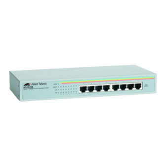
Chapter 1 Product Description Overview This chapter describes the features of the following unmanaged Fast Ethernet switches: AT-FS708 AT-FS708E Each switch model is described in Table 1: Table 1 Switch Models and Port Description Model Description AT-FS708 Eight auto-negotiating 10/100 Mbps twisted pair RJ45 ports... -
Page 18: Common Major Features
Internal power supply (100-120/200-240VAC) for AT-FS708, or external power adapter for AT-FS708E Desktop or rackmounting (rackmount option for AT-FS708 only) The switch models described in this guide complement the other Allied Telesyn Fast Ethernet products, providing simple, cost-effective solutions for switching between 10 and 100 Mbps. -
Page 19: Physical Description
AT-FS708 and AT-FS708E Switches Installation Guide Physical Description The physical description for the switches includes: Connectors Media-Dependent Interface (MDI), Port 8 LEDs Power supply Connectors Table 2 lists and defines the type of connectors available and their function. Table 2 Connector Types on Switches... -
Page 20: Mdi Port
Product Description Table 3 LED Status LEDs Color Description On indicates a valid physical link on the port. LINK/ACTIVITY Green Blinking indicates data is being transmitted. Off means no link. Off means the bandwidth is 10 Mbps. 100M Green On means the bandwidth is 100 Mbps. On indicates full-duplex transmission mode. -
Page 21: Power Supply
AT-FS708 and AT-FS708E Switches Installation Guide Power Supply The AT-FS708 uses a 40W universal internal switching power supply with 100 to 120 VAC, or 200 to 240 VAC, 50/60 Hz input rating. Allied Telesyn ships power cords with the units to the U.S., Continental Europe, and the U.K. -
Page 23: Chapter 2 Installation
Installation Requirements” on page iii. Verifying Package Contents Make sure that the package includes the following items: One AT-FS708 or AT-FS708E switch One AC power cord (AT-FS708) or power adapter (AT-FS708E) Two rackmounting brackets with screws (AT-FS708 only) Four self-adhesive rubber feet Warranty card... -
Page 24: Site Requirements
Connect power: — For AT-FS708, attach one end of the power cord to the back of the switch and the other end to the power source. — For AT-FS708E, plug the power adapter into the power receptacle,... -
Page 25: Rackmount Installation
Attach the data cables and observe normal operation as indicated by the port LEDs. Use only one Port 8, either Port 8 MDI or Port 8 MDI-X. Rackmount Installation Rackmount installation applies to the AT-FS708 only. You will need a Phillips screwdriver for this installation. Caution Do not use power tools to perform this installation. -
Page 26: Configuration
Figure 4 shows the switch connected to end stations and a server. The basic physical connection for this configuration requires connecting one of the switch’s ports to the adapter card of an end station. Cat 5, UTP wiring Figure 4 AT-FS708 Connected to End Stations... -
Page 27: Cascade Configuration
Uplink Configuration For 100 Mbps connection to the backbone, use Port 8 MDI. Figure 6 illustrates how the AT-FS708 switches can be used as an uplink to the backbone in a typical office complex using Category 5 UTP cable. - Page 28 Installation CORPORATE BACKBONE AT-FS708 Switch Sales AT-FS708 Switch Engineering AT-FS708 Switch Finance FORMULA 8200 Switch SNMP Station Figure 6 Switches as Uplink to the Backbone...
-
Page 29: Chapter 3 Troubleshooting
Chapter 3 Troubleshooting This chapter describes the procedures to test and troubleshoot the switches. Connectivity Testing In the following procedure, you will test each port for a valid connection and to confirm the correct operation of the network. Start with Ports 1 and 2. Connect these two ports of a single switch to two nodes or workstations and turn on the switch power. -
Page 30: Problem Solving
Troubleshooting Problem Solving Is the unit receiving power? Check the Power LED on the front of the switch. This green LED should be lit. Note The switch performs a self-diagnostic test upon power on, and takes about 20 seconds to complete. If the Power LED is not on, check both ends of the power cord or adapter. - Page 31 AT-FS708 and AT-FS708E Switches Installation Guide Problem 4: There is data loss between the switch and one of the connected network nodes. Solution 4: — Make sure that the distance between the switch and the connected network device is no greater than 100 m (328 ft).
-
Page 33: Appendix A Switch Specifications
Appendix A Switch Specifications Physical Characteristics Chassis Dimensions: AT-FS708 9.81 in (W) x 4.5 in (D) x 1.5 in (H) 249 mm (W) x 114 mm (D) x 38 mm (H) AT-FS708E 7.75 in (W) x 4.56 in (D) x 1.44 in (H) -
Page 34: Cabling Specifications
STP/UTP Category 5 wiring, 100 ohm impedance 100 m (328 ft) between switch and network node. Electrical Specifications AT-FS708 Internal Power: Internal universal power supply with 100 to 240 VAC, 50/60 Hz, 0.3 A input. AT-FS708E External Power: External power adaper provides 13-19 UDC, 800 mA maximum. -
Page 35: Network Specifications
AT-FS708 and AT-FS708E Switches Installation Guide Network Specifications Table 5 provides an overview of IEEE 802.3 and 802.3u specifications for 10Base-T and 100Base-TX network configurations using shielded twisted-pair wiring. Table 5 IEEE 802.3 and 802.3u Network Specifications 10Base-T 100Base-TX Media... -
Page 36: 100Base-Tx Connector Pinouts
Switch Specifications 100Base-TX Connector Pinouts Straight-through Cable 1 TX+ TX+ 1 2 TX- TX- 2 3 RX+ RX+ 3 6 RX- RX- 6 Crossover Cable 1 TX+ TX+ 1 2 TX- TX- 2 3 RX+ RX+ 3 6 RX- RX- 6... -
Page 37: Appendix B
Appendix B Technical Support Fax Order Name _________________________________________________________________________ Company______________________________________________________________________ Address_______________________________________________________________________ City ___________________________State/Province___________________________________ Zip/Postal Code ______________________ Country___________________________________ Phone __________________________________ Fax___________________________________ Incident Summary Model number of Allied Telesyn product I am using ___________________________________ Network software products I am using _____________________________________________ _______________________________________________________________________ Brief summary of problem _______________________________________________________ _______________________________________________________________________ Conditions (List the steps that led up to the problem.) ________________________________ _______________________________________________________________________... -
Page 39: At-Fs708 And At-Fs708E Switches Installation Feedback
Appendix C AT-FS708 and AT-FS708E Switches Installation Feedback Please tell us what additional information you would like to see discussed in the guide. If there are topics you would like information on that were not covered in the guide, please photocopy this page, answer the questions and fax or mail this form back to Allied Telesyn International Corp. -
Page 41: Appendix D Where To Find Us
Appendix D Where To Find Us For Technical Support or Service Location Phone Americas 1 (800) 428-4835 1 (918) 628-3222 United States, Canada, Mexico, Central America, South America Asia (+65) 3815-613 (+65) 3833-830 Singapore, Taiwan, Thailand, Malaysia, Indonesia, Korea, Philippines, China, India Australia (+61) 2-943-5111 (+61) 2-9438-4966...
Need help?
Do you have a question about the AT-FS708 and is the answer not in the manual?
Questions and answers