Table of Contents
Advertisement
Advertisement
Table of Contents

Related Manuals for Allied Telesis AT-FS750


Summary of Contents for Allied Telesis AT-FS750
- Page 1 AT-FS750/24-41 L2 Managed Switch Web GUI Manual RevA...
-
Page 2: Table Of Contents
Contents CHAPTER 1 PREFACE..........................1-1 ............................1-1 BOUT UIDE .............................. 1-1 ERMS SAGE ........................1-1 OPYRIGHT AND RADEMARKS CHAPTER 2 PRODUCT INTRODUCTION ....................2-1 ..........................2-1 RODUCT NTRODUCTION ............................... 2-1 RONT ANEL ..............................2-2 ANEL CHAPTER 3 HARDWARE INSTALLATION ....................3-1 CHAPTER 4 USING THE WEB USER INTERFACE ................. - Page 3 MSTP ................................6-6 MSTP Global Configuration ............................ 6-8 MSTP Timers Configuration ............................ 6-9 CIST Settings ................................6-9 MSTP VLAN Mapping ............................6-10 MSTP Port Settings ..............................6-11 MSTP CIST Port Status ............................6-12 RSTP ................................. 6-12 RSTP Global Configuration ........................... 6-12 RSTP Configuration ...............................
- Page 4 RMON E ........................9-7 VENTS ONFIGURATION CHAPTER 10 SWITCH STATISTICS ..................... 10-9 ..........................10-9 WITCH TATISTICS ..........................10-9 NTERFACE TATISTICS ..........................10-10 THERNET TATISTICS VLAN S ............................. 10-10 TATISTICS MSTP ..............................10-11 MSTP Information ............................... 10-11 MSTP CIST Port Statistics ........................... 10-11 MSTP MSTI Port Statistics ..........................
-
Page 5: Chapter 1 Preface
Reproduction in any manner whatsoever without the written permission of Allied Telesis Inc. is strictly forbidden. Trademarks used in this text: Allied Telesis and the Allied Telesis logo are trademarks of Allied Telesis Inc.; Microsoft and Windows are registered trademarks of Microsoft Corporation. -
Page 6: Chapter 2 Product Introduction
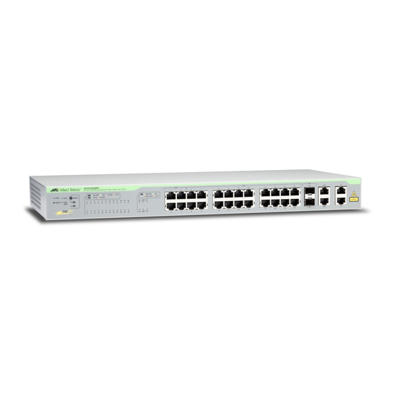
AT-FS750/24-41 Web User Interface Manual Chapter 2 Product Introduction Product Introduction AT-FS750/24-41 is a L2 managed switch with 24-Port 10/100Mpbs ports , 2 10/100/1000Mbps ports and 2 Combo 10/100/1000Mbps/SFP ports. See below for the introduction of switch outlook. Front Panel Console Port Providing a out-of-band connection to the Switch for management traffic. -
Page 7: Rear Panel
AT-FS750/24-41 Web User Interface Manual Rear Panel Power Connector The power port is where to connect the AC power cord. -
Page 8: Chapter 3 Hardware Installation
AT-FS750/24-41 Web User Interface Manual Chapter 3 Hardware Installation This chapter provides unpacking and installation information for AT-FS750/24-41 Unpacking Open the shipping carton and carefully unpack its contents. Please consult the packing list located in the User Manual to make sure all items are present and undamaged. - Page 9 AT-FS750/24-41 Web User Interface Manual Figure 3 – Mount the Switch in the rack or chassis Safety Instructions Caution A) Elevated Operating Ambient - If installed in a closed or multi-unit rack assembly, the operating ambient temperature of the rack environment may be greater than room ambient.
-
Page 10: Using The Web User Interface
AT-FS750/24-41 Web User Interface Manual Chapter 4 Using the Web User Interface After a successful physical installation, you can configure the Switch, monitor the network status, and display statistics using a web browser. Supported The embedded Web-based Management currently supports the following web... - Page 11 AT-FS750/24-41 Web User Interface Manual Figure 7 – Enter the IP address 10.90.90.90 in the web browser The default user name and password are: Note User Name Password Priviledge root password guset guest123 After login successfully, following page will appear.
- Page 12 AT-FS750/24-41 Web User Interface Manual function tree. To terminate the web management session, click Log Out in the up-left coner. Function Tree...
-
Page 13: Configuring System Basic Functions
AT-FS750/24-41 Web User Interface Manual Chapter 5 Configuring System Basic Functions System Basic Function List System Information User Account Management VLAN Management IP Settings IP Authorized Manager SNMP SNMP User/Group Table Configuration SNMP Group Access Table Configuration... -
Page 14: User Account
AT-FS750/24-41 Web User Interface Manual Hardware Version The hardware version of this device. Firmware Version The firmware verision of the device. Device Name The name of the device. Default is SysName. Device Contact The dentification information of a contact person. Deafult is SysContact. -
Page 15: Management Ip Settings
AT-FS750/24-41 Web User Interface Manual Figure 11 – System > Management VLAN Parameter Description Management VLAN The VLAN ID of management VLAN. It can be a single VLAN ID from 1 to 4094, a range of VLAN IDs separated by a hyphen (-) ,or a series of non-continuous numbers divided by a comma (,) Click ADD to submit the changes and the Remove button will remove an existed VLAN ID. -
Page 16: Snmp
AT-FS750/24-41 Web User Interface Manual Parameter Description IP Address IP address of authorized manager Subnet Mask Subnet mask of the authorized IP address Port List (Incoming) Interface of the authorized administrator is allowed to connect to VLANs Allowed VLAN ID of the authorized administrator is allowed to connect to. It can be a... -
Page 17: Snmp View Table Configuration
AT-FS750/24-41 Web User Interface Manual Figure 15 – System > SNMP > Group Access Table Parameter Description Group Name SNMP group name Read View Name The name of group (view) has read privilege and is allowed to access the specified MIB object groups. -
Page 18: Snmp Community Settings
AT-FS750/24-41 Web User Interface Manual Figure 16 – System > SNMP > View Table Parameter Description View Name SNMP view name Subtree OID The object ID of MIB tree OID Mask The mask of OID included – Includes the object in the list that the SNMP administrator can View Type access. -
Page 19: Snmp Engine Id Configuration
AT-FS750/24-41 Web User Interface Manual Figure 18 – System > SNMP > Trap Manager Parameter Description Host IP Address The IP address of a host that can access to the device by SNMP. SNMP version Specify the SNMP version to be used, which can be v1, v2c, or v3. -
Page 20: Ssl Configuration
AT-FS750/24-41 Web User Interface Manual Version Specify the SSH version supported. V2 – SSH v2 is supported. This is the default value. V1 & V2 – Both SSH v1 and V2 are supported. Cipher To specify SSH Cipher algorithm. 3DES-CBC - 3DES (Triple_Data Encryption Standard) encryption algorithm in CBC (Cipher Blocking Chain). -
Page 21: Sntp
AT-FS750/24-41 Web User Interface Manual Figure 22 – System > System Log Parameter Description Syslog Status The status of syslog server function. Default is enabled. Time Stamp Specifies if time stamp is attached with syslog messages. Default is enabled. Messages Buffered The size of internal logging buffer. -
Page 22: Sntp Daylight Saving Time
AT-FS750/24-41 Web User Interface Manual is disabled. SNTP Poll Interval in To set the time interval that SNTP synchronizes the time on SNTP server, and Seconds (30-86400) the range is from 30 to 86400 seconds. Default is 30. SNTP Primary Server To set the primary SNTP server IP address. -
Page 23: Restore Configuration
AT-FS750/24-41 Web User Interface Manual Figure 25 – System > Configuration > Save Parameter Description Save option Options to save the running configuration: Flash Save: Save to flash drive with designated file name. Remote Save: Save to the remote tftp server with designated IP address and file name. -
Page 24: Reboot
AT-FS750/24-41 Web User Interface Manual Click Apply to submit the changes and the Reset button will clear the information inputed. Reboot This page is to rebooth the system. Figure 28 – System > Reboot Click Reboot to warm start the device. -
Page 25: Configuring Layer 2 Management Functions
AT-FS750/24-41 Web User Interface Manual Chapter 6 Configuring Layer 2 Management Functions Layer 2 Management Function List Port Manager Port Basic Settings Port Monitoring Port Control VLAN VLAN Basic Information VLAN Port Settings Static VLAN Configuration Dynamic VLAN... -
Page 26: Port Manager
AT-FS750/24-41 Web User Interface Manual Port Manager Port Basic Settings This page is to configure basic settings of switch ports. Figure 29 – Layer2 Management > Port Manager > Basic Settings Parameter Description Port Specify the switch port to be configured. -
Page 27: Port Control
AT-FS750/24-41 Web User Interface Manual Figure 30 – Layer2 Management > Port Manager > Port Monitoring Parameter Description Status To enable/disable the port monitoring session on the device. Default is disabled. Monitoring Port Specify the source port of the mirror session. -
Page 28: Vlan
AT-FS750/24-41 Web User Interface Manual Figure 31 – Layer2 Management > Port Manager > Port Control Parameter Description Port Specify the switch port to be configured. Mode To enable/diable auto-negotiation function on ports. Default is Auto. Duplex To set the port duplex mode. Possible values are: Full: Port runs at full duplex mode. -
Page 29: Vlan Port Settings
AT-FS750/24-41 Web User Interface Manual Figure 32 – Layer2 Management > VLAN > Basic Information Parameter Description VLAN Mode Choose from 802.1Q VLAN or Asymmetric VLAN modes. Default is 802.1Q VLAN. Maximum VLAN ID Display the maximum VLAN ID can be configured. Default is 4095. -
Page 30: Static Vlan Configuration
AT-FS750/24-41 Web User Interface Manual Default is All. Ingress Filtering To enable/disable the filter of ingress packets not with the same VLAN tag as the VLAN membership of the port. Default is Enabled. Click Apply to submit the changes. Static VLAN Configuration This page is to set up the static VLAN configuration. -
Page 31: Dynamic Vlan Port Configuration
AT-FS750/24-41 Web User Interface Manual Parameter Description Garp System Control Choose Start to enable GARP function, and Shutdown to disable it. It is needed for using dynamic VLAN function. Defualt is Start. Dynamic VLAN Status To set the status of dynamic VLAN function from Enabled or Disabled. -
Page 32: Mstp
AT-FS750/24-41 Web User Interface Manual Figure 37 – Layer2 Management > Dynamic VLAN > Port Settings Parameter Description Port No Specify the switch port to be configured. GarpJoinTime Specify the join time of GARP. Deafult is 20 milli-seconds. 2^30-14)(msecs) GarpLeaveTime (30 ~ Specify the leave time of GARP. -
Page 33: Mstp Timers Configuration
AT-FS750/24-41 Web User Interface Manual Parameter Description System Control To activate or shutdown the MSTP function. Select Start to activate the MSTP function, Shutdown to shutdown MSTP function. MSTP Status To enable or disable the MSTP. Select Enabled to enable the MSTP function, Disabled to disable the MSTP function. -
Page 34: Mstp Vlan Mapping
AT-FS750/24-41 Web User Interface Manual Figure 40 – Layer2 Management > MSTP > Port Configuration Parameter Description Select Select a port to apply the configuration changes. Port Port ID. Path Cost Specify the path cost of the port. Possible value is 0-200000000. Default... -
Page 35: Mstp Port Settings
AT-FS750/24-41 Web User Interface Manual Figure 41 – Layer2 Management > MSTP > VLAN Mapping Parameter Description MSTP Instance ID Specify which MST instance to be mapped. Add VLAN Add a VLAN to the map list of this MST instance. -
Page 36: Mstp Cist Port Status
AT-FS750/24-41 Web User Interface Manual Port State Specify the current state of this port. Priority Specify the spannping tree port priority. Possible value is 0-240. Default is 128. Cost Specify the path cost of the port. Possible value is 0-200000000. Default... -
Page 37: Rstp Configuration
AT-FS750/24-41 Web User Interface Manual 1. MSTP function must be shutdown before activate RSTP. Note 2. RSTP status must be enabled before configure other RSTP details. RSTP Configuration This page is to configure the timers and other details of RSTP functions. -
Page 38: Rstp Port Status
AT-FS750/24-41 Web User Interface Manual Figure 46 – Layer2 Management > RSTP > Port Stettings Parameter Description Select Select a port to apply the changes. Port Port ID. Port Role Specify the current role of the port. Port Priority Specify the spannping tree port priority. Possible value is 0-240. Default is 128. -
Page 39: La Basic Settings
AT-FS750/24-41 Web User Interface Manual Figure 47 – Layer2 Management > RSTP > Port Status Click 1-12, 13-24, 25-28 to display the statistics for corresponding ports. LA Basic Settings This page is to configure the link aggregation basic settings. Figure 48 – Layer2 Management > LA > Basic Settings... -
Page 40: La Port Channel Settings
AT-FS750/24-41 Web User Interface Manual Figure 49 – Layer2 Management > LA > Interface Settings Parameter Description Port Channel ID Specify the ID of port channel that will apply the changes. Adlin Status To activate or shutdown a port channel interface. Select Up to activate it, Down to shutdown it. -
Page 41: La Port Settings
AT-FS750/24-41 Web User Interface Manual LA Port Settings This page is to configure port related link aggregation settings. Figure 51 – Layer2 Management > LA > Port Settings Parameter Description Select Select a port to submit the changes. Port Port ID. -
Page 42: La Load Balancing Policy
AT-FS750/24-41 Web User Interface Manual Figure 52 – Layer2 Management > LA > Port State Infor LA Load Balancing Policy Figure 53 – Layer2 Management > LA > Load Balancing Parameter Description Select Select a port channel to apply the configuration change. - Page 43 AT-FS750/24-41 Web User Interface Manual server; Local will use the local database. Default is Local. Network Access Specify the remote RADIUS server authenticator ID. Server ID Protocol Version Specify the protocol version of 802.1X. Click Apply to submit the changes.
- Page 44 AT-FS750/24-41 Web User Interface Manual Click Apply to submit the changes. Click 1-12, 13-24, 25-28 to configure 802.1X port settings for corresponding ports. 802.1X Timer Configuration This page is to configure the 802.1X timers of the device. Figure 56 – Layer2 Management > 802.1X > Timers...
-
Page 45: Radius Server Configuration
AT-FS750/24-41 Web User Interface Manual Figure 57 – Layer2 Management > 802.1X > Local AS Parameter Description User Name Specify the user name of the new user entry. Password Specify the password of the new user entry. Permission Specify if the new user is allowed to access the network. -
Page 46: Igmp Snooping
AT-FS750/24-41 Web User Interface Manual Server ID Specify the new RADIUS server ID. The possible ID is 1-10. IP Address Specify the IP address of the new RADIUS server. Shared Secret Specify the encryption key between RADIUS server and clients. -
Page 47: Igmp Snooping Timer Configuration
AT-FS750/24-41 Web User Interface Manual Parameter Description Select Select a line to change the configuration. IGMP Snooping Status To enable or disable IGMP Snooping globally. Default is enabled. Operational Status Specify the operational status of IGMP snooping function. Snooping Mode Speficy the Snooping mode of IGMP snooping function. -
Page 48: Igmp Snooping Vlan Router Ports
AT-FS750/24-41 Web User Interface Manual Figure 61 – Layer2 Management > IGMP Snooping > Interface Configuration Parameter Description VLAN ID Specify which VLAN to add to the IGMP snooping interface list below. IGMP Snooping Status Enable or disable the IGMP Snooping on this VLAN. -
Page 49: Static Mac Entries
AT-FS750/24-41 Web User Interface Manual Figure 63 – Layer2 Management > IGMP Snooping > Group Imformation Static MAC Entries Static MAC Address Configuration This page is to create or configure static unicast MAC address in the L2 forwarding database. Figure 64 – Layer2 Management > Static MAC Entries > Unicast Entries... -
Page 50: Port Security Settings
AT-FS750/24-41 Web User Interface Manual Figure 65 – Layer2 Management > Static MAC Entries > Multicast Entries Parameter Description VLAN ID Specify the VLAN ID of the new MAC address entry. MAC Address Specify the MAC address if this new entry. - Page 51 AT-FS750/24-41 Web User Interface Manual Figure 66 – Layer2 Management > Static MAC Entries > Port Security Settings Parameter Description Select Select a port to apply the configuration changes. Port Port ID. Admin State To enable or disable the port security function. Default is disable.
-
Page 52: Chapter 7 Configuring Acl Functions
AT-FS750/24-41 Web User Interface Manual Chapter 7 Configuring ACL Functions ACL Function List MAC ACL Configuration IP Standard ACL Configuration IP Extended ACL Configuration Classmap Settings Policymap Settings MAC ACL Configuration This page is to create/configure a rule to MAC Access Control List. -
Page 53: Ip Standard Acl Configuration
AT-FS750/24-41 Web User Interface Manual 0x6004(24580). lavc-sca 0x6007(24583). mop-console 0x6002(24578). mop-dump 0x6001(24577). msdos 0x8041(32833). mumps 0x6009(24585). netbios 0x8040(32832). vines-echo 0x0BAF(2991). vines-ip 0x0BAD(2989). xns-id 0x0807(2055). others Insert a custom Ether type (0-65535) to the right column. Click Add to create a new ACL rule, Reset to clear the value just inputed. -
Page 54: Ip Extended Acl Configuration
AT-FS750/24-41 Web User Interface Manual Figure 68 – ACL > IP Standard ACL Parameter Description ACL Number Specify the ACL ID of this rule. The possible ID of IP Standard ACL is 1-1000. Action Specify the action for packet matched. Select Permit to process the packets, Deny to discard them. - Page 55 AT-FS750/24-41 Web User Interface Manual Figure 69 – ACL > IP Extended ACL Parameter Description ACL Number Specify the ACL ID of this rule. The possible ID of IP Standard ACL is 1001-65535. Action Specify the action for packet matched. Select Permit to process the packets, Deny to discard them.
-
Page 56: Classmap Settings
AT-FS750/24-41 Web User Interface Manual Destination Port Mask Matching packet with a range of destination port. For example source port 23 with mask FFFE means 22~23. The mask options are: 8000, C000, E000, F000, F800, FC00, FE00, FF00, FF80, FFC0, FFE0, FFF0, FFF8, FFFC, FFFE, FFFF. -
Page 57: Policymap Settings
AT-FS750/24-41 Web User Interface Manual Figure 70 – ACL > Classmap Parameter Description Classmap ID Specify the classmap ID. The possible value is 1-65535. ACL ID Specify the ACL rule ID to bind. ACL Type Specify the type of the ACL rule. - Page 58 AT-FS750/24-41 Web User Interface Manual Policed-DSCP - Assign a new DSCP value to the packets. Policed-Priority - Assign a new 802.1p priority to the packets. In-Profile Action Value Specify the new value of above. When rewritng DSCP tag, the possible value is 0-63;...
-
Page 59: Chapter 8 Configuring Qos Functions
AT-FS750/24-41 Web User Interface Manual Chapter 8 Configuring QoS Functions QoS Function List Rate Limiting Storm Control Settings 802.1p Queue Mapping 802.1p Port Priority DSCP Queue Mapping Egress Queue Scheduling Settings Rate Limiting This page is to configure the rate limiting function on each port. -
Page 60: Storm Control Settings
AT-FS750/24-41 Web User Interface Manual Click Apply to submit the changes. Click 1-12, 13-24, 25-28 to configure rate limiting for corresponding ports. Storm Control Settings This page is to configure the storm control function of the device. Figure 73 – QoS > Storm Glocal Settings... -
Page 61: P Port Priority
AT-FS750/24-41 Web User Interface Manual 802.1p Port Priority This page is to configure the 802.1p priority for untagged packets receive from each port. Figure 75 – QoS > Port Priority Parameter Description Select Select a port to submit the configuration changes. -
Page 62: Egress Queue Scheduling Settings
AT-FS750/24-41 Web User Interface Manual DSCP Mapping To enable the DSCP queue mapping. When disabled, Switch will map queue with 802.1p priority. Click Apply to submit the changes. Parameter Description Type00~63 Specify which switch queue to map. The options are Class-0, Class-1, Class-2 and Class-3. -
Page 63: Chapter 9 Configuring Rmon Functions
AT-FS750/24-41 Web User Interface Manual Chapter 9 Configuring RMON Functions RMON Function List RMON Basic Settings RMON Statistics Configuration RMON History Configuration RMON Alarms Configuration RMON Events Configuration RMON Basic Settings This page is to enable or disable RMON function Figure 78 –... -
Page 64: Rmon History Configuration
AT-FS750/24-41 Web User Interface Manual Port Specify which port to enable the RMON statistics collection. Owner Specify the owner of the statistics entry. Click Add to create a new statistics entry, Reset to clear the value just inputed. Parameter Description... -
Page 65: Rmon Alarms Configuration
AT-FS750/24-41 Web User Interface Manual Port The port of the RMON history collection. Buckets Requested Specify the maximum number of RMON history collection. Buckets Granted The number of bucket granted for collecting the RMON history. Interval Specify the time interval for the history collection. -
Page 66: Rmon Events Configuration
AT-FS750/24-41 Web User Interface Manual Parameter Description Select Select a RMON alarm entry to apply the configuration changes. Index Specify the index of the RMON alarm. Interval The time interval in seconds that alarm monitors the MIB variable. Variable The MIB OID of this alarm entry. -
Page 67: Chapter 10 Switch Statistics
AT-FS750/24-41 Web User Interface Manual Description Specify the description of the event. Type Specify the action type of the event. The options are: Log - Generating syslog when event is triggered. SNMP Trap - Generating a trap message when event is triggered. -
Page 68: Ethernet Statistics
AT-FS750/24-41 Web User Interface Manual Figure 83 – Statistics > Interface Click 1-12, 13-24, 25-28 to display the Ethernet related statistics of corresponding ports. Ethernet Statistics This page is to display the Ethernet related statistics of each port. Figure 84 – Statistics > Ethernet Click 1-12, 13-24, 25-28 to display the Ethernet related statistics of corresponding ports. -
Page 69: Mstp
AT-FS750/24-41 Web User Interface Manual MSTP MSTP Information This page is to display current MSTP settings and states of the Switch. Figure 86 – Statistics > MSTP > MSTP Information MSTP CIST Port Statistics This page is to display the MSTP traffic statistics of ports. -
Page 70: Rstp Port Statistics
AT-FS750/24-41 Web User Interface Manual Figure 89 – Statistics > RSTP > RSTP Information RSTP Port Statistics This page is to display the RSTP traffic statistics of ports. Figure 90 – Statistics > RSTP > Port Statistics Parameter Description Update – To display the latest statistics information. -
Page 71: La Neighbour Statistics Information
AT-FS750/24-41 Web User Interface Manual Click 1-12, 13-24, 25-28 to display the Link Aggregation neighbours information of corresponding ports. LA Neighbour Statistics Information This page is to disply the information of Link Aggregation neibubours. Figure 92 – Statistics > LA > Neighbour Stats Click 1-12, 13-24, 25-28 to display the Link Aggregation neighbours information of corresponding ports. -
Page 72: Radius Server Statistics
AT-FS750/24-41 Web User Interface Manual RADIUS Server Statistics This page is to display the traffic statistics to RADIUS server. Figure 94 – Statistics > 802.1X > Radius IGMP Snooping IGMP Snooping Clear Statistics This page is to reset the IGMP Snooping traffic counters. -
Page 73: Icmp Statistics
AT-FS750/24-41 Web User Interface Manual Figure 97 – Statistics > IP > ARP Cache ICMP Statistics This page is to display the ICMP traffic statistics of the Switch. Figure 98 – Statistics > IP > ICMP Statistics RMON This page is to display the RMON Statistics of the Switch. -
Page 74: Snmp
AT-FS750/24-41 Web User Interface Manual Figure 100 – Statistics > MAC Address Table Parameter Description VLAN ID Display the MAC addresses under a given VLAN. MAC Address Display a specific MAC address in FDB. Port Display the MAC addresses learned under a given port.
Need help?
Do you have a question about the AT-FS750 and is the answer not in the manual?
Questions and answers