Table of Contents
Advertisement
Quick Links
Copyright
All rights are reserved. No part of this publication may be reproduced, transmitted, transcribed,
stored in a retrieval system or translated into any language or computer language, in any form or by
any means, electronic, mechanical, magnetic, optical, chemical, manual or otherwise, without the
prior written permission of the company. Brands and product names are trademarks or registered
trademarks of their respective companies.
The vendor makes no representations or warranties with respect to the contents herein and especially
disclaim any implied warranties of merchantability or fitness for any purpose. Further the vendor
reserves the right to revise this publication and to make changes to the contents herein without
obligation to notify any party beforehand. Duplication of this publication, in part or in whole, is not
allowed without first obtaining the vendor's approval in writing.
Disclaimer
We make no warranty of any kind with regard to the content of this user's manual. The content is
subject to change without notice and we will not be responsible for any mistakes found in this user's
manual. All the brand and product names are trademarks of their respective companies.
FCC Compliance Statement
This equipment has been tested and found to comply with the limits of a Class B digital device,
pursuant to Part 15 of the FCC Rules. These limits are designed to provide reasonable protection
against harmful interference in a residential installation. This equipment generates, uses and can
radiate radio frequency energy and, if not installed and used in accordance with the instructions, may
cause harmful interference to radio communications. Operation of this equipment in a residential area
is likely to cause harmful interference in which case the user will be required to correct the
interference at his own expense. However, there is no guarantee that interference will not occur in a
particular installation.
PX848PV Series
120410060M1N
Advertisement
Table of Contents

Related Manuals for Albatron PX848PV Series


Summary of Contents for Albatron PX848PV Series
-
Page 1: Fcc Compliance Statement
PX848PV Series Copyright All rights are reserved. No part of this publication may be reproduced, transmitted, transcribed, stored in a retrieval system or translated into any language or computer language, in any form or by any means, electronic, mechanical, magnetic, optical, chemical, manual or otherwise, without the prior written permission of the company. - Page 2 表 PX848PV Pro_PV SPEC Difference Model PX848PV PX848PV Pro 3Com 3C910 ® Intel Pentium 4 Processor (Northwood) PX848PV(V2.0) PX848PV 3Com 3C920 Pro(V2.0) PX848PV(V2.1) ® Intel Pentium 4 Processor PX848PV 【Northwood/Prescott(FMB1.0)】 3Com 3C920 Pro(V2.1)
-
Page 3: Package Contents
Do not touch the IC chips, leads, connectors or other components. Unplug the AC power when you install or remove any device on the mainboard. Package Contents PX848PV Series mainboard IDE Cable FDC Cable USB Bracket (optional) Installation and Setup Driver CD... -
Page 4: Operating System
PX848PV Series ® Intel 82848P & ICH4 ® ® Supports Socket 478 Intel Pentium 4 Processor Enabling Hyper-Threading Technology for your computer system requires ALL of the following components CPU: An Intel ® ® Pentium 4 Processor with HT Technology Chipset: An Intel ®... -
Page 5: Table Of Contents
Contents CHAPTER 1. GETTING STARTED ............1 ......................1 NTRODUCTION ......................2 PECIFICATION ................... 5 UICK ONTENT ABLE ....................... 6 ONFIGURATION Layout of PX848PV Pro..................6 Layout of PX848PV ..................... 7 ..................8 ARDWARE NSTALLATION CPU Processor Installation ................... 8 Memory Installation ..................... 9 Back Panel Configuration................... -
Page 6: Chapter 1. Getting Started
4 (Northwood) Processors with a FSB (Front Side Bus) frequency of 800/533/400 MHz. The PX848PV Series provides 2 DIMM sockets using 184 pin DDR SDRAM with a total capacity of up to 2GB. You can install unbuffered & non-ECC DDR400/ 333/ 266 (PC3200/ 2700/ 2100) SDRAM. -
Page 7: Specification
PX848PV Series Specification CPU: ® Supports Socket 478 Pentium 4 processor (Northwood) Supports Hyper Threading Technology Speed: 400/ 533/ 800 MHz Front Side Bus frequency 33MHz, 32 bit PCI interface (PCI 2.3 compliant) 66MHz AGP 3.0 compliant interface that supports 8X/4X data transfer modes (0.8V or 1.5V) -
Page 8: Universal Serial Bus
PX848PV Series Universal Serial Bus: Supports up to six USB 2.0 ports for USB interface devices BUS Slots: 1 AGP slot (AGP3.0 Compliant) Five 32-bit PCI bus slots Flash Memory: Supports flash memory functionality Supports ESCD functionality Hardware Monitor Function:... -
Page 9: Watch Dog Timer
PX848PV Series IDE Facilities: Supports Ultra ATA 33, Ultra ATA 66, Ultra ATA 100, BMIDE and PIO modes Supports IDE interface with CD-ROM Supports high capacity hard disk drives Supports installation of up to 4 drives, with separate IDE connections for Primary and... -
Page 10: Quick Content Table
PX848PV Series Quick Content Table Function Content Location Page CPU Socket 478 DDR DIMM 1、2 DDR DIMM Sockets ATX_12V、ATX_ PWR ATX Power Connector IDE Connectors IDE1/2 FDC Connector AGP Slot PCI 1、2、3、4、5 PCI Slots CPU FAN、Chassis FAN、 CPUFAN、CHASFAN、AUXFAN Auxiliary FAN SW/LED、PWRLED... -
Page 11: Configuration
PX848PV Series Configuration Layout of PX848PV Pro KB/MS CPUFAN USB/LAN Socket 478 PRT/COM ATX_12V Intel SOUND 82848P AUXFAN Winbond W83627HF IDE2 IDE1 PCI1 PCI2 CHIP PCI3 Intel BAT1 ICH4 PCI4 BIOS CASEOPEN PCI5 PWRLED CD-IN SW/LED CHASFAN SPDIF IrDA USB3... -
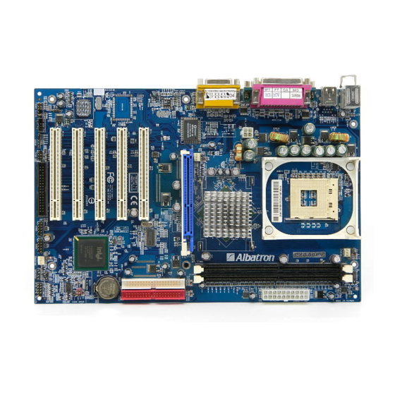
Page 12: Layout Of Px848Pv
PX848PV Series Layout of PX848PV KB/MS CPUFAN Socket 478 PRT/COM ATX_12V Intel SOUND 82848P AUXFAN Winbond W83627HF IDE2 IDE1 PCI1 PCI2 PCI3 Intel BAT1 ICH4 PCI4 BIOS CASEOPEN PCI5 PWRLED CD-IN SW/LED CHASFAN SPDIF IrDA USB3 USB2 FRONT AUDIO SPEAKER... -
Page 13: Hardware Installation
PX848PV Series Hardware Installation This section will assist you in quickly installing your system hardware. Wear a wrist ground strap before handling components. Electrostatic discharge may damage your system components. CPU Processor Installation ® ® This mainboard supports Intel Pentium 4 processors using a Socket 478. -
Page 14: Memory Installation
PX848PV Series FAN Headers Three power headers are available for cooling fans, which play an important role in maintaining the ambient temperature in your system. +12V S ocke t 4 78 Ground Sensor +12V Ground Sensor CPUFAN Intel 82848P Winbond... - Page 15 PX848PV Series The PX848PV provides two DIMM sockets which support 184-pin DDR DIMM modules with a total memory capacity of up to 2 GB. Each DIMM socket is capable of using a memory module containing up to 1 GB. RAM Module Installation: Pull the white plastic tabs on each side of the slot away from the slot.
-
Page 16: Back Panel Configuration
PX848PV Series Back Panel Configuration PS/2 Game Port Printer Port Mouse COM1 COM2 PS/2 Speaker Mic In Keyboard Line In PS/2 Mouse & PS/2 Keyboard Connectors: KB/MS This mainboard provides a standard PS/2 mouse connector and PS/2 Keyboard connector. The pin... -
Page 17: Audio Port Connectors
PX848PV Series Serial and Parallel Interface Ports The mainboard comes equipped with two back panel serial ports and one parallel port. These interface ports will be explained below. Printer Port COM1 COM2 Parallel Interface Port: PRT The parallel port on your system has a 25-pin, DB25 connector and is used to interface with parallel printers and other devices using a parallel interface. -
Page 18: Front Panel Indicator: Sw/Led、Pwrled、Speaker
PX848PV Series Front Panel Indicator: SW/LED、PWRLED、SPEAKER PWRLED PC_BEEP Ground SPEAKER Hard Driver HD LED (+) Power LED (+) Power HD LED (-) Power LED (-) Power Button (+) Reset Control (-) Reset Power-on Reset Control (+) Power Button (-) Button... -
Page 19: Connectors
PX848PV Series Connectors Floppy Disk Connector: FDC This mainboard provides a standard floppy disk connector (FDC) that supports 360K, 720K, 1.2M, 1.44M and 2.88M floppy diskettes. This connector supports the floppy drive ribbon cables provided in the packaging. Hard Disk Connectors: IDE1-2 This mainboard has a 32-bit Enhanced PCI IDE Controller that supports PIO Mode 0~4, Bus Master, Ultra ATA 33/ 66/ 100. -
Page 20: Headers & Jumpers
PX848PV Series Headers & Jumpers Case Open Warning Jumper: CASE OPEN This connector is used to notify the user when the computer case has been previously opened. To configure this functionality, your computer case must be equipped with a “ case open” cable which you need to attach to the CASE OPEN jumper. -
Page 21: Irda
PX848PV Series Infrared Header: IrDA This IrDA connector can be configured to support wireless infrared and is used to attach to an infrared sensing device. After the IrDA interface is configured, you can use this connector for connectionless data transfer to and from portable devices such as laptops and PDAs. -
Page 22: Audio Connectors
PX848PV Series Audio Connectors This mainboard provides three connectors as part of its audio Subsystem. Ground MIC_VREF Front out_R Rear out_R Front out_L Rear out_L FRONT AUDIO Left In Ground Ground Right In CD-IN SPD_OUT Ground SPD_IN SPDIF CD-ROM Audio-In Header: CD-IN This header is used to connect to a CD-ROM / DVD audio cable. -
Page 23: Slots
PX848PV Series Slots The slots in this mainboard are designed for expansion cards used to complement and enhance the functionality of the mainboard. PCI Slots AGP Slot AGP (Accelerated Graphics Port) Slot: AGP This mainboard is equipped with an Accelerated Graphics Port (AGP) (0.8V or 1.5V) to support video cards. -
Page 24: Chapter 2. Bios Setup
PX848PV Series Chapter 2. BIOS Setup Introduction This section describes PHOENIX-AWARD™ BIOS Setup program. The Setup program allows users to modify the basic system configuration. The configuration information is then saved to CMOS RAM where the data is sustained by battery after power-down. -
Page 25: Key Function
PX848PV Series Supported CPUs ® ® This PHOENIX-AWARD™ BIOS supports the Intel Pentium 4 (Northwood/ Prescott) CPUs. Key Function In general, you can use the arrow keys to highlight items, press <Enter> to select, use the <PgUp> and <PgDn> keys to change entries, press <F1> for help and press <Esc> to quit. The following table provides more detail about how to navigate within the BIOS Setup program. -
Page 26: Main Menu
PX848PV Series Main Menu When you enter the PHOENIX-AWARD™ BIOS Utility, the Main Menu will appear on the screen. The Main menu allows you to select from several configuration options. Use the left/right arrow keys to select a particular configuration screen from the top menu bar or use the down arrow key to access... - Page 27 PX848PV Series Main Menu Setup Configuration Options Item Options Description Set the system date. Note that the ‘Day’ automatically Date mm dd yyyy changes when you set the date. Time Hh: mm: ss Set the current time of the system.
-
Page 28: Advanced Bios Features
PX848PV Series Advanced BIOS Features First /Second/Third Boot Device Select the order in which devices will be searched in order to find a boot device. Options: Removable (default for first boot device)、HardDisk (default for third boot device)、 CDROM (default for second boot device)、Legacy LAN、Disabled... -
Page 29: Quick Power On Self Test
PX848PV Series Hyper-Threading Technology This option allows you to enable/disable Hyper-Threading functionality. This item only applies when the CPU installed supports Hyper-Threading Technology. Options: Disabled (default)、Enabled Quick Power On Self Test Allow the system to skip certain tests while booting. This will speed up the boot process. -
Page 30: Advanced Chipset Features
PX848PV Series HDD S.M.A.R.T. Capability Self Monitoring Analysis and Reporting Technology is a technology that enables a PC to attempt to predict the possible failure of storage drives. Options: Disabled (default)、Enabled Intel OSB Logo Show This item allows you to show or hide the Intel OSB logo. Options: Enabled (default)、Disabled... -
Page 31: Video Bios Cacheable
PX848PV Series Video BIOS Cacheable Select “Enabled” to allow caching of the video BIOS which may improve performance. If any other program writes to this memory area, a system error may result. Options: Enabled, Disabled (default) Memory Hole at 15M-16M When enabled, you can reserve an area of system memory for ISA adapter ROM. -
Page 32: Pci Slot
PX848PV Series PCI / VGA Palette Snoop Some graphic controllers that are not VGA compatible take the output from a VGA controller and map it to their display as a way to provide boot information and VGA compatibility. Options: Disabled (default)、Enabled PCI Latency Timer (CLK) This item allows you to set up the PCI Latency Time (0-255). -
Page 33: Spread Spectrum
PX848PV Series CPU Speed Setting This item displays the current CPU Speed. DDR:CPU Ratio This item allows you to adjust your “DRAM:CPU Clock Ratio” and overclock the DDR speeds of the system. The options that are available for this item will depend on the factory default setting for the “CPU Host Frequency”... - Page 34 PX848PV Series AGP/PCI/SRC Speed Setting This item determines the AGP, PCI and SRC frequencies (speed settings). You can set these frequencies using the supplied BIOS options. One of the options available to you is “Auto, Auto, Auto”. Using the “Auto, Auto, Auto” option will instruct the system to automatically calculate these frequencies based on the factory default “CPU Host Frequency”...
-
Page 35: Integrated Peripherals
PX848PV Series Integrated Peripherals Init Display First With systems that have multiple video cards, this option determines whether the primary display uses a PCI slot or an AGP slot. Options: AGP (default)、PCI Slot OnChip IDE Device IDE HDD Block Mode Block mode is otherwise known as block transfer, multiple commands, or multiple sector read/write. -
Page 36: Onboard Device
PX848PV Series IDE Primary / Secondary /Master / Slave UDMA Ultra DMA/100 functionality can be implemented if it is supported by the IDE hard drives in your system. As well, your operating environment requires a DMA driver (Windows 95 OSR2 or a third party IDE bus master driver). -
Page 37: Power On Function
PX848PV Series Onboard I/O Chip Setup PWRON After PWR-Fail This field will determine whether your system will boot after restoring power after a power failure. If you select “On”, the system will boot whether or not the system was on before power failure. If you select “Former-Sts”, the system will be restored to the status before the power failure. -
Page 38: Ir Transmission Delay
PX848PV Series IR Transmission Delay This item allows you to enable/disable IR transmission delay. This field only configurable if “UART Mode Select” is set to “ASKIR” or “IrDA”. Options: Enabled (default)、Disabled UR2 Duplex Mode Select the transmission mode used by the IR interface. Full-duplex mode permits simultaneous bi-directional transmission. - Page 39 PX848PV Series Game Port Address Game Port I/O Address. Options: 201 (default)、209、Disabled Midi Port Address Midi Port Base I/O Address. Options: 330、300 (default)、290、Disabled Midi Port IRQ This determines the IRQ that the Midi Port will use. Options: 5、10 (default)
-
Page 40: Power Management
PX848PV Series Power Management The Power Management Setup Menu allows you to configure your system to utilize energy conservation features as well as power-up/ power-down options. ACPI Suspend Type The item allows you to select the suspend type using the ACPI operating system. -
Page 41: Video Off Method
PX848PV Series 2. Max. Power Saving Maximum power management (only available for sl CPUs). Suspend Mode = 1 min. HDD Power Down = 1 min. 3. User Defined (default) Allows you to set each mode individually. When this option is enabled, each of the ranges are from 1 min. to 1 hr. except for HDD Power Down, which ranges from 1 min. -
Page 42: Hdd Power Down
PX848PV Series HDD Power Down When enabled, the hard disk drive will power down after a certain configurable period of system inactivity. All other devices remain active. Options: Disabled (default)、1 Min、2 Min、3 Min、4 Min、5 Min、6 Min、7 Min、8 Min、9 Min、 10 Min、11 Min、12 Min、13 Min、14 Min、15Min... -
Page 43: Hardware Monitor
PX848PV Series Time (hh: mm: ss) Alarm You can choose the hour, minute and second the system will boot up. This field is only configurable when “RTC Wake Up” is set to “Enabled”. Reload Global Timer Events When a system goes into suspend mode, certain devices must be inactive for a period of time. -
Page 44: Load Defaults
PX848PV Series Load Defaults Load System Default Settings Load System Default Settings. Load System turbo Settings Load System Turbo Settings. Load CMOS From BIOS Load defaults from flash ROM for systems without batteries. Save CMOS To BIOS Save defaults to flash ROM for systems without batteries. -
Page 45: Exit Menu
PX848PV Series Exit Menu Save & Exit Setup Save all configuration changes to CMOS (memory) and exit setup. A confirmation message will be displayed before proceeding. Exit Without Saving Abandon all changes made during the current session and exit setup. A confirmation message will be... -
Page 46: Chapter 3: Software Setup
PX848PV Series Chapter 3: Software Setup Software List Category Platform Intel Chipset INF Windows 9X/ ME/ 2000/ XP Intel IAA tool Windows 9X/ ME/ 2000/ XP 3Com LAN Driver Windows 9X/ ME/ 2000/ XP Realtek Audio Driver Windows 9X/ ME/ 2000/ XP USB 2.0 Driver... - Page 47 PX848PV Series 2. On the next screen, click the drivers that you want to install. 3. If you click the “USB2.0 Driver” from the screen in step 2, it will display the screen as left. 4. Back to the main screen, click the “Tools” button, you can choose the software to install.
-
Page 48: Chapter 4: Troubleshooting
PX848PV Series Chapter 4: Troubleshooting Problem 1: No power to the system. Power light does not illuminate. Fan inside power supply does not turn on. Indicator lights on keyboard are not lit. Causes: 1. Power cable is unplugged. 2. Defective power cable. - Page 49 PX848PV Series Problem 4: System only boots from the CD-ROM. The hard disk can be read and applications can be used but booting from the hard disk is impossible. Causes: Hard Disk boot sector has been corrupted. Solutions: Back up data and applications files. Reformat the hard drive. Re-install applications and data using backup disks.
- Page 50 PX848PV Series Problem 10: Keyboard failure. Causes: Keyboard is disconnected. Solutions: Reconnect keyboard. Replace keyboard if you continue to experience problems. Problem 11: No color on screen. Causes: 1. Faulty Monitor. 2. CMOS incorrectly set up. Solutions: 1. If possible, connect monitor to another system. If no color appears, replace monitor.
-
Page 51: Appendix I: Super 5.1 Channel Setup
PX848PV Series Appendix I: Super 5.1 Channel Setup 1. After into the system, click the audio icon from the Windows screen. 2. Click Speaker Configuration button, you can see the screen like the picture below. 3. You can choice 2, 4 or 6 channels by your speakers.
Need help?
Do you have a question about the PX848PV Series and is the answer not in the manual?
Questions and answers