NAPCO Gemini GEM-P3200 Installation Instructions Manual
Control panel/communicator
Hide thumbs
Also See for Gemini GEM-P3200:
- Programming instructions manual (76 pages) ,
- Installation instructions manual (64 pages) ,
- Addendum (2 pages)
Table of Contents
Advertisement
Quick Links
Publicly traded on NASDAQ
Symbol: NSSC
HARDWIRE
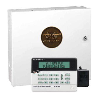
CONTROL PANEL/COMMUNICATOR
For use with "Classic" keypads (GEM-RP1CAe2, GEM-RP2ASe2, GEM-RP3DGTL and GEM-RP4RFC/GEM-RP4C)
and with "K Series" keypads (GEM-K1CA, GEM-K2AS, GEM-K3DGTL, and GEM-K4RF/GEM-K4)
G E M I N I
SYSTEM READY
01/01/06
R
1
B
4
C
7
C O M P UT E R I ZE D S E C U R I T Y S Y S T E M
"K Series" GEM-K1CA
"K Series" GEM-K3DGTL
© NAPCO 2005
R
G E M - P 3 2 0 0
12:00 AM
NEXT/YES
U
2
3
P
PRIOR/NO
Q
5
6
AREA
8
9 0
G
INSTALLATION
INSTRUCTIONS
WIRELESS
"K Series" GEM-K2AS
"K Series" GEM-K4RF/GEM-K4
WI817F 10/05
Advertisement
Table of Contents

Related Manuals for NAPCO Gemini GEM-P3200


Summary of Contents for NAPCO Gemini GEM-P3200
- Page 1 C O M P UT E R I ZE D S E C U R I T Y S Y S T E M "K Series" GEM-K2AS "K Series" GEM-K1CA "K Series" GEM-K4RF/GEM-K4 "K Series" GEM-K3DGTL © NAPCO 2005 WI817F 10/05...
-
Page 2: Changes From Previous Edition
The Access Control system (ACM), which provides integrated access control to the burglary alarm functions of the GEM-X255 control panel. • The NAPCO NetLink™ system that allows the reporting of alarms over a TCP/IP based (Intranet or Internet) net- work. •... -
Page 3: Important Note
Page 3 IMPORTANT NOTE This manual supports the keypad programming of the GEM-P3200 control panel with the NAPCO "classic" GEM- RP1CAe2, GEM-RP2ASe2, GEM-RP3DGTL and GEM-RP4RFC/GEM-RP4C keypads as well as the GEM-K1CA, GEM- K2AS, GEM-K3DGTL, and GEM-K4RF/K4 "K Series" keypads. The new "K Series" models offer the new STAY and AWAY buttons with simplified functionality, along with the new MENU and ENTER buttons. -
Page 4: Table Of Contents
TRAINING, EXPERIENCE AND INSTALLATION EQUIPMENT. IT IS RECOMMENDED THAT AFTER PROGRAMMING, THE ERROR CHECK UTILITY OF THE PCD3000 (OR PCD-WINDOWS) DOWNLOADER SOFTWARE BE USED TO VERIFY THAT THE CONTROL PANEL PRO- GRAM CONTAINS NO ERRORS OR CONFLICTS WHICH MAY INHIBIT ITS INTENDED OPERATION. NAPCO Security Systems GEM-P3200 Installation Instructions... -
Page 5: Introduction
Conventional LEDs and a sounder are also provided for annunciation. Data may be quickly and easily downloaded to the control panel using a PC-compatible computer with NAPCO's PCD- Windows Quickloader software and a PCI2000 computer interface. Or, the panel may be programmed using the keypad in its secondary mode of operation. -
Page 6: Keypad Features
Integral 4-zone EZM included in each keypad (GEM-RP1CAe2/GEM-K1CA only). Communicator Test to Central facilitates testing; Locate, Fault-Find and EZM-Locate diagnostics simplify trouble- shooting. PGM output. The NAPCO NetLink™ system allows the reporting of alarms over a TCP/IP based (Intranet or Internet) network NAPCO Security Systems GEM-P3200 Installation Instructions... -
Page 7: Specifications
GEM-RP2ASe2/GEM-K2AS: LCD Burg & Residential Fire Keypad with remote panic. GEM-RP3DGTL/GEM-K3DGTL: Digital Burg and Residential Fire Keypad with remote panic. GEM-RP4RFC/GEM-K4RF: Digital Icon Burg and Residential Fire Keypad with Integral RF Receiver. GEM-RP4C/GEM-K4: Digital Icon Burg and Residential Fire Keypad. NAPCO Security Systems GEM-P3200 Installation Instructions... - Page 8 OI249: User Guide, GEM-RP3DGTL NAPCO GROUP EUROPE LTD. OI278: User Guide, GEM-RP4C & RP4RFC Libra Wireless Transmitters and Receivers for connection to Napco In- WI1212: Installation Manual, GEM-RP4C truder Control Panels (Operates on 433MHz, European Approved Fre- WI1128: Installation Manual, GEM-RP4RFC...
-
Page 9: Summary Of Ul Requirements
Do not program any zones for “Keyswitch Arming” System must be serviced at least once every year Residential Fire and Combination Residential Fire & Burglary must program “Residential Fire” Keypad Expansion (EZM) Zones are not to be used as fire zones NAPCO Security Systems GEM-P3200 Installation Instructions... -
Page 10: Installation
24-Hour Zone or Day Zone. When used on a normally-open zone, normally-closed tamper switches (open when set) should be wired in parallel. On a normally-closed zone, install Napco TPS-2 normally-open tamper switches (closed when set) in series. -
Page 11: Wiring
Note: NFPA 74 (Household Fire Warning Equipment) requires that a fire alarm audible device be installed indoors. The User Program Code is not to be given to anyone except the authority responsible for all partitions. NAPCO Security Systems GEM-P3200 Installation Instructions... -
Page 12: Ul Commercial-Burglary Installations
In addition to Grade-B Requirements (above), one relay on the RM3008 must be programmed to trip the Ademco 7720 when the telephone line fails. Daily openings and closings are required to be transmitted by the Napco panel along with the 24-hour DACT test signal and DACT trouble conditions. -
Page 13: Testing The System
The last received signal strength for each transmission is always stored in memory and can viewed at any time using this procedure. Signal strength can also be viewed through the PCD3000 Status Screen. NAPCO Security Systems GEM-P3200 Installation Instructions... -
Page 14: Wiring Connections
P3200 Programming Instructions). Connect the device controlled by the programmable output between terminal 8 (+) and terminal 14 (-). A programming option “AuxOut Chirp on Key-fob Arm/Disarm” is available. If selected, an external siren driver can be connected to these termi- nals. NAPCO Security Systems GEM-P3200 Installation Instructions... -
Page 15: Remote Bus
Auxiliary Power provides a filtered 12 VDC nominal output which is used for powering auxiliary AUX POWER devices. NOTE: To calculate the available standby time refer to the Standby-Battery Calculation Worksheet at the back of this manual. NAPCO Security Systems GEM-P3200 Installation Instructions... -
Page 16: Reset Output
(8 additional zones per module) and GEM-RP1CAe2 Keypad (4 additional zones per keypad). Wireless zone expanders include: GEM-RECV8 (8 additional zones per receiver), GEM-RECV16 (16 additional zones per receiver) and GEM- RECV96 (88 additional zones per receiver). Wireless transmitters include: GEM-TRANS2, GEM-KEYF, GEM-SMK, GEM- PIR, GEM-DT and GEM-GB. NAPCO Security Systems GEM-P3200 Installation Instructions... -
Page 17: 4-Wire Smoke Detectors
2-wire smoke detectors as shown. If Fire Alarm Verification is desired to reset the smoke detectors, select this op- tion for the desired fire zone (zone 7 or 8).0 NOTE: Do not program Fire Alarm Verification in California NAPCO Security Systems GEM-P3200 Installation Instructions... -
Page 18: Telephone Lines
This line should not be connected to party lines or coin operated telephones. If connected to a line with call waiting, then call waiting interrupt numbers must be programmed into the CS Telephone Numbers (refer to the GEM-P3200 Programming Instructions). NAPCO Security Systems GEM-P3200 Installation Instructions... -
Page 19: Keypad Configuration Mode
A valid number will be acknowledged by a short beep; an invalid number will be rejected by a long beep. 2. Press the button to continue or press the button to exit. NAPCO Security Systems GEM-P3200 Installation Instructions... - Page 20 Keypad Configuration Mode (No Message) **Enter Now** 01 OUT OF SYSTEM (display will read “ ”). Then replace Jumper JP5 across Pins 1–2 Door Control (top two). Gate Control Light Control Control #1 Control #2 NAPCO Security Systems GEM-P3200 Installation Instructions...
- Page 21 Cut Jumper B to disable LCD backlighting. DISABLE SOUNDER Cut Jumper C to disable the sounder. (Do not disable in UL applications.) NAPCO Security Systems, Inc. 333 Bayview Avenue, Amityville, New York 11701 For Sales and Repairs, call toll free: (800) 645-9445 For direct line to Technical Service, call toll free: (800) 645-9440 Internet: http://www.napcosecurity.com...
-
Page 22: Basic Operation
Zone descriptions follow the Program Code in the normal programming sequence. Program the description, up to two lines, letter by letter. Characters are selected by pressing keypad buttons multiple times, "Cell Phone" style. Press NAPCO Security Systems GEM-P3200 Installation Instructions... -
Page 23: Arming And Disarming The System
AWAY." The RED LED will remain ON. With "K Series" keypads such as the GEM-K1CA and the GEM-K2AS, press to begin the exit delay process (the exit delay will immediately start counting down toward "000", in 10-second decrements, in- dicating the available time remaining to exit through an exit/entry door). NAPCO Security Systems GEM-P3200 Installation Instructions... -
Page 24: Arming In Stay Mode
Manager's Mode, is a low-security mode of operation. It provides quick access to other areas without having to go to another keypad of another area. To arm or disarm the alternate area (for "Classic" keypads): 1. Press representing the alternate area. 2. Press the button, then the button. NAPCO Security Systems GEM-P3200 Installation Instructions... -
Page 25: Bypassing Zones
The alarm con- ditions will then be stored in the Alarm History Log and the Total Event Log (see HISTORY LOG). NAPCO Security Systems GEM-P3200 Installation Instructions... -
Page 26: Alarm Indication
DISPLAY PHONE #'S The panel can function as an auto dialer to any of four programmed telephone numbers. (Telephone numbers must be programmed through Napco PCD-Windows Quickloader software). Select Telephone #1-4 using NEXT and PRIOR buttons, then press the button. Pick up the phone to initiate dialing of the displayed number. (The phone will appear to be discon- nected while dialing but will return to normal after a few seconds). - Page 27 Page 27 DISPLAY OP/CL NAPCO's PCD-Windows Quickloader software offers a comprehensive array of programmable opening and clos- ing suppression windows, by area, for all days of the week, for both normal and holiday schedules. A two-line dis- play of the programmed schedule may be read at the keypad. The first line indicates:...
- Page 28 2-second warning and the keypad will begin a 15-minute countdown with the sounder pulsing. Within this countdown window, arming may be delayed an additional 1 to 4 hours (using TO ARM IN 1-4HRS NAPCO Security Systems GEM-P3200 Installation Instructions...
-
Page 29: Relay Control
Press the YES button to check the status (all on or all off) of up to 2 groups programmed with any combination of up to 24 available external relays. The group number will display with a related description. Scroll through the groups using the NEXT and PRIOR buttons; change the status of the displayed group by pressing the button. NAPCO Security Systems GEM-P3200 Installation Instructions... -
Page 30: Keypad Messages
E11-NNN - KEYPAD/ACM TAMPER. Keypad or ACM cover opened. NNN is keypad number (address). E12-NN - BURG EZM TRBL. Expansion zone module failure. NN = module number. E13-NN - BURG EZM TAMPER. EZM module cover re moved. NAPCO Security Systems GEM-P3200 Installation Instructions... -
Page 31: Glossary
440Hz is received prior to dialing the access number. If the communicator must delay before dialing the access number instead of attempting to recognize the dial tone, find out how many 4-second delays must be programmed. Alarm on Day Zone See Day Zone NAPCO Security Systems GEM-P3200 Installation Instructions... - Page 32 Be sure to inform the user what their Ambush Code is, and that the Arm/Disarm Code must be entered less than 10 seconds after the Type 1 Ambush Code for an ambush report to be sent. NAPCO Security Systems GEM-P3200 Installation Instructions...
- Page 33 Output Timeout and Auto-Reset. Zones that are not programmed for Auto-Reset will not be capable of signaling another alarm until (a) the cause of the alarm has been corrected and (b) the control panel is disarmed. Also see Swinger Shutdown. Auxiliary Relay See Alarm Outputs NAPCO Security Systems GEM-P3200 Installation Instructions...
- Page 34 Lug E10 (BURG.) will go to about 1Vdc when the Burglary Output is tripped. This lug is intended for connection to UL-listed de- vices rated 5mA maximum and capable of operating over the voltage range of 8-13.0Vdc (12V, special application). Use Napco Part No.
- Page 35 3/1 with Extended Restores. Some receivers require a three-digit Account Code followed by a single-digit Alarm Code. Exam- ple. In another installation, the Alarm Subscriber Number is “123”; an alarm on Zone 1 is restored. The Restore Code for NAPCO Security Systems GEM-P3200 Installation Instructions...
- Page 36 Program Disable Auto-Reset on Day Zone to prevent repeated Day-Zone trips. This will cause the keypad display and sounder to activate only once in any arm/disarm period. If Enable Watch is selected (by area), zones programmed for Day Zone can only be activated when ACTIVATE WATCH is ac- NAPCO Security Systems GEM-P3200 Installation Instructions...
- Page 37 If the first communication is unsuccessful, the next and remaining dial attempts will remove the star button (entered as a "B" from the keypad) and the 2 subsequent digits from the Central Station telephone number. NAPCO Security Systems GEM-P3200 Installation Instructions...
- Page 38 E9 - See Fire Lug E10 - See Burglary Lug E19 - See Veri-Phone: Silence All Outputs During Audio Session E22 - Common terminal for Reset Relay. Use Napco Part No. WL1 for field wiring. Easy Arming Permits quick arming by simply pressing the button for 2 seconds.
- Page 39 (Exit-Delay Restart may be useful in reducing false alarms caused by a user who re-enters the premises shortly after exiting.) Note: In UL installations, maximum exit delay is 60 seconds; maximum entry delay is 45 seconds. In UL Mercantile installa- tions, maximum entry delay is 60 seconds. NAPCO Security Systems GEM-P3200 Installation Instructions...
- Page 40 Lug E9 (FIRE) will go to about 1Vdc when a Fire Zone programmed for Fire Output is tripped. This lug may be used for auxiliary equipment. (For use, refer to the instructions furnished with the device). Use Napco Part No. WL1 for connection.
- Page 41 The Auxiliary Relay can be programmed to activate for a programmable period of time. This allows it to be used for access func- tions such as opening and closing a garage door. This is achieved through a new KeyFob option, Access control, by programming NAPCO Security Systems GEM-P3200 Installation Instructions...
- Page 42 Typically, any zone, other then a fire zone, will automatically be unbypassed when the panel is disarmed. In order to unby- pass a fire zone, follow procedures 1 through 4. After executing step 4 the display will read - Unbypassed, Zone #. NAPCO Security Systems GEM-P3200 Installation Instructions...
- Page 43 No EOL Resistor Program for any zone not wired with a 2200 Ohm end-of-line resistor (Napco Part No. EOL2.2K). This will disable any zone- short indication (if programmed, Day Zone Short is disabled). If not programmed, an end-of-line resistor must be installed. Note: This selection is automatically disabled for zones selected as Fire.
- Page 44 The bell output will sound in a Temporal Cadence fashion in the event of a fire alarm. Program all Fire Zones or events to acti- vate the PulseBurg Output, and program the Option PulseBurg output Cadenced. NAPCO Security Systems GEM-P3200 Installation Instructions...
- Page 45 (split reporting); Report Telco 1 and Report Telco 3 are both used on the same zone to report to two receivers succes- sively (Double Reporting). (Double Reporting requires a successful report to Telco 1 before reporting to Telco 3). Also see Backup Report on Telco 2. Reset Day Zone with Arm/Disarm Only See Day Zone NAPCO Security Systems GEM-P3200 Installation Instructions...
- Page 46 Two-Wire Smoke Detectors: Use Zones 1-6. Additionally, where more than two 2-wire smoke detector zones are required, select any of Zones 1–6 for 2-wire fire as follows: Connecting 2-wire smoke detectors to zones 7 & 8 NAPCO Security Systems GEM-P3200 Installation Instructions...
- Page 47 Note: (1) If this feature is selected, Exit/Entry Follower Zones will not arm until either a ringback sounds or the START EXIT TIME function is used. (2) If communicator, telephone lines or central-station receiver is out of service, the system will be armed with- out communication capability. Status Report See Closing Report NAPCO Security Systems GEM-P3200 Installation Instructions...
- Page 48 (or wiring) by limiting the number of alarms a zone may report during a single arm- ing period. NAPCO has this programmable-by-zone feature named Swinger Shutdown, and has been available on its panels for years.
- Page 49 Cancel Next Test Timer Report on Any Report The test timer schedule is programmed using NAPCO's PCD-Windows Quickloader Software. If Test Timer is programmed, an automatic test report will be transmitted to the central station on the scheduled day(s) at the scheduled time. (UL installations require a report at least every 24 hours).
- Page 50 (does not apply to selective- or group-bypassed zones). Trouble (open and/or short circuit) on a Day Zone is indicated by a pulsing sounder; display the Day Zone(s) in trouble on the NAPCO Security Systems GEM-P3200 Installation Instructions...
- Page 51 Trouble on Night Open, which will identify an open circuit on a normally-closed zone while armed as a trouble condition (not an alarm), is intended for use with a Napco Monitor-Series dual-technology sensor. While there will be no indication at the keypad, any of these trouble conditions can be reported if Report Trouble is programmed as well.
- Page 52 Aux. Output, Fire Output or Keypad Sounder on Alarm programmed) there will not be any indication on the keypad. If an Audible out- put is programmed, the keypad will flash the red Armed LED and display “ALARM” followed by the zone description. Note: Do not program a Day Zone as a 24-Hour Zone. NAPCO Security Systems GEM-P3200 Installation Instructions...
-
Page 53: Standby-Battery Calculation Worksheet
(Alarm Time) (Box 3) Alarm current drawn in alarm. Alarm Time in Hours. Example: For a 15 minute alarm timeout, Alarm Time = 15/60 = 0.25. MINIMUM REQUIRED BATTERY CAPACITY = BOX 2 + BOX NAPCO Security Systems GEM-P3200 Installation Instructions... -
Page 54: Wiring Legend
Should removal of the circuit board be necessary, use this wiring legend to relocate wire leads to their proper terminals. Enter wire identification number or color code in WIRE NUMBER column and enter wire function in DESCRIPTION col- umn (optional). TERMINAL WIRE NO. DESCRIPTION NAPCO Security Systems GEM-P3200 Installation Instructions... -
Page 55: Keypad Programming Modes
MODE ACTIVATE DOWNLOAD DISPLAY RF XMITTER STAT Minimum level required to access function RELAY CONTROL Level 3 code with appropriate option Requires dealer code Not available in GEM-RP2ASe2/GEM-K2AS keypads Initial Configuration only; suppressed thereafter NAPCO Security Systems GEM-P3200 Installation Instructions... -
Page 56: Dealer Mode
MODE ACTIVATE DOWNLOAD DISPLAY RF XMITTER STAT Minimum level required to access function RELAY CONTROL Level 3 code with appropriate option Requires dealer code Not available in GEM-RP2ASe2/GEM-K2AS keypads Initial Configuration only; suppressed thereafter NAPCO Security Systems GEM-P3200 Installation Instructions... - Page 57 ZN# XMIT#+CS P ZN01- 000000:0-0 KF A XMIT#+CS OP 01-0 000000:0 00 ENTER DATE (_ / / ) ENTER TIME (_ : DIRECT ADDRESS Press button DEALER CODE PROGRAM MODE (at any time) 456789 NAPCO Security Systems GEM-P3200 Installation Instructions...
- Page 58 Page 58 WI817F 10/05 NOTES NAPCO Security Systems GEM-P3200 Installation Instructions...
- Page 59 Return Jumper JP5 * from Pins 2-3 to Pins 1-2 (“SYSTEM READY”) * JP5 is located at the top-right corner of the circuit board. ** If a Compatibility Number other than “0000” is programmed, “OLD COMPAT# XXXX” is displayed. NAPCO Security Systems GEM-P3200 Installation Instructions...
-
Page 60: Gem-P3200 Wiring Diagram
Page 60 WI817F 10/05 GEM-P3200 WIRING DIAGRAM NAPCO Security Systems GEM-P3200 Installation Instructions... -
Page 61: Quick Reference Chart-Sia
Duress Feature. The existing programmable option "Enable Global Ambush" must not be enabled in CP-01 installations. It is not enabled in the factory program and is not enabled when Enable CP-01 Feature is selected in the Easy Program Menu. NAPCO Security Systems GEM-P3200 Installation Instructions... - Page 62 **Illustrates the LCD display for the GEM-RP2ASe2/GEM-K2AS, and GEM-RP3DGTL/GEM-K3DGTL keypads. Although the data is the same, the GEM- RP3DGTL/GEM-K3DGTL keypads will display the data differently--the address location number scrolls, then disappears briefly; the keypad will then dis- play the data entry locations. NAPCO Security Systems GEM-P3200 Installation Instructions...
-
Page 63: Factory Default Description
“Enable CP-01” (above) should be reviewed before installing the panel. Note: When 3905-5 "Enable CP-01 Limits" is enabled, the Exit Delay keypad sounder (including the Exit Urgency sound during the final 10 seconds of the Exit Delay) is enabled. NAPCO Security Systems GEM-P3200 Installation Instructions... -
Page 64: Statement For Canadian Models
Le present appareil numerique n’emet pas de bruits radioelectriques les depassant les limites applicables aux appa- reils numeriques de Ia classe A prescrites dans le Reglement sur le brouillage radioelectrique edicte par le Ministere des Communications du Canada. NAPCO Security Systems GEM-P3200 Installation Instructions... -
Page 65: Fcc Statement
NAPCO Security Systems GEM-P3200 Installation Instructions... - Page 66 Page 66 WI817F 10/05 Notes: NAPCO Security Systems GEM-P3200 Installation Instructions...
- Page 67 WI817F 10/05 Page 67 Notes: NAPCO Security Systems GEM-P3200 Installation Instructions...
-
Page 68: Limited Warranty
NAPCO will, within said period, In no event shall NAPCO be liable for an amount in ex- at its option, repair or replace any product failing to oper- cess of NAPCO's original selling price of the product, for...
Need help?
Do you have a question about the Gemini GEM-P3200 and is the answer not in the manual?
Questions and answers