Table of Contents
Advertisement
OPERATING INSTRUCTIONS FOR
Model 7600
NDIR Infrared Gas Analyzer
P/N M7600
ECO:
DANGER
Toxic gases and or flammable liquids may be present in this monitoring system.
Personal protective equipment may be required when servicing this instrument.
Hazardous voltages exist on certain components internally which may persist
for a time even after the power is turned off and disconnected.
Only authorized personnel should conduct maintenance and/or servicing.
Before conducting any maintenance or servicing, consult with authorized
supervisor/manager.
Teledyne Analytical Instruments
Advertisement
Table of Contents

Subscribe to Our Youtube Channel
Related Manuals for Teledyne 7600


Summary of Contents for Teledyne 7600
- Page 1 OPERATING INSTRUCTIONS FOR Model 7600 NDIR Infrared Gas Analyzer P/N M7600 ECO: DANGER Toxic gases and or flammable liquids may be present in this monitoring system. Personal protective equipment may be required when servicing this instrument. Hazardous voltages exist on certain components internally which may persist for a time even after the power is turned off and disconnected.
- Page 2 Teledyne Instruments/ Analytical Instruments, 16830 Chestnut Street, City of Industry, CA 91749- 1580.
- Page 3 Infrared Gas Analyzer Specific Model Information Instrument Serial Number: _______________________ Instrument Range: _______________ Calibrated for: _______________ Background Gas: _______________ Zero Gas: _______________ Span Gas: _______________ Teledyne Analytical Instruments...
- Page 4 Model 7600 Safety Messages Your safety and the safety of others is very important. We have provided many important safety messages in this manual. Please read these messages carefully. A safety message alerts you to potential hazards that could hurt you or others.
- Page 5 Manuals do get lost. Additional manuals can be obtained from TI/AI at the address given in the Appendix. Some of our manuals are available in electronic form via the internet. Please visit our website at: www.teledyne-ai.com. Teledyne Analytical Instruments...
-
Page 6: Table Of Contents
Model 7600 Table of Contents List of Figures ................x List of Tables ................xii Introduction ................. 15 1.1 Overview 1.2 Main Features of the Analyzer 1.3 Options Available 1.4 Applications 1.5 Description of the Main Unit Installation ................... 21 2.1 Unpacking the Analyzer... - Page 7 3.5.4.3 Cycle Setting Range 3.5.4.4 Remote Start 3.5.4.5 Forced Run/Stop of Auto Calibration 3.5.5 Setting of Auto Zero Calibration 3.5.5.1 Auto Zero Calibration 3.5.5.2 Forced run/stop of auto zero calibration 3.5.6 Peak Alarm Setting 3.5.7 Parameter Setting Teledyne Analytical Instruments...
- Page 8 Model 7600 3.5.7.1 Output Hold 3.5.7.2 Average Value Reset: 3.5.7.3 Response Time 3.5.7.4 Average Period 3.5.7.5 Backlight Timer 3.5.7.6 Maintenance mode 3.6 Maintenance Mode 3.6.1 Sensor Input Value 3.6.2 Error Log 3.6.3 Ca bration Log 3.6.4 Optical Adjustment 3.6.5 Moisture Interference Adjustment 3.6.6 Output Adjustment Screen...
- Page 9 Infrared Gas Analyzer A.3 Optional Functions A.4 Performance: A.5 Standard Requirements for Sample Gas A.6 Installation Requirements A.7 EC Directive Compliance A.8 Terminal Block Connections A.9 Description on Terminal Block Index ................... 125 Teledyne Analytical Instruments...
-
Page 10: List Of Figures
Figure 2-9: Model 7600 Electrical Connections......32 Figure 2-10: Noise Suppression............ 33 Figure 2-11: I/O Cable Connection..........33 Figure 3-1: Front Panel of the Model 7600........35 Figure 3-2: Interface Keys on the Front Panel....... 35 Figure 3-3: Display Modes and Menu Hierarchy ......37 Figure 3-4: Example Screen—5 Component Analysis 12... - Page 11 Figure 4-6: Cell Block Assembly............ 99 Figure 4-7: Optical Adjustment Display for Dual Optical System Option................... 100 Figure 4-8: Optical Zero Adjustment..........101 Figure 4-9: Beam Adjustment Plate..........102 Figure 4-10: Bubbler Apparatus ..........103 Figure 4-11: The Error Log Screen..........107 Teledyne Analytical Instruments...
- Page 12 Model 7600 List of Tables Table 2-1: Correspondence of Measured Components and Measuring Units ..............27 Table 2-2: Zero and Span Gas............29 Table 4.1 Troubleshooting and Maintenance ........ 93 Table 4-2: Components of Optical Adjustment Screen ....100 Table 4-3: Error Messages............104...
- Page 13 Since the use of this instrument is beyond the control of Teledyne Instruments/ Analytical Instruments, referred as TI/AI, no responsibility by TI/AI, its affiliates, and agents for damage or injury from misuse or neglect of this equipment is implied or assumed.
- Page 14 Model 7600 Teledyne Analytical Instruments...
-
Page 15: Introduction
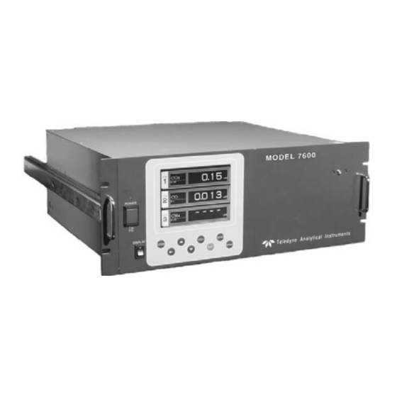
The concentration of the desired gases is displayed on a large, easy- to-read back-lit LCD. Figure 1-1 shows the standard rack mountable Model 7600. The user interface is very intuitive and the menu / mode selection buttons, which are readily accessible, provide the operator with dynamic control and extensive diagnostic capabilities. -
Page 16: Figure 1-1: Model 7600A Infrared Gas Analyzer
Introduction Model 7600 Figure 1-1: Model 7600A Infrared Gas Analyzer • Simultaneous measurement of up to five components • Excellent long-term stability • Large, easy to read LCD display showing all simultaneous measurements and computations • Slide-out, chassis design to facilitate any optical or... -
Page 17: Options Available
• Half-duplex bit serial • Modbus protocol 1.4 Applications The Model 7600 Infrared Gas Analyzer is a versatile analytical instrument tool and is ideally suited for multi-parameter gas analysis requirements for applications such as: • Combustion control within the power, pulp and paper, steel, and cement industries •... -
Page 18: Description Of The Main Unit
, CO, and CH in a gas mixture on a continuous basis. The Series 7600 can also be supplied with an oxygen sensor, which allows the simultaneous measurement of oxygen concentration as well. The NEMA-4 enclosure can be X or Z-purged to satisfy hazardous area installation requirements. -
Page 19: Figure 1-2: Model 7600 Description
Introduction Figure 1-2: Model 7600 Description Gas connections for the 7600 instrument are made on the rear panel of the instrument using the ¼” NPT fittings installed. The standard instrument has two measuring units and a pair of inlet/outlet gas connections exist for each unit. - Page 20 Introduction Model 7600 Teledyne Analytical Instruments...
-
Page 21: Installation
READ THIS CHAPTER IN ITS ENTIRETY BEFORE INSTALLING THE SYSTEM. FOR INDOOR USE ONLY. 2.1 Unpacking the Analyzer The Model 7600 Infrared Gas Analyzer is shipped with the following components: • 7600 Analyzer • Input/Output terminal module set • Connection cable •... -
Page 22: Choosing A Location
• Not exposed to direct sunlight. • Clean and non-cluttered space. • Depending on the options selected at the time of purchase, the model 7600 requires an AC power source of 100V to 240V AC. • Operating voltage: 85V to 264V AC •... -
Page 23: Mounting The Analyzer
Installation 2.3 Mounting the Analyzer The 19” rack mountable 7600 analyzer is designed for either a guide rail or slide rail mounting within a rack or cabinet. The guide rail method supports the weight of the instrument from the bottom and can be used when there is adequate space for removing the top cover for maintenance. -
Page 24: Figure 2-2: Input/Output Terminal Module
Installation Model 7600 mounting surface. Connect the panel to the same ground as the analyzer main unit. Figure 2-2: Input/Output Terminal Module Figure 2-3: Mounting the I/O Module Teledyne Analytical Instruments... -
Page 25: Gas Connections
Section 2.5.6 Purging the Analyzer. When required, use dry or instrumentation air for the purge gas. Use a flow rate of 1L/min or greater). 2.5.1 Internal Piping Diagram Note: When the purge gas inlet is provided, an internal connection to measuring unit 2 is installed. Teledyne Analytical Instruments... -
Page 26: Figure 2-4: Internal Piping With Single Or Dual Measuring Units
Installation Model 7600 An internal piping diagram for an instrument with one or two measuring units is shown in Figure 2-4. When there are two measuring units, if a built-in oxygen sensor is used, it must be installed in measuring unit 2. The diagram shows the combination of two cells used in measuring unit #2. -
Page 27: External Piping Diagram
Figures 2-6 and 2-7 are used when there are two pair of inlet/outlet connections. Note that a NO /NO converter is used when NO measurement is used for NOx analysis. Figure 2-5: External Piping with Single Inlet and Outlet Teledyne Analytical Instruments... -
Page 28: Gas Conditioning
Installation Model 7600 Figure 2-6: External Piping with Two Pair of Inlet/Outlet (1) Figure 2-7: External Piping with Two Pair of Inlet/Outlet (2) 2.5.3 Gas Conditioning For optimum performance, the sample gas should be treated as follows: • A filter should be installed to remove any dust or particles in the sample gas. -
Page 29: Flowrate
90% or more of 90% or more of full or more of full scale full scale scale Span gas for Gas concentration of 1 to 2% O analysis 90% or more of full scale Teledyne Analytical Instruments... -
Page 30: Purging The Analyzer
Figure 2-8. Contact Teledyne for specific application system configuration or further information. The system shown is comprised of: • Model 7600—with dual measuring unit option and external zirconia oxygen sensor. -
Page 31: Figure 2-8: Five Component Analysis System
• NO /NO Converter—added to the NO analysis circuit which uses an efficient catalyst for converting NO to NO for analysis. Figure 2-8: Five-Component Analysis System Teledyne Analytical Instruments... -
Page 32: Electrical Connections
2.6 Electrical Connections 2.6.1 Power Inlet The power inlet for the Model 7600 is located on the rear panel as shown in Figure 2-9. The proper 3-prong power cord has been supplied with your instrument. Connect the power cable to the power inlet. -
Page 33: Input/Output Terminal Module
Make sure that the ferrite core attached to the I/O cable goes to the analyzer. See Figures 2-9 and 2-11. Figure 2-11: I/O Cable Connection The I/O Module carries various input and output signals. A detailed list of these signals and pinout information is given in the Appendix. Teledyne Analytical Instruments... -
Page 34: Testing The System
Installation Model 7600 2.7 Testing the System After the analyzer has been installed with gas and electrical connections but prior to powering up the unit make sure you have: • Installed the unit correctly • Checked the gas connections for leaks... -
Page 35: Operation
3.1 General Information This section describes the front panel interface of the analyzer. Figure 3-1 Shows the Model 7600 Infrared Gas Analyzer front panel. The user interface consists of 8 membrane switch buttons or keys, a power ON/OFF switch and a display ON/OFF switch. The 8 user keys are shown in Figure 3-2 and described below. -
Page 36: Display And Available Menus
Used for spancalibration. 3.2 Display and Available Menus The display on the Model 7600 has two modes: measurement mode and user mode. To change between modes, press the MODE key. In the measurement mode, the display indicates the composition of the sample gas. -
Page 37: Figure 3-3: Display Modes And Menu Hierarchy
Infrared Gas Analyzer Operation Figure 3-3: Display Modes and Menu Hierarchy Teledyne Analytical Instruments... -
Page 38: The Display Screen
• Setting of Auto Calibration • Setting of Auto Zero Calibration • Setting of Peak Alarm • Parameter Setting Figure 3-3 shows the overall structure of the Model 7600 display and menu hierarchy. 3.3 The Display Screen 3.3.1 Measurement Mode The measurement mode screen is the default mode when the power is turned on. - Page 39 They are obtained from the following equation by setting sampling components, O instantaneous/ concentration values and O correction reference value (see item 6.8). ⎛ ⎞ × ⎜ ⎟ Correction output − ⎝ ⎠ Teledyne Analytical Instruments...
-
Page 40: Setting/Selection Screen
Operation Model 7600 Where: On: The value of the O correction reference value (Value set by application) Os: Oxygen concentration (%) Cs: Concentration of relevant measured component. Note that Os does not exceed the O limit value set in “Other Parameter”... -
Page 41: Basic Operation
ZERO or SPAN button. See Section 3.7 Calibration . User mode displays: In the user mode you can: • Switch ranges • Set calibration parameters • Adjust alarm settings Teledyne Analytical Instruments... -
Page 42: Setting Up The Analyzer In The User Mode
Operation Model 7600 • Set up the Auto Calibration feature • Setup an auto zero calibration • Adjust the peak alarm parameter Setting. These settings are described in Section 3.5. To enter the user mode from the measurement mode, press the MODE key. -
Page 43: Manual Range Switching
5. Then press the ENT key to confirm the selection. 3.5.1.1 M ANUAL ANGE WITCHING To manually switch between analysis ranges: 1. Select the MR option from the Switch Range screen and press the ENT key. Teledyne Analytical Instruments... -
Page 44: Range Identification Contact Operation
Operation Model 7600 2. Move the highlight of the cursor to range selection and select the desired range using the UP/DOWN keys. The highlighted arrow indicates the currently selected range. 3. Press ENT to accept the selection. Measurement is now carried out using the selected range. -
Page 45: Remote Range Selection
ENT. The selected range switch mode is highlighted for the channel you selected. Press the UP/DOWN keys to toggle between the available switch modes until RR is displayed. 5. Press the ENT key to accept the selection. Teledyne Analytical Instruments... -
Page 46: Autoranging
Model 7600 3.5.1.4 A UTORANGING The Model 7600 can be set to autorange where the instrument will select the analysis range automatically. To use the autorange feature, AR must be selected for the switch mode. Note that each channel is independent so that autoranging can be used for some or all of the available channels. - Page 47 DOWN key to increase or decrease a single digit. Select the next digit by pressing the SIDE key. 4. When the concentration is correct, save the entry by pressing the ENT key. The saved value becomes valid from the next calibration process. Teledyne Analytical Instruments...
-
Page 48: Setting Of Manual Zero Calibration
Operation Model 7600 Note: Enter settings that correspond to each range. If a zirconia type O sensor is used, select 21.00 for the field of Zero (when air is used), and select the concentration listed on the cylinder if the air contained in a cylinder is used. - Page 49 (see Section 3.7) and perform a zero calibration. Only that component is zeroed. • When the setting is “at once”, performing a manual calibration (see Section 3.7) will zero calibrate all components tagged “at once”. You will notice on the manual Teledyne Analytical Instruments...
-
Page 50: Setting Of Calibration Range
Operation Model 7600 zero calibration screen that all there are cursors on all components where “at once” is set. Note: When the cylinder air or atmospheric air is used for the zero gas, select “at once.” 3.5.2.3 S ETTING OF CALIBRATION RANGE Use the “About Calibration Range”... -
Page 51: Setting Of Auto Calibration Component/Range
Ch1 and Ch4 in the Manual Calibration screen shown below. 3.5.2.4 S ETTING OF AUTO CALIBRATION COMPONENT RANGE This menu is used to select the channel and the range in which auto calibration is to be performed. If a channel has been set to autoranging Teledyne Analytical Instruments... - Page 52 Operation Model 7600 (AR), it will be calibrated in the range set in this menu when auto calibration is performed. From this menu you can enable or disable the auto calibration feature. To navigate to the Auto Calibration Components/Range menu: 1.
-
Page 53: Alarm Setting
“enable”. 3.5.3 Alarm Setting The Model 7600 is equipped with 6 alarms (5 or 6 concentration and a power failure alarm). The alarm configuration and settings can be assigned to any channel and adjusted at any time by entering the user mode and navigating to the Alarm Setting submenu. - Page 54 Operation Model 7600 • High Limit: sets the upper value (concentration) above which the alarm will trigger. Has an on-screen display. • Low Limit: sets a lower value (concentration) below which the alarm will trigger. Has an on-screen display • High or Low Limit: triggers an alarm when the concentration is above the high limit or below the low limit.
-
Page 55: Configuring The Alarms
3. In the “Alarm Setting” screen that appears, point the cursor to the alarm number you want to set (1 through 6) using the UP or DOWN key. Press the ENT key when the cursor is on the alarm number you desire. Teledyne Analytical Instruments... -
Page 56: Hysteresis Setting
Operation Model 7600 4. The alarm item selection screen will appear where you can select the alarm type, assign it to a channel, define setpoints, and enable or disable the alarm. Use the UP or DOWN keys until the cursor is aligned with the desired function and press the ENT key. -
Page 57: Figure 3-6: Hysteresis Example For A High Limit Alarm
2. In the “Hysteresis Value Setting” screen that appears, enter hysteresis values using the UP or DOWN keys to increment or decrement a digit. Use the SIDE key to move to the next digit. When finished, press ENT. Teledyne Analytical Instruments... -
Page 58: Setting Of Auto Calibration
Operation Model 7600 To close the “Hysteresis Setting” or cancel the mode midway, press the ESC key. A previous screen will return. 3.5.4 Setting of Auto Calibration 3.5.4.1 A ALIBRATION Auto calibration is automatically carried out when zero and span calibrations are set. -
Page 59: Gas Flow Time Setting
ESC key. A previous screen will return. 3.5.4.2 G ETTING In this submenu you select the gas whose flow time is to be changed. The flow time range is from 60 to 900 seconds. The initial value is set for 300 seconds. Teledyne Analytical Instruments... -
Page 60: Cycle Setting Range
Operation Model 7600 To set the flow time: 1. Place the cursor next to “Flow Time,” then press the ENT key. 2. On the flow time setting screen that appears, use the UP and DOWN keys to move the cursor to the gas whose settings you want to change, then press ENT. -
Page 61: Figure 3-7: Example Auto Calibration
350 sec Ch1 Span 350 sec Ch1 Span 350 sec Ch1 Span 300 sec Ch1 Span 300 sec EX. time 300 sec ON/OFF Figure 3-7 shows the auto calibration with the above settings. Figure 3-7: Example Auto Calibration Teledyne Analytical Instruments... -
Page 62: Remote Start
Operation Model 7600 When a channel enabled for auto calibration is in the calibration mode, a message indicating ZERO cal. or SPAN cal. will appear on the measurement screen. For example, if channels 1 and 2 have the auto calibration setting enabled, when the calibration event takes place, both channels 1 and 2 will indicate ZERO cal. - Page 63 4. “Run” is highlighted, displaying a message to confirm the execution of auto calibration. Press the ENT key to execute the auto calibration, or press the ESC key to cancel. 3.5.4.5.2 F ORCIBLY ND AN ALIBRATION To abort an auto calibration event: Teledyne Analytical Instruments...
- Page 64 Operation Model 7600 5. From the measurement mode, press the MODE key to display the user mode. 6. Point the cursor to “Setting of Auto Calibration” by pressing the UP or DOWN key and press the ENT key. 7. In the “Setting of Auto Calibration” item selection screen that appears, point the cursor to “Auto Calibration Run”...
-
Page 65: Setting Of Auto Zero Calibration
To change the settings: 1. From the measurement mode, press the MODE key to display the user mode. 2. Point the cursor to “Setting of Auto Zero Calibration” by pressing the UP or DOWN key and press the ENT key. Teledyne Analytical Instruments... - Page 66 Operation Model 7600 In the “Setting of Auto Zero Calibration” screen that appears, point the cursor to any item you want to set by UP or DOWN pressing the key. Press the ENT key. 4. In the “Auto Zero Calibration Parameter Setting” screen that appears, perform the value entry or the setting.
-
Page 67: Figure 3-8: Example Auto Zero Calibration
Turn on the power again after it is turned off (including the case of power failure) at the time set as the next start time in auto zero calibration, and then repeat it in the set cycle. Teledyne Analytical Instruments... -
Page 68: Forced Run/Stop Of Auto Zero Calibration
Operation Model 7600 3.5.5.2 F ORCED RUN STOP OF AUTO ZERO CALIBRATION Like the auto calibration, the auto zero calibration can be performed manually or forcibly stopped while the calibration is performed. 3.5.5.2.1 M ANUAL XECUTION OF UTO ZERO ALIBRATION To perform the auto calibration cycle manually: 1. - Page 69 Press the ENT key. 4. “Stop” is highlighted, displaying a message to confirm the stop of auto calibration. Press the ENT key to stop the auto calibration, or press the ESC key to cancel the abort. Teledyne Analytical Instruments...
-
Page 70: Peak Alarm Setting
Operation Model 7600 Note: During auto zero calibration, the keys are inoperable other than key lock ON/OFF and “Stop Auto Zero Calibration.” When the key lock is set to ON, even the “Auto Zero Calibration Stop” is locked out. To stop “Auto Zero Calibration”... - Page 71 If measuring value exceeds the set alarm value in ppm, a peak counter increments by 1. Alarm Count: When a peak in excess of the alarm value occurs, a peak count is incremented. The alarm count is Teledyne Analytical Instruments...
-
Page 72: Figure 3-9: Peak Alarm Example
Operation Model 7600 the numerical value which upon reaching will trigger the peak alarm. Hysteresis: To prevent possible chattering when the measuring value may exceed the set peak concentration by only 1 time, the peak count has an allowance in the hysteresis width. -
Page 73: Parameter Setting
Key Lock: Sets with ON/OFF. When set to ON, all key operations except key lock OFF are disabled. Output Hold: Sets whether calibration output is held or not, and the holding value setting. Teledyne Analytical Instruments... -
Page 74: Model
Operation Model 7600 Reset Av. Output: Resets the average value. Response time: Sets the response time of the electrical system. Average Period: Sets the moving average time. Backlight Timer: Sets an automatic OFF of the backlight of display unit and the time until the backlight is turned OFF. -
Page 75: Output Hold
3.5.4, Setting of Auto Calibration for a description of the gas flow time. Regardless of Hold ON/OFF setting, an output signal can always be held via an external input. Manual calibration Figure 3-10: Output Hold for Manual Calibration Teledyne Analytical Instruments... -
Page 76: Figure 3-11: Output Hold For Auto Calibration
Operation Model 7600 Auto calibration Figure 3-11: Output Hold for Auto Calibration External hold Figure 3-12: Output Hold for External Hold Screen display during hold For Auto calibration and external holds, the “on Hold” message will be shown blinking on the measurement screen. - Page 77 “Current” or “Setting”. Select “Setting” by pressing the UP or DOWN key until that option appears then press ENT. The screen changes to the hold setting screen where you can select the channel and hold value for that channel. Teledyne Analytical Instruments...
-
Page 78: Average Value Reset
Operation Model 7600 5. On the parameter hold screen that appears, move the cursor next to the channel you want to make the setting by pressing the UP or DOWN key, and then press ENT. The value is highlighted, indicating that the value can be changed. -
Page 79: Response Time
3.5.7.4 A VERAGE ERIOD This submenu allows you to set an averaging period over which the average value of O correction and O average are sampled. Teledyne Analytical Instruments... -
Page 80: Backlight Timer
Operation Model 7600 To modify the average period: 1. Choose the channel or channels you want to modify. You can set an average time from 1 to 59 minutes in 1-minute steps or 1 to 4 hours in 1-hour steps. -
Page 81: Maintenance Mode
To enter the maintenance mode: 1. From the measurement screen press the MODE key to open the user mode screen. Teledyne Analytical Instruments... -
Page 82: Maintenance Mode
Operation Model 7600 2. Select Parameter Setting from the user screen. 3. With the UP or DOWN key, select Maintenance Mode and press ENT. 3.6 Maintenance Mode This mode is used for checking sensor input values, error log file display, or setting of passwords, etc. A password is required to enter this mode. -
Page 83: Sensor Input Value
NOx M: NOx sensor input value NOx C: NOx interference compensation sensor input value M: SO sensor input value C: SO interference compensation sensor input value M: CO sensor input value C: CO interference compensation sensor input value Teledyne Analytical Instruments... -
Page 84: Error Log
Operation Model 7600 CO M: CO sensor input value CO C: CO interference compensation sensor input value Temperature: temperature sensor input value O sensor input value 3.6.2 Error Log This screen gives the error history for the last fourteen logged errors. -
Page 85: Optical Adjustment
AFFECTED. CARRY OUT THE OPERATION WITH UTMOST ATTENTION. For details of this item, refer to Section4.4 Optical Zero Adjustment. Press ENT key and then turn ON the solenoid valve signal for each calibration gas by using the UP or DOWN keys. Teledyne Analytical Instruments... -
Page 86: Moisture Interference Adjustment
Operation Model 7600 3.6.5 Moisture Interference Adjustment This item is described in Section 4.5 Moisture Interference Adjustment . For the values listed in the middle column of the screen, the moisture interference for each component is already offset. The values in the right column are the interference compensation coefficients used. -
Page 87: Other Parameters
19%. • Limit: Set the oxygen concentration limit at the time of oxygen correction calculation. Settable in the range from 01 to 20%. See correction concentration value in Section 3.3.1 Measurement Mode for oxygen correction calculation procedure. Teledyne Analytical Instruments... - Page 88 Operation Model 7600 • Station No.: Set the station No. for MODBUS communication. Settable in the range from 00 to 32. • Range setting: Moves to the screen on which measuring range is changed. To adjust or make changes to these parameters: 1.
- Page 89 SIDE key to select the next digit. When the decimal point is highlighted, press the UP or DOWN key, and the decimal point position can be changed. 5. When complete, press the ENT key to save the change. Teledyne Analytical Instruments...
-
Page 90: Calibration
Operation Model 7600 3.7 Calibration 3.7.1 Zero Calibration The zero calibration is used for zero point adjustment. A suitable zero calibration gas is described in Section 2.5.5 Preparation of Calibration Gas . To zero calibrate the analyzer: 1. Press the ZERO key on the Measurement screen to display the Manual Zero Calibration screen. -
Page 91: Span Calibration
Note: If the selected channel was set for autoranging “AR” (see Section 3.5.1 Switch Ranges. the cursor automatically moves to the range selected in “Setting of Auto Calibration Component/ Range” (Section 3.5.2.4), and calibration is carried out within that range. Teledyne Analytical Instruments... - Page 92 Operation Model 7600 To close "Span Calibration" To close the “Span Calibration” screen or cancel this mode midway, press the ESC key. A previous screen will return. Teledyne Analytical Instruments...
-
Page 93: Maintenance
Table 4.1 Troubleshooting and Maintenance Item to be Phenomena Cause Remedy checked Display value Display values are (1) Dust is (1) Clean the low. mixed in sampling cell. sampling cell. Display values are Check high. sampling system especially gas filter. Teledyne Analytical Instruments... -
Page 94: Analyzer Maintenance
Maintenance Model 7600 Item to be Phenomena Cause Remedy checked (2) Air is (2) Find cause absorbed of leak and midway in the repair. sampling pipe. Purge gas flow is Standard flow is Adjust using included when beyond the specified... -
Page 95: Figure 4-1: Top Cover Removal
CAUTION: THE WINDOW IS EASILY SCRATCHED. USE EXTREME CARE WHEN PERFORMING THIS OPERATION SO AS NOT TO DAMAGE IT. Figure 4-1: Top Cover Removal Figure 4-2: Sample Cell Removal Teledyne Analytical Instruments... -
Page 96: Figure 4-3: Sample Cell
Maintenance Model 7600 Figure 4-3: Sample Cell Teledyne Analytical Instruments... -
Page 97: Cleaning The Cell Block
2. Loosen the 2 setscrews that secure the top cover and remove it. 3. Remove the internal gas inlet tube. 4. Loosen the 2 detector set bolts. See Figure 4-5. Note: The gas distribution block, cell block, and detector are fastened by the same bolts. Teledyne Analytical Instruments... -
Page 98: Figure 4-5: Detector Secure Nut
Maintenance Model 7600 Figure 4-5: Detector Secure Nut 5. Using the furnished cell mounting tool, turn the window fixture to the left and remove it from the cell. See Figure 4-6. 6. For cleaning the infrared transmission window and cell inside surface, first eliminate coarse dust using a soft brush and then wipe clean with a soft rag. -
Page 99: Optical Zero Adjustment
The following adjustment is performed at reassembly after removing and cleaning the sample cell. 1. Remove the top cover. 2. Allow dry N or air to flow through the analyzer sample gas inlet until the reading stabilizes. The sample gas is Teledyne Analytical Instruments... -
Page 100: Figure 4-7: Optical Adjustment Display For Dual Optical System Option
Maintenance Model 7600 introduced directly to the inlet of analyzer unit through the gas cylinder. 3. Proceed to an optical adjustment as described in the maintenance mode. The display on the operation panel of the main unit is illustrated in Figure 4-7. Balance adjust- ment is not required if the display falls within ±100. -
Page 101: Figure 4-8: Optical Zero Adjustment
6. Operate the optical zero adjustment knob to change the value displayed at (a) or (e). See Figure 4-8 Figure 4-8: Optical Zero Adjustment 7. Move the beam adjustment plate sideways to change the value displayed at (b) or (f ). See Figure 4-9. Teledyne Analytical Instruments... -
Page 102: Moisture Interference Compensation Adjustment
Maintenance Model 7600 Figure 4-9: Beam Adjustment Plate 8. Move the beam adjustment plate sidewise to change the value displayed at (c) or (g). 9. Move the beam adjustment plate sidewise to change the value displayed at (d) or (h). -
Page 103: Figure 4-10: Bubbler Apparatus
4. Use the SIDE key to move the cursor to the numerical value in the right column. Adjust the value by the UP or DOWN key so that the value at left falls within ±10 (or as Teledyne Analytical Instruments... -
Page 104: Error Messages
Maintenance Model 7600 close to 0 as possible), and then press the ENT key to save the value. Alternatively, by selecting the “ALL”option and pressing the “ ENT ” key, you can zero all components at once. You can abort the process at any time by pressing the “... - Page 105 When errors No. 4 to No. 9 occur, calibration error contact is closed. When an error occurs, the error number message will appear at the offending channel. The screen below shows that error No. 9 has occurred on Channel 1. Teledyne Analytical Instruments...
-
Page 106: Error Log File
Maintenance Model 7600 Pressing ENT displays the error contents screen which describes the error, indicates what channel or component is affected and suggests probable causes for the error. If the ESC key is pressed without removing the cause of an error, the error will be displayed again. -
Page 107: Deleting Error Hstory
If the power supply is turned OFF, the contents in the error log file will not be lost or damaged. 4.6.3 Deleting Error Hstory Press the ENT key on the above screen, and the “Error Log Clear” will be inverted. Pressing the ENT key again will clear the error history. Teledyne Analytical Instruments... - Page 108 Maintenance Model 7600 Teledyne Analytical Instruments...
-
Page 109: Appendix
(NO, SO , CO , CO): Non-dispersion infrared-ray absorption Single light source and double beam (double-beam system) : Paramagnetic O2 sensor (built in) or zir conia O2 sensor (externally installed) Display: 4-digit digital LCD display with back light Teledyne Analytical Instruments... - Page 110 Appendix Model 7600 Analog Output: 12 points max. 4 to 20 mA DC or 0 to 1V DC, non- isolated output max.load 550Ω for 4 to 20 mA DC min.load 100kΩ for 0 to 1VDC Analog Input: 0 to 1V DC non-isolated input from externally installed Zirconia type O sensor.
-
Page 111: Standard Functions
Selectable. Indication of instantaneous values will not be held. Output signal is held at the latest value or Remote output holding: setting value by short-circuiting the remote output holding input terminals. Holding is maintained while the terminals Teledyne Analytical Instruments... - Page 112 Appendix Model 7600 are short-circuited. Indication of instanta- neous values will not be held. Range switching is available in manual, Range switching: auto, and remote modes. Only preset switch method is effective. Manual: Allows range to switch by key operation.
- Page 113 Auto zero calibration cycle setting: Auto zero calibration cycle is set. Teledyne Analytical Instruments...
- Page 114 Appendix Model 7600 Setting is variable within 1 to 99 hours (in increments of 1 hour) or Setting is variable within 1 to 40 days (in increments of 1 day) Gas flow time setting: The timing for flowing zero gas in auto zero calibration is set.
-
Page 115: Optional Functions
Average value resetting: The above-mentioned output of average value is started from the initial state by opening the average value resetting input terminals after short-circuiting for 1.5 sec- onds or longer. Output is reset by short-circuiting and re- started by opening Teledyne Analytical Instruments... -
Page 116: Performance
Appendix Model 7600 CO concentration peak count alarm: (added only for CO/O measurement) Alarm output turns on according to the pre-set concentration and count. Whenever the instantaneous value of CO exceeds the preset concentration value, count increments. If the count exceeds the preset value in one hour, the alarm contacts close. -
Page 117: Standard Requirements For Sample Gas
Zero gas: Dry air or atmospheric air (provided without CO sensor). Span gas: For other than O measurement, each sample gas having concentration 90 to 100% of its measuring range. For O measurement: O gas of 1 to 2 vol Teledyne Analytical Instruments... -
Page 118: Installation Requirements
Appendix Model 7600 A.6 Installation Requirements • Indoor use. Select a place where the equipment does not receive direct sunshine, draft/rain or radiation from hot substances. If such a place cannot be found, a roof or cover should be prepared for protection. -
Page 119: Terminal Block Connections
Infrared Gas Analyzer Appendix A.8 Terminal Block Connections Teledyne Analytical Instruments... -
Page 120: Description On Terminal Block
Appendix Model 7600 A.9 Description on Terminal Block Teledyne Analytical Instruments... - Page 121 Infrared Gas Analyzer Appendix Teledyne Analytical Instruments...
- Page 122 Appendix Model 7600 Teledyne Analytical Instruments...
- Page 123 Infrared Gas Analyzer Appendix Teledyne Analytical Instruments...
- Page 124 Appendix Model 7600 Teledyne Analytical Instruments...
-
Page 125: Index
33 warning sign, iv leak check, 33 warranty, ii manuals, additional, v website address, v Teledyne Analytical Instruments... - Page 126 Index Model 7600 Teledyne Analytical Instruments...
Need help?
Do you have a question about the 7600 and is the answer not in the manual?
Questions and answers