Table of Contents
Advertisement
Quick Links
OPERATING INSTRUCTIONS
Model
Infrared Gas Analyzer
HIGHLY TOXIC AND OR FLAMMABLE LIQUIDS OR GASES MAY BE PRESENT IN THIS MONITORING SYSTEM.
PERSONAL PROTECTIVE EQUIPMENT MAY BE REQUIRED WHEN SERVICING THIS SYSTEM.
HAZARDOUS VOLTAGES EXIST ON CERTAIN COMPONENTS INTERNALLY WHICH MAY PERSIST FOR A
TIME EVEN AFTER THE POWER IS TURNED OFF AND DISCONNECTED.
ONLY AUTHORIZED PERSONNEL SHOULD CONDUCT MAINTENANCE AND/OR SERVICING. BEFORE
CONDUCTING ANY MAINTENANCE OR SERVICING CONSULT WITH AUTHORIZED SUPERVISOR/MANAGER.
Teledyne Analytical Instruments
7300A
DANGER
Infrared Gas Analyzer
P/N M00000
10/13/00
ECO # 00-0000
i
Advertisement
Table of Contents
Troubleshooting

Related Manuals for Teledyne 7300A


Summary of Contents for Teledyne 7300A
-
Page 1: Operating Instructions
HAZARDOUS VOLTAGES EXIST ON CERTAIN COMPONENTS INTERNALLY WHICH MAY PERSIST FOR A P/N M00000 TIME EVEN AFTER THE POWER IS TURNED OFF AND DISCONNECTED. 10/13/00 ONLY AUTHORIZED PERSONNEL SHOULD CONDUCT MAINTENANCE AND/OR SERVICING. BEFORE ECO # 00-0000 CONDUCTING ANY MAINTENANCE OR SERVICING CONSULT WITH AUTHORIZED SUPERVISOR/MANAGER. Teledyne Analytical Instruments... - Page 2 Any safeguards required such as locks, labels, or redundancy, must be provided by the user or specifically requested of Teledyne at the time the order is placed.
- Page 3 RANGE 2: FROM____________ TO___________ % / PPM (circle one) RANGE 3: FROM____________ TO___________ % / PPM (circle one) RANGE 4: FROM____________ TO___________ % / PPM (circle one) FILTER: __________________ CALIB_FACTOR: __________________ HARD_OFFSET_C: __________________ HARD_OFFSET_F: __________________ SOFTWARE VERSION: ____________ SERIAL #: __________________ Teledyne Analytical Instruments...
- Page 4 Model 7300A Teledyne Analytical Instruments...
- Page 5 Table of Contents OPERATING INSTRUCTIONS 7300A Model Infrared Gas Analyzer Table of Contents General Purpose Teledyne Analytical Instruments...
-
Page 6: Table Of Contents
Model 7300A Infrared Gas Analyzer Table of Contents 1 Introduction 1.1 Overview ................ 1-1 1.2 Typical Gas Applications ..........1-1 1.3 Main Features of the Analyzer ........1-2 1.4 General ................1-3 1.5 NDIR Analyzer ............... 1-3 2 Installation 2.1 Unpacking the Analyzer ..........2-1 2.2 Installing &... - Page 7 4.3.10 Zero Offset Adjustment .......... 4-13 4.3.11 CAL-OUT Funtion ..........4-14 4.4 The Zero and Span Functions ........4-16 4.4.1 Zero Cal ..............4-16 4.4.1.1 Auto Mode Zeroing ........4-17 3.4.1.2 Manual Mode Zeroing ........4-18 3.4.1.3 Cell Failure ............ 4-18 Teledyne Analytical Instruments...
- Page 8 Model 7300A Infrared Gas Analyzer 4.4.2 Span Cal ..............4-19 4.4.2.1 Auto Mode Spanning ........4-19 4.4.2.2 Manual Mode Spanning ......... 4-20 4.5 The Alarms Function ............4-21 4.6 The Range Select Function ........... 4-23 4.6.1 Manual (Select/Define Range) Screen ....4-23 4.6.2 Auto Screen ............
-
Page 9: Introduction
The manual covers the Model 7300A General Purpose 19” Panel/Rack mounted analyzer. Consisting of an Analysis section and Control Unit section. The 7300A Analyzer is for indoor or protected use in General Purpose environments only. Typical Gas Applications... -
Page 10: Main Features Of The Analyzer
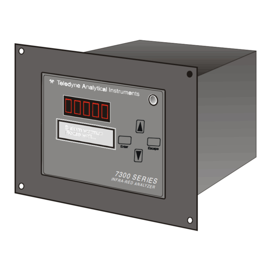
1 Introduction Model 7300A Main Features of the Analyzer The Model 7300A Infrared Gas Analyzer is sophisticated yet simple to use. The main features of the analyzer include: • A easy-to-use front panel interface that includes a red 5-digit LED display and a vacuum fluorescent display, driven by microprocessor electronics, that continuously prompts and informs the operator. -
Page 11: Ndir Analyzer
NDIR Analyzer The Model 7300A contains an optical system consisting of an infrared (IR) source, sample cell, and detectors. In front of the thermopile detectors are four interference-type filters. These filters are designated the reference and measuring filters. - Page 12 1 Introduction Model 7300A Teledyne Analytical Instruments...
-
Page 13: Installation
32°F nor rise above 100°F. In areas outside these temperatures, auxillary heating/cooling must be supplied. The 7300A enclosure is oil and dust resistant though designed to resist moisture, must not be considered completely water-tight. Mounting to walls or racks must be made securely. -
Page 14: Iuser Connections
2 Installation Model 7300A placed as close to the sample point as possible and bolted to its supporting surface. When installed as a system with enclosure (non-panel or rack mounted) a waterproof mastic should be liberally applied to the under surfaces of all supporting legs of the cubicle system before placing it in position and bolting it in place. -
Page 15: Pipe Connection
Electrical Connections (Rear Panel) Figure 3-3 shows the Model 7300A rear panel. There are connectors for power, digital communications, and both digital and analog concentration output. -
Page 16: Primary Input Power
2 Installation Model 7300A 2.3.1 Primary Input Power The power cord receptacle and fuse block are located in the same assembly. Insert the power cord into the power cord receptacle. DANGER: POWER IS APPLIED TO THE INSTRUMENT'S CIR- CUITRY AS LONG AS THE INSTRUMENT IS CON- NECTED TO THE POWER SOURCE. - Page 17 For example, if the analyzer is set on a range that was defined as 0–10 % carbon monoxide, then the output would be as shown in Table 2-3. Table 2-3: Analog Concentration Output—Example Percent Voltage Signal Current Signal Output (V dc) Output (mA dc) 10.4 12.0 Teledyne Analytical Instruments...
-
Page 18: Alarm Relays
2 Installation Model 7300A 13.6 15.2 16.8 18.4 20.0 To provide an indication of the range, the Range ID analog outputs are used. They generate a steady preset voltage (or current when using the current outputs) to represent a particular range. Table 2-4 gives the range ID output for each analysis range. -
Page 19: Digital Remote Cal Input
A synchronous signal must open and close the gas control valves appropriately. Cal Contact: This relay contact is closed while analyzer is spanning and/or zeroing. (See Remote Calibration Protocol below.) Teledyne Analytical Instruments... - Page 20 Cal Contact Cal Contact Remote Calibration Protocol: To properly time the Digital Remote Cal Inputs to the Model 7300A Analyzer, the customer's controller must monitor the Cal Relay Contact. When the contact is OPEN, the analyzer is analyzing, the Remote Cal Inputs are being polled, and a zero or span command can be sent.
-
Page 21: Range Id Relays
Pins 13 (+) and 29 (–). 2.3.3.6 Remote Valve Connector The 7300A is a single-chassis instrument, which has no Remote Probe Unit. Instead, the Remote Valve connector is used as another method for controlling external sample/zero/span gas valves. See Figure 2-5. -
Page 22: Rs-232 Port
2 Installation Model 7300A The voltage from these outputs is nominally 0 V for the OFF and 15 V dc for the ON conditions. The maximum combined current that can be pulled from these output lines is 100 mA. (If two lines are ON at the same time, each must be limited to 50 mA, etc.) If more current and/or a different... -
Page 23: Gas Requirements
RS-232, until st<enter> is sent again. Implementation: The RS-232 protocol allows some flexibility in its implementation. Table 2-9 lists certain RS-232 values that are required by the Model 7300A implementation. Table 2-9: Required RS-232 Options Parameter Setting Baud... -
Page 24: Testing The System
2 Installation Model 7300A Testing the System Before plugging the instrument into the power source: • Check the integrity and accuracy of the fluid connections. Make sure there are no leaks. • Check the integrity and accuracy of the electrical connections. - Page 25 Refer to the span procedure in section 4.4.2. (Note: The span gas should typically be an 80% of full scale range gas similar to the 100% zero gas background; i.e., 100% CO zero gas and a span gas of 98.4% CO2 in N2 for a 98-100%CO2 purity application. Teledyne Analytical Instruments 2-13...
- Page 26 2 Installation Model 7300A 2-14 Teledyne Analytical Instruments...
-
Page 27: Start-Up And Theory Of Operation
3.2.1 Initial Set-up and Zeroing Assure the sample will enter from the zero inlet gas position. Open the zero gas tank and set the pressure regulator to 20 psig. Set the zero gas flow Teledyne Analytical Instruments... -
Page 28: Operational Calibration
3 Start-up and Theory of Operation Model 7300A and sample flow between 0.1 to 0.6 SCFH (50-250 cc/min) . Zero standard gas must have a composition similar to sample, an ideally, contains none of the components of interest. Initialize a zero operation through the system menu. Refer to Section 4 for Electronics /Control Unit Modes and Functioning to navigate the zero menu. -
Page 29: Theory Of Operation
An electronics system to process the changes in the electronic resistance of the detector, and to convert these changes into specific electronics signals that deliver a voltage at current linearly proportional to the concentration of the gas measured. The Teledyne NDIR analyzer employs all of the above features. 3.3.2 Analyzer The emitted IR energy is generated by one specially configured miniature lamps in parabola’s focused and operating at low power of only 0.5 watts. - Page 30 E xtern al Valve C ontrol R em ote Sp an C ontrol Pow er R em ote Zero A to D C onv S upply C ontrol C al C ontact Block Diagram of the Model 7300A Electronics Teledyne Analytical Instruments...
-
Page 31: Circuit Description
Start-up and Operation 3.4 Circuit Description The Teledyne Analytical Instruments IR bench is a multiple wave- length, single beam design. It uses a quadruple detector that consists of a specially designed, patented thermopile with small IR filters mounted in front of it to produce independent voltages. -
Page 32: Digital Signal Processing & Electronics
Usually the output is between 0.2 and 0.9 mVDC. The Teledyne detector consists of four detec- tors: A, B, C and D. They are strapped to the inputs of the positive, very high-gain amplifiers U1, U2, U3, and U4. -
Page 33: Linearizer
In order to produce a linear signal response, a compensation curve is required (see Figure II). Therefore, a linearizer software routine is included to create a linear response. Refer to section 4.3.7 and 4.8.2 to see how linearizer is programmed. Teledyne Analytical Instruments... - Page 34 3 Start-up and Theory of Operation Model 7300A Figure II Linearizer Input Piece-wise approximation is the method used to linearize the signal, i.e., the linearizer’s output to input relationship can be graphed as a number of straight line segments connected together to approximate the desired curve...
-
Page 35: Automatic Function
2. The Auto Zero solenoid valve (optional) is activated and zero gas replaces the sample. (This valve may be internal or external to the Model 7300A enclosure). 3. At about minute one in the cycle. The Auto Zero board then begins its zeroing function, adjusting the processing circuitry of the analyzer to develop a zero signal output. - Page 36 3 Start-up and Theory of Operation Model 7300A 3-10 Teledyne Analytical Instruments...
-
Page 37: Introduction
Set output reversal. • Set polarity reversal or offset output.S • Set gain amplification. Before you configure your 7300A, the following default values are in effect: RANGE/APPLICATIONS: refer to data sheet on the first page of this manual; Range: Manual Alarm Relays: Defeated, 0.00%, HI, NOT Fail/Safe, not latching... -
Page 38: Using The Controls
4 Operation Model 7300A Using the Controls To get the proper response from these controls, press the desired key (ESCAPE or ENTER—DOWN or UP). To enter the screen menu, press any key. The item that is between arrows on the screen is the item that is currently selectable by pressing the ENTER enter key. -
Page 39: Setup Mode
Version SELF-TEST SPAN ZERO ALARMS RANGE Troublsho- HARDW-VAR oting Data Set Digital FILTER Filter CAL- Calibrate Analog OUTPUT Output APPLICATION Enter ALOGORITHM Enter Set Zero OFFSET Offset Enter CAL-INDPD STAND-BY Figure 4-1: Hierarchy of Functions and Subfunctions Teledyne Analytical Instruments... - Page 40 The MAIN MENU consists of 14 functions you can use to customize and check the operation of the analyzer. Figure 4-1 shows the functions available with the 7300A. They are listed here with brief descriptions: 1 AUTO-CAL: Used to define and/or start an automatic calibration sequence.
-
Page 41: Data Entry
When the last field is entered, ENTER takes you to the next screen in the process, or if the process is completed, ENTER takes you back to the ANA- LYZE screen. 4.2.2.2 ESCAPE Pressing the ESCAPE key takes you back to the previous screen. Teledyne Analytical Instruments... -
Page 42: Enter
Note: If you require highly accurate AUTO-CAL timing, use external AUTO-CAL control where possible. The internal clock in the Model 7300A is accurate to 2-3 %. Accordingly, internally scheduled calibrations can vary 2-3 % per day. Note: If your ranges are configured for different applications, then AUTO-CAL will calibrate all of the ranges simultaneously (by calibrating the Cal Range). -
Page 43: Password Protection
UP or DOWN key to change the letters to the proper password. The last ENTER enters the password. In a few seconds, you will be given the opportunity to change this pass- word or keep it and go on. Teledyne Analytical Instruments... -
Page 44: Installing Or Changing The Password
4 Operation Model 7300A Press Escape to move on, or proceed as in Changing the Password, below. 4.3.3.2 Installing or Changing the Password If you want to install a password, or change an existing password, proceed as above in Entering the Password. When you are given the opportunity to... -
Page 45: Logging Out
LOGOUT function, and ENTER to logout The screen will display the message: 4.3.5 System Self-Diagnostic Test The Model 7300A has a built-in self-diagnostic testing routine. Prepro- gramming signals are sent through the power supply, output board, preamp board and sensor circuit. The return signal is analyzed, and at the end of the test... -
Page 46: The Model Screen
4 Operation Model 7300A The self diagnostics are run automatically by the analyzer whenever the instrument is turned on, but the test can also be run by the operator at will. To initiate a self diagnostic test during operation, use the UP/DOWN key to scroll through the MAIN MENU to the and Enter. -
Page 47: Troubleshooting Information
= 492 (This is the current zero offset from the zero calibration of the gain and range the instrument is on at the moment. It should be between 10,000 to 10,000) Teledyne Analytical Instruments 4-11... -
Page 48: Digital Flter Setup
4.3.9 Digital Filter Setup The 7300A analyzer has the option of decreasing or increasing the amount of filtering on the signal. This feature enhances the basic filtering done by the analog circuits by setting the amount of digital filtering effected by the micro- processor. -
Page 49: Zero Offset Adjustment
If you chose MANual zero mode, then you must adjust the zero of the instrument the corresponding section of the manual but with one difference: instead of bringing the display to read zero, you must make the display read zero plus the value entered as offset. Teledyne Analytical Instruments 4-13... -
Page 50: Cal-Out Funtion
1. Let the intended zero calibration gas flow through the 7300A sample cell (this assumes that you have started up your system as recommended by the manual or technical personnel) and do a zero on the instrument. - Page 51 If instrument is cold started (returned to factory settings) the settings will be returned to 0 and non-NAMUR NE43 compliant. NOTE: Analog 0-1 vdc output does not get calibrated when 4 to 20 madc is adjusted, due to errors introduced by its own electronics. Teledyne Analytical Instruments 4-15...
-
Page 52: The Zero And Span Functions
Model 7300A The Zero and Span Functions (1) The Model 7300A can have as many as three analysis ranges plus a special calibration range (Cal Range); and the analysis ranges, if more than one, may be programmed for separate or identical gas applications. -
Page 53: Auto Mode Zeroing
Analyze . Software zero is indicated by in the lower right corner. The zeroing process will automatically conclude when the output is within the acceptable range for a good zero. Then the analyzer automatically returns to the Analyze mode. Teledyne Analytical Instruments 4-17... -
Page 54: Manual Mode Zeroing
Cell failure in the 7300A is usually associated with inability to zero the instrument with a reasonable voltage differential across the Wheatstone bridge. If this should ever happen, the 7300A system alarm trips, and the VFD displays a failure message. -
Page 55: Span Cal
Use the UP/ DOWN key to toggle between span settling. Stop when appears, blinking, on the display. Enter to move to the next screen. Use UP/DOWN key to change the span setting value. Teledyne Analytical Instruments 4-19... -
Page 56: Manual Mode Spanning
4 Operation Model 7300A ENTER will move the blinking field to units (%/ppm). Use UP/DOWN key to select the units, as necessary. When you have set the concentration of the span gas you are using, Enter to begin the Span calibration. -
Page 57: The Alarms Function
Analyze function. The Alarms Function The Model 7300A is equipped with 6 fully adjustable set points concentra- tion with two alarms and a system failure alarm relay. Each alarm relay has a set of form “C" contacts rated for 3 amperes resistive load at 250 V ac. See Figure in Chapter 3, Installation and/or the Interconnection Diagram included at the back of this manual for relay terminal connections. - Page 58 4 Operation Model 7300A alarm status will terminate when process conditions revert to non- alarm conditions. 4. Are either of the alarms to be defeated? The defeat alarm mode is incorporated into the alarm circuit so that maintenance can be performed under conditions which would normally activate the alarms.
-
Page 59: The Range Select Function
The Manual range-switching mode allows you to select a single, fixed analysis range. It then allows you to redefine the upper and lower limits, for the range. Use UP/DOWN key to start the RANGE function, and ENTER Teledyne Analytical Instruments 4-23... -
Page 60: Auto Screen
4 Operation Model 7300A Note: If all three ranges are currently defined for different applica- tion gases, then the above screen does not display (because mode must be manual). Instead, the VFD goes directly to the following screen. If above screen displays, use the UP/DOWN arrow keys to Select , and press Enter. -
Page 61: Precautions
Enter. Press Escape to return to the previous Analyze Function. 4.6.3 Precautions The Model 7300A allows a great deal of flexibility in choosing ranges for automatic range switching. However, there are some pitfalls that are to be avoided. Ranges that work well together are: •... -
Page 62: The Analyze Function
4 Operation Model 7300A • Ranges that overlap • Ranges whose limits are entirely within the span of an adjoining range. Figure 4-2 illustrates these schemes graphically. Figure 4-2: Examples of Autoranging Schemes The Analyze Function Normally, all of the functions automatically switch back to the Analyze function when they have completed their assigned operations. -
Page 63: Programming
Normally the Model 7300A is factory set to default to manual range selection, unless it is ordered as a single-application multiple-range unit (in which case it defaults to autoranging). - Page 64 4 Operation Model 7300A In the autoranging mode, the microprocessor automatically responds to concentration changes by switching ranges for optimum readout sensitivity. If the upper limit of the operating range is reached, the instrument automatically shifts to the next higher range. If the concentration falls to below 85% of full scale of the next lower range, the instrument switches to the lower range.
-
Page 65: The Curve Algorithm Screen
4.8 Programming. You will then be in the MAIN MENU and select ALOGORITHM. 4.8.2.1 Checking the linearization From the MAIN MENU screen, select , and Enter . Use the UP/DOWN key to select the range: 01, 02, or 03. Then press Enter . Teledyne Analytical Instruments 4-29... -
Page 66: Manual Mode Linearization
4 Operation Model 7300A UP/DOWN to select and Enter to check whether the linearization has been accomplished satisfactorily. The leftmost digit (under ) is the number of the data point being moni- tored. Use the UP/DOWN keys to select the successive points. -
Page 67: Auto Mode Linearization
Then, each special calibration gas, for each of the intermediate calibration points, is flowed, in turn, through the sensor. As each gas flows, the differential value for that intermediate calibration point is entered from the front panel of the analyzer. Teledyne Analytical Instruments 4-31... -
Page 68: Special Function Setup
4 Operation Model 7300A Note: The span gas use to span the analyzer must be >90% of the range being analyzed. Before starting linearization, perform a standard calibration. See section 4.4. To enter data: From the MAIN MENU screen— , and Enter . -
Page 69: Output Signal Offset
To correct this problem, TAI has added the Polarity Correction feature. This feature can be set as follow: Close S1-5 range 1 Close S1-6 range 2 Close S1-7 range 3 Close S1-8 cal range Teledyne Analytical Instruments 4-33... -
Page 70: Gain Preset
4 Operation Model 7300A Select STANDBY to restart the system. 4.9.3 Gain Preset NOTE: This function will apply only for the analizer that has multiple range and non-linearity. For nonlinear application, the signal produced by the infrared detector, will not correspond to the actual gas concentration. The amplification of each range will not agree, therefore, the gain must be preset in order for the signal to read linearly. -
Page 71: Maintenance
Figure 5-1: Removing Fuse Block from Housing 2. To change between American and European fuses, remove the single retaining screw, flip Fuse Block over 180 degrees, and replace screw. 3. Replace fuse as shown in Figure 5-2. Teledyne Analytical Instruments... -
Page 72: Routine Maintenance
European Fuses Figure 5-2: Installing Fuses Routine Maintenance The 7300A should be inspected on a regular schedule to be determined by the maintenance personnel. The system filter and analyzer measurement cell should be maintained as required by the quality of the sample. -
Page 73: Ndir Analyzer Measurement Cell
1. Press the System button to enter the system mode. 2. Use the < > arrow keys to move to More, and press Enter . 3. Use the < > arrow keys to move to Self-Test, and press Enter . The following failure codes apply: Teledyne Analytical Instruments... -
Page 74: Major Internal Components
Figure 5-3, the cell block is illustrated in Figures 5-2/5-3, and the fuse receptacle is shown in Figure 5-1. The 7300A contains the following major internal components: • Customer Interface PCB (Power Supply on bottom surface) •... - Page 75 Infrared Gas Analyzer Maintenance 5 Figure 5-3: Cell Assembly WARNING: HAZARDOUS VOLTAGES EXIST ON CERTAIN COMPONENTS INTERNALLY WHICH MAY PER- SIST FOR A TIME EVEN AFTER THE POWER IS TURNED OFF AND DISCONNECTED. Figure 5-4: Major Internal Components Teledyne Analytical Instruments...
-
Page 76: Troubleshooting
(plugging, flowrates, leaks, etc.). Flow system “failures” are usually of the nature that are easily resolved by personnel familiar with basic mechanics of the Model 7300A flow system or sample system. The electronic sections are more complex, requiring the assistance of personnel trained in electronics in the event of failure. -
Page 77: Troubleshooting Chart
TPl and TP2 on Linearizer board (should also be zero). Then check adjustments on E/I board. (d) Check that infrared source is operating. If no light, check source element resistance and connections. (e) Try to execute a manual zero. Teledyne Analytical Instruments... - Page 78 5 Maintenance Model 7300A C. Meter reads Negative (a) ZERO control may be misadjusted. (with zero gas flowing Adjust control to bring indication through analyzer) up to zero. (refer to Section 4). (b) If zero indication unattainable with ZERO control centered, monitor TP6 on preamp board.
- Page 79 Infrared Gas Analyzer Maintenance 5 (b) Chopper hitting housing. (c) Noisy detector. (d) AC pickup at printed circuit board. (e) Optical unit not grounded to cabinet. (f) Detector connections loose. (g) Faulty preamplifier board. (h) Contamination in cell. Teledyne Analytical Instruments...
- Page 80 5 Maintenance Model 7300A Teledyne Analytical Instruments 5-10...
-
Page 81: A Appendix
Infrared Gas Analyzer Appendix Appendix A-1 Specifications 7300A Digital Control Portion: Ranges: Three Programmable Ranges, field selectable within limits (application dependent) and Auto Ranging Display: 2 line by 20 alphanumeric VFD accompanied by 5 digit LED display Signal Output: 4-20mADC iso or 0-1 VDC negative ground... -
Page 82: Specifications
Appendix Model 7300A 7300 Specifications Chemical and petrochemical processes Gas Analysis • Combustion and flue gas processes CO2 0-2% to 0-100% • Pulp and paper CO 0-10% to 0-100% • Vapor recovery systems CH4 0-10% to 0-100% • Enhanced oil recovery... -
Page 83: Recommended 2-Year Spare Parts List
C-72760 Preamp PCB Assy C-62371A Display PCB Assy, Model 7300A/7300 Bulk Head Mount C-62371B Display PCB Assy, Model 7300A Panel Mount C-72863 Back Panel PCB Assy, Model 7300A Panel Mount C-62374A Back Panel Assy, Model 7300/7300A Bulk Head Mount C69535A... - Page 84 Appendix Model 7300A ATTACHMENT 7300A Quote "Exceptions" and "GAS PHASE Conditions" for this application: Response Time is proportional to sample system design for take-off distance, process pressure, line size, by-pass flow design, dead- volumes/tee's, sample cell volume and instrument electronics.
- Page 85 Special materials may be required. 11 Teledyne is not responsible for applying a general purpose instrument in a hazardous area or where a flammable gas is brought to an ana- lyzer above its lower explosive limit and the area has been classified as general purpose.
Need help?
Do you have a question about the 7300A and is the answer not in the manual?
Questions and answers