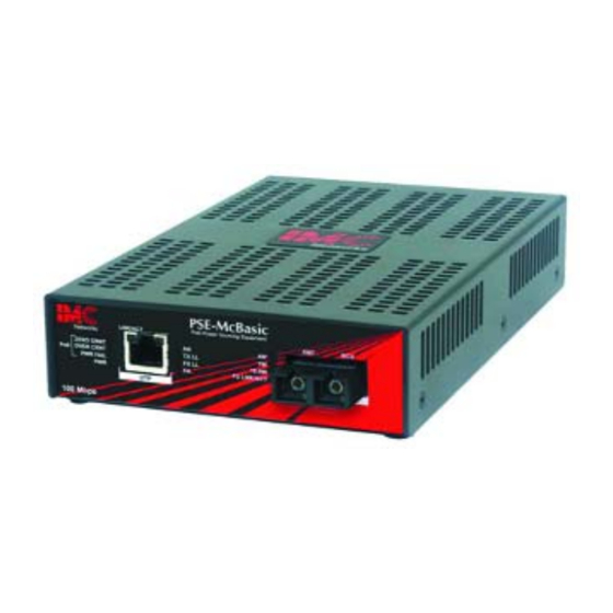
IMC Networks PSE-McBasic Operation Manual
Fiber-to-twisted pair media converter
Hide thumbs
Also See for PSE-McBasic:
- Features and benefits (2 pages) ,
- Supplementary manual (1 page) ,
- Operation manual (16 pages)
Table of Contents
Advertisement
Quick Links
Advertisement
Table of Contents

Related Manuals for IMC Networks PSE-McBasic


Summary of Contents for IMC Networks PSE-McBasic
- Page 1 PSE-McBasic Operation Manual...
-
Page 2: Fcc Radio Frequency Interference Statement
At its option, IMC Networks will repair or replace at no charge the product which proves to be defective within such warranty period. This limited warranty shall not apply if the IMC Networks product has been damaged by unreasonable use, accident, negligence, service or modification by anyone other than an authorized IMC Networks Service Technician or by any other causes unrelated to defective materials or workmanship. -
Page 3: Table Of Contents
Table of Contents FCC Radio Frequency Interference Statement ............ii Warranty........................ ii About the PSE-McBasic ..................1 About Power over Ethernet and PSE...............1 Installing the PSE-McBasic ..................1 Configuring the PSE-McBasic..................2 LinkLoss and FiberAlert ..................2 About the LED Indicators ..................6 Installation Troubleshooting ...................8 IMC Networks Technical Support................9... -
Page 4: About The Pse-Mcbasic
PSE detects it and supplies power. LEDs on the PSE-McBasic indicate the amount of power being supplied to the Powered Device (PD) as well as if the PSE-McBasic is over temperature or over current or has an open circuit. PSE functionality is enabled by default. -
Page 5: Configuring The Pse-Mcbasic
The PSE-McBasic features an 8-position DIP Switches, set after installation. Access these through a cut-out in the bottom of the unit. After configuring the DIP Switches, power cycle the PSE-McBasic for the changes to take effect. Default settings for the following features are shown to the right. -
Page 6: Link Integrity
The appropriate “LNK” (link) LED is lit to indicate this. The IMC Networks media converter also sends out link pulses from its copper and fiber transmitters, but normally has no way of knowing whether the cable to the other device is intact and the link pulses are reaching the other end. - Page 7 Pulsing FiberAlert Pulsing FiberAlert minimizes the problems associated with the loss of one strand of fiber. If a strand is unavailable, the IMC Networks device at the receiver end notes the loss of link. The device will stop transmitting data and start sending link pulses.
- Page 8 Full-Duplex Auto Negotiation is ON Auto Negotiation is ON Configure Auto Negotiation on a PSE-McBasic by adjusting the DIP Switch setting (for unmanaged modules) or via the management software. Refer to the DIP Switch table for switch location and settings.
-
Page 9: About The Led Indicators
The LED functions are: LNK/ACT Glows red when no device is connected to the PSE-McBasic or when the device is NOT a valid PD. The LED is off when the PSE-McBasic detects a valid PD. ZERO CRNT Glows red when no device is connected to the PSE-McBasic or when the device is NOT a valid PD. - Page 10 NOTE FiberAlert will not function when single-strand fiber is connected. Glows green when Powered Device consumes 3.84 watts to 4 watts of power (CLASS1 PD). Glows green when Powered Device consumes 6.49 watts to 7 watts of power (CLASS2 PD). 15.4W Glows green when Powered Device consumes 12.95 watts to 15.4 watts of power (CLASS0 PD).
-
Page 11: Installation Troubleshooting
When working with units whose features cannot be disabled, both twisted pair and fiber cables must be connected before the link LEDs will light. To test a PSE-McBasic by itself, first verify that an appropriate fiber patch cable is being used. Then, follow these steps:... -
Page 12: Imc Networks Technical Support
IMC Networks Technical Support Tel: (949) 465-3000 or (800) 624-1070 (in the U.S. and Canada); +32-16-550880 (Europe) Fax: (949) 465-3020 E-Mail: techsupport@imcnetworks.com Web: www.imcnetworks.com Specifications Environmental Operating Temperature -32° F to 122° F (-0° C to 50° C) Storage Temperature -4°... -
Page 13: Fiber Optic Cleaning Guidelines
Dust caps are installed at IMC Networks to ensure factory-clean optical devices. These protective caps should not be removed until the moment of connecting the fiber cable to the device. Should it be necessary to disconnect the fiber device, reinstall the protective dust caps. -
Page 14: Electrostatic Discharge Precautions
Electrostatic Discharge Precautions Electrostatic discharge (ESD) can cause damage to any product, add-in modules or stand alone units, containing electronic components. Always observe the following precautions when installing or handling these kinds of products Do not remove unit from its protective packaging until ready to install. Wear an ESD wrist grounding strap before handling any module or component. -
Page 15: Safety Certifications
Directive on Electrical Equipment Designed for use within Certain Voltage Limits (2006/95/EC). Certified to Safety of Information Technology Equipment, Including Electrical Business Equipment. For further details, contact IMC Networks. Class 1 Laser product, Luokan 1 Laserlaite, Laser Klasse 1, Appareil A’Laser de Classe 1... - Page 16 The information in this document is subject to change without notice. IMC Networks assumes no responsibility for any errors that may appear in this document. PSE McBasic Trademark of IMC Networks. Other brands or product names may be trademarks and are the property of their respective companies.
Need help?
Do you have a question about the PSE-McBasic and is the answer not in the manual?
Questions and answers