Table of Contents
Advertisement
Quick Links
Advertisement
Table of Contents

Related Manuals for IMC Networks iMcV-T1/E1/J1


Summary of Contents for IMC Networks iMcV-T1/E1/J1
- Page 1 Operation Manual...
-
Page 2: Fcc Radio Frequency Interference Statement
At its option, IMC Networks will repair or replace at no charge the product which proves to be defective within such warranty period. This limited warranty shall not apply if the IMC Networks product has been damaged by unreasonable use, accident, negligence, service or modification by anyone other than an authorized IMC Networks Service Technician or by any other causes unrelated to defective materials or workmanship. -
Page 3: Table Of Contents
Table of Contents FCC Radio Frequency Interference Statement ............ii Warranty......................ii About the iMcV-T1/E1/J1 ...................4 Contents ......................4 Prerequisites ......................4 Configuration .....................5 Installation ......................7 Description of DIP Switch-Selectable Options ..........11 Testing ......................15 Specifications ....................19 Safety Certifications..................20... -
Page 4: About The Imcv-T1/E1/J1
• Make sure that T1 UTP lines DO NOT use simplex power (no wet lines). • Before you install the iMcV-T1/E1/J1 modules you must verify the DIP switches are configured for the feature wanted. • Make sure you deploy the iMcV-T1/E1/J1 modules in pairs. -
Page 5: Configuration
NRZ Selection:............Disable NRZ (Passive Mode) You can use the iView management software to change some of the iMcV-T1/E1/J1 features after installing the modules in the chassis. Refer to the iView online help for more information. Passive Mode It is recommended that you use the default Passive mode configuration for most typical applications. - Page 6 Available configurations enabled by DIP switches (and iView T1 Mode Configurations (default) E1 Mode Configurations • Receive Equalizer Gain Limit (EGL) iView • Receive Equalizer Gain Limit (EGL) iView o -36 dB (Long Haul) o -12 dB (Short Haul) o -30 dB (Limited Long Haul) (default) o -43 dB (Long Haul) •...
-
Page 7: Installation
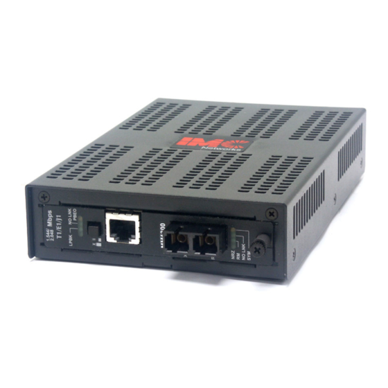
Installation At the central location the iMcV-T1/E1/J1 unit is typically installed in a managed chassis such as the iMediaChassis or the iMediaCenter. iMediaChassis iMediaCenter... - Page 8 Crossover/Straight-Through Connection iMcV-T1/E1/J1 comes with an RJ48 UTP connector that features a push-button switch, located next to the port, for selecting a crossover workstation or straight- through connection. To select a cross-over connection, press the push-button IN. A straight-through connection is selected when the push-button is OUT.
- Page 9 DIP Switch Table T1/E1 Selection S2-1: OFF T1 Mode Selected default S2-1: ON E1 Mode Selected Receive Equalizer Gain Limit (EGL) iVIEW S2-2: ON -12 dB (Short Haul) iVIEW S2-2: OFF -43 dB (Long Haul) iVIEW iVIEW S2-2: ON -36 dB (Long Haul) iVIEW iVIEW S2-2: OFF...
-
Page 11: Description Of Dip Switch-Selectable Options
Unmanaged Modules Before installing the iMcV-T1/E1/J1 module into an unmanaged chassis, configure the module hardware-selectable features via DIP switches located at position S3 and S2 on the PCB (refer to the DIP Switch Table section for more information). The jumpers located at positions JP1 and JP2 are factory configured—... - Page 12 Receive LIU Termination (Line Termination) This option allows you to set the receive termination. This is used to properly terminate cables in order to prevent signal reflections which can cause signal degradation. Transmit Data Source This option allows you to set the module to send normal data (default) or to send specific test-patterns of data to determine problems along the cable as a diagnostic tool.
-
Page 13: Remote Management
Remote Management This option allows you to enable Remote management on the module. The remote management feature is designed to work only on the remote module of the Local/Remote pair. With Remote management enabled, you can easily perform the following: •... - Page 14 PBEO Only used when the Transmit Data Source option is set to Pseudo-random Bit Sequence. This LED will glow amber when the iMcV-T1/E1/J1 module receives errors and will stay dark when the converter receives a Pseudorandom Bit Sequence without errors.
-
Page 15: Testing
Verify that the NO LNK LED for the fiber port is off. For single-strand fiber products, connect a single fiber cable from the Local iMcV-T1/E1/J1 to the remote iMcV-T1/E1/J1. Verify that the NO LNK LED for the fiber port is off. - Page 16 The iMcV-T1/E1/J1 can be configured to use the following loopback test modes: • Local Fiber Loopback Mode This setting tests the path from the CO copper port to the Local iMcV-T1/E1/J1 module fiber port and back. • Remote Fiber Loopback Mode This setting tests the path from the CO copper port to the Remote iMcV-T1/E1/J1 module fiber port and loops it back.
- Page 17 (DIP switch S3-3=Off and S3-4=On). This configuration allows you to test the path from the CO copper port to the Remote iMcV-T1/E1/J1 module fiber port and loop it back. The transmitted data is sent unhindered and the received data is ignored.
- Page 18 Testing with Pseudorandom Bit Sequence (PRBS) To test the copper segment from the Remote module to the Customer Premises Equipment (CPE) by using PRBS, perform the following: Set the CPE to loopback the signal. Set the Remote module to generate PRBSs (DIP switch S2-9=On and S2-10=Off).
-
Page 19: Specifications
Specifications Power Consumption (Typical): 0.550 Amp Operating Temperature: 32° to 122° F (0° to 50° C) Storage Temperature: 0° to 160°F (-20° to 70° C) Humidity: 5 to 95% (non-condensing); 0 to 10,000 ft. altitude Dimensions: Single Slot iMcV module Fiber Optic Specifications For fiber optic specifications, visit our Web site at www.imcnetworks.com. -
Page 20: Safety Certifications
Electrical Equipment Designed for use within Certain Voltage Limits (73/23/EEC). Certified to Safety of Information Technology Equipment, Including Electrical Business Equipment. For further details, contact IMC Networks. Class 1 Laser product, Luokan 1 Laserlaite, Laser Klasse 1, Appareil A’Laser de Classe 1... - Page 21 The information in this document is subject to change without notice. IMC Networks assumes no responsibility for any errors that may appear in this document. iMcV-T1/E1/J1 is a trademark of IMC Networks. Other brands or product names may be trademarks and are the property of their respective companies.
Need help?
Do you have a question about the iMcV-T1/E1/J1 and is the answer not in the manual?
Questions and answers