IMC Networks McBasic Operation Manual
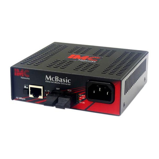
Ethernet media converter
Hide thumbs
Also See for McBasic:
- Installation manual (4 pages) ,
- Features and benefits (2 pages) ,
- Specifications (1 page)
Table of Contents
Advertisement
Quick Links
Download this manual
See also:
Installation Manual
Advertisement
Table of Contents

Subscribe to Our Youtube Channel
Related Manuals for IMC Networks McBasic


Summary of Contents for IMC Networks McBasic
- Page 1 McBasic Operation Manual...
-
Page 2: Fcc Radio Frequency Interference Statement
At its option, IMC Networks will repair or replace at no charge the product which proves to be defective within such warranty period. This limited warranty shall not apply if the IMC Networks product has been damaged by unreasonable use, accident, negligence, service or modification by anyone other than an authorized IMC Networks Service Technician or by any other causes unrelated to defective materials or workmanship. -
Page 3: Table Of Contents
Table of Contents FCC Radio Frequency Interference Statement ...ii Warranty...ii About the McBasic ...4 Installing the McBasic...4 Configuring McBasic ...4 Twisted Pair Crossover/Straight-Through Switch...4 BNC Port Termination...5 LinkLoss and Pulsing FiberAlert ...5 LED Operation...8 Installation Troubleshooting ...10 Specifications ...11 Safety Certifications...13... -
Page 4: About The Mcbasic
McBasic comes ready to install; configure after installation. To install McBasic, first make sure that the unit is placed on a suitable flat surface. Attach the cables between the McBasic and each device that will be interconnected, then plug the unit into a reliable, filtered power source. -
Page 5: Bnc Port Termination
Termination must be OFF (disabled). Termination is disabled when the switch is in the left position. If a thin Ethernet segment is to be terminated at the McBasic TP/BNC, attach the cable directly to the BNC connector and set the termination switch to ON (enabled –factory default) by moving the switch to the right position. - Page 6 The appropriate “LINK” LED is lit to indicate this. The IMC Networks media converter also sends out link pulses from its copper and fiber transmitters, but normally has no way of knowing whether the cable to the other device is intact and the link pulses are reaching the other end.
- Page 7 Pulsing FiberAlert minimizes the problems associated with the loss of one strand of fiber. If a strand is unavailable, the IMC Networks device at the receiver end notes the loss of link. The device will stop transmitting data and start sending link pulses.
-
Page 8: Led Operation
LED Operation Each McBasic features diagnostic LEDs. The following illustrations show the location of the LEDs, and other features, on McBasic TP/FO and McBasic TP/BNC. The LED functions for McBasic TP/FO are as follows: • TP LINK Glows green if link is established on the TX port. - Page 9 • BNC RCV Flickers amber when BNC port is receiving data (On a -20 McBasic TP/BNC, the TP RCV and BNC RCV LEDs flicker at a rate proportional to the rate that the data is passing on the ports. Under low traffic conditions, the LEDs flicker...
-
Page 10: Installation Troubleshooting
Next Generation product. • When connecting the fiber port of a McBasic TP/FO to a 100 Mbps fiber port of the link partner or another media converter ,an unlabeled LED located at the top of the fiber LED stack will glow amber, indicating the presence of a configuration fault. -
Page 11: Specifications
Specifications Power AC Input Load: 100/240V±10% ~ 50/60 Hz, 0.1/0.05A Operating Temperature: 32° to 104° F (0° to 40° C) Storage Temperature: -4° to 158° F (-20° to 70° C) Humidity: 5 to 90% (non-condensing); 0 to 10,000 ft. altitude Shipping weight: 1.3 lbs. - Page 12 Dimensions: McBasic TP/FO 1.68”H x 4.75”W x 4.95”D (4.3 cm x 12.1 cm x 12.6 cm) McBasic TP/BNC 1.68"H x 4.75"W x 4.53"D (4.3 cm x 12.1 cm x 11.5 cm)
-
Page 13: Safety Certifications
Electrical Equipment Designed for use within Certain Voltage Limits (73/23/EEC). Certified to Safety of Information Technology Equipment, Including Electrical Business Equipment. For further details, contact IMC Networks. Class 1 Laser product, Luokan 1 Laserlaite, Laser Klasse 1, Appareil A’Laser de Classe 1... - Page 14 The information in this document is subject to change without notice. IMC Networks assumes no responsibility for any errors that may appear in this document. McBasic is a trademark of IMC Networks. Other brands or product names may be trademarks and are the property of their respective companies.
Need help?
Do you have a question about the McBasic and is the answer not in the manual?
Questions and answers