Premier Mounts CTM-MS2 Installation Manual
Hide thumbs
Also See for CTM-MS2:
- Installation instructions manual (12 pages) ,
- Specifications (2 pages) ,
- Installation instructions manual (11 pages)

Related Manuals for Premier Mounts CTM-MS2


Summary of Contents for Premier Mounts CTM-MS2
-
Page 1: Installation Manual
INSTALLATION MANUAL CTM-MS2 Premier Mounts 3130 E. Miraloma Avenue Anaheim, CA 92806 Phone: (800) 368-9700 Fax: (800) 832-4888 mounts@mounts.com www.mounts.com IN-CTMMS2.R2... - Page 2 PBL-110 Projector Mount Page - 2 - Installation Manual...
-
Page 3: Table Of Contents
Installation Tools ..............................- 5 - Mounting Bracket Installation ........................- 9 - CTM-MS2 Installation ..........................- 12 - Installing the Flat Panel Display (CTM-MS2) ....................- 14 - Technical Specifications ..........................- 17 - Warranty ................................- 18 - Contact Premier Mounts ..........................- 18 - Notes ................................- 19 -... -
Page 4: Warning Statements
CTM-MS2 Warning Statements WARNING: THE WALL STRUCTURE MUST BE CAPABLE OF SUPPORTING 160 LBS. IF NOT, THE WALL STRUCTURE MUST BE REINFORCED. PROPER INSTALLATION PROCEDURE BY A QUALIFIED SERVICE TECHNICIAN, AS OUTLINED IN THE INSTALLATION INSTRUCTIONS, MUST BE ADHERED TO. FAILURE TO DO SO COULD RESULT IN SERIOUS PERSONAL INJURY, OR EVEN DEATH. -
Page 5: Parts List
This wall mount is shipped with all proper installation hardware and components. Make sure that none of these parts are missing and/or damaged before beginning installation. If there are parts missing and/or damaged, please stop the installation and contact Premier Mounts (800-368-9700). - Page 6 CTM-MS2 (Qty 8) (Qty 6) M4 x 16 M6 x 20 (Qty 4) M4 x 25 (Qty 2) M6 x 30 (Qty 8) M5 x 12 M8 x 20 (Qty 6) (Qty 6) M5 x 16 (Qty 6) M5 x 20...
- Page 7 CTM-MS2 Nylon spacers and flat washers actual size NOTE: The nylon spacers may be stacked to achieve proper spacing. 9/16" Nylon spacers 1/4" Nylon spacers (large) (Qty 6) (Qty 6) 1/2" Nylon spacers Nylon sleeves (large) (Qty 4) (Qty 12) 5/16"...
-
Page 8: Thread Depth Indicator
CTM-MS2 Thread Depth Indicator Insert the thread depth indicator (supplied) through the thread inserts found on the back of the flat panel to make sure the inserts measure the same full depth and mark it (Figure 1). Locate the correct diameter screw for the thread insert. Compare your marking to the screws (supplied). -
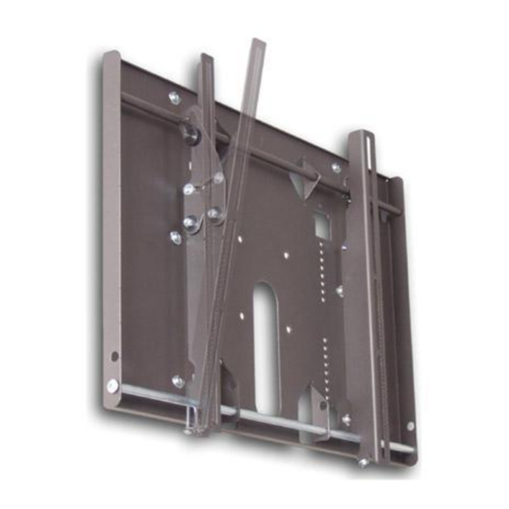
Page 9: Mounting Bracket Installation
CTM-MS2 Mounting Bracket Installation NOTE: Proper installation procedure by qualified personnel as outlined in the installation instructions must be adhered to. Failure to do so could result in serious personal injury and possible damage to the flat panel. WARNING: INVERT THE FLAT PANEL PLACE IT ON A SOFT, FLAT SUFRACE TO PREVENT DAMAGE TO THE FLAT PANEL. - Page 10 CTM-MS2 Install the nylon spacers (if needed) to the mounting points on the flat panel (Figure 6). Lay the left and right mounting brackets (stamped arrows facing out) - (Figure 7). Nylon Spacers, If Applicable Mounting Brackets Center Mark Inverted Flat Panel...
- Page 11 CTM-MS2 Mounting Bracket Bottom of Flat Panel Center of Viewing Guide Center of Flat Bottom of the Align the Mounting Panel Flat Panel Brackets Figure 8 Figure 9 The Griplates™ have M4, M5 M6 and M8 hole patterns to fit the hardware that your flat panel requires.
-
Page 12: Ctm-Ms2 Installation
CTM-MS2 CTM-MS2 Installation Using a (commercially available) wood stud finder, locate the 16" or 24" stud centers behind the wall (Figure 12). Once found, make a pencil marking on the center of the wood studs (Figure 13). NOTE: The wall plates have 16" and 24" mounting slot positions. - Page 13 CTM-MS2 Level the wall plate with the reference arrow pointing up to the ceiling (Figure 15). Drill six (6) ¼" pilot holes to the marked wall. Secure the plate using the six (6) 5/16" lag bolts and flat washers (Figure 16).
-
Page 14: Installing The Flat Panel Display (Ctm-Ms2)
CTM-MS2 Installing the Flat Panel Display (CTM-MS2) WARNING: AT LEAST (2) QUALIFIED PERSONNEL ARE STRONGLY RECOMMENDED FOR INSTALLATION OF THIS PRODUCT. FAILURE TO DO SO COULD RESULT IN SERIOUS INJURY AND POSSIBLE DAMAGE TO THE FLAT PANEL. Raise the flat panel with the LEFT and RIGHT mounting brackets secured to the flat panel and insert the top hooks over the upper rod. - Page 15 CTM-MS2 Make any lateral shift adjustment and lock it by tightening the two (2) M6 x 30mm Phillips screws found on the bottom of the mounting brackets. Use the foot leveler to adjust your plasma. CAUTION: Do not over tighten the M6 x 30mm screws to the rods (Figure 18).
- Page 16 CTM-MS2 Tilt the flat panel and secure the two (2) M6 x 12mm safety knobs to each of the mounting brackets (Figure 19). NOTE: To remove the display from the wall simply extend the display to its maximum tilt range, remove the two 6 (mm) safety knurl knobs push the flat panel back to it’s flat position, loosen or remove...
-
Page 17: Technical Specifications
CTM-MS2 Technical Specifications 28.000 (171.2) 8.000 (203.2) 21.000 19.000 (533.4) (482.6) 8.000 (203.2) 16.000 (406.4) 24.000 (616.97) 2.331 (59.21) 12° 19.000 (482.6) A. Wall plate B. Mounting brackets C. Griplate™ D. Mounting hardware E. M6 x 30 (mm) Phillip screws F. -
Page 18: Warranty
Warranty Limited Lifetime Warranty All Premier Mounts products carry a limited lifetime warranty from ship date against defects in materials and workmanship. Premier Mounts is not liable for improper installation that results in damage to mounts, adapters, display equipment or personal injury. -
Page 19: Notes
CTM-MS2 Notes Premier Mounts 3130 E. Miraloma Avenue Anaheim, CA 92806 Phone: (800) 368-9700 Fax: (800) 832-4888 mounts@mounts.com www.mounts.com IN-CTMMS2.R2 Installation Manual Page 19... - Page 20 AST-2446/2 Suspension Adapter AST-2446/2 INSTALLATION INSTRUCTIONS Separate the upper pipe and lower tube. Install the upper pipe to the ceiling structure using commercial standards and commercially available suitable hardware (Figure 1). Once the upper pipe has been properly secured to the ceiling structure. Screw the base box or any ceiling adapters to the lower portion of the AST-2446 and secure it with the jam nut (supplied).
- Page 21 AST-2446/2 Suspension Adapter Figure 2. Figure 3. Page 2 Installation Instructions...
- Page 22 PSD-S PSD-S INSTALLATION INSTRUCTIONS 1. Separate the upper pipe and the lower tube. 2. Install the upper pipe in the ceiling structure using suitable commercial hardware. 3. Screw the lower portion of the PSD-S to the coupling and secure with the Allen screws. 4.
Need help?
Do you have a question about the CTM-MS2 and is the answer not in the manual?
Questions and answers