Premier Mounts PCM-MS2 Installation Instructions Manual
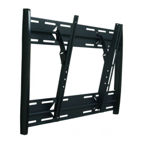
Universal flat panel mount
Hide thumbs
Also See for PCM-MS2:
- Installation instructions manual (13 pages) ,
- Specifications (2 pages) ,
- Installation manual (22 pages)
Table of Contents
Advertisement
Quick Links
Download this manual
See also:
Installation Manual
NORTH AMERICA
3130 East Miraloma Avenue
Anaheim, CA 92806 USA
USA and Canada –
Phone: 800-368-9700
Fax: 800-832-4888
Other Locations – Phone: (001)-714-632-7100; Fax: (001)-714-632-1044
©Premier Mounts 2008
9531-000-501-03
INSTALLATION INSTRUCTIONS
PCM-MS2
Universal Flat Panel Mount
EUROPE
Swallow House,
Shilton Industrial Estate,
Shilton, Coventry, England CV79JY
Phone: +44 (0) 2476 614700
Fax: +44 (0) 2476 614710
AUSTRALIA, NEW ZEALAND, OCEANIA
(DISTRIBUTOR)
P.O. Box 295
Mordialloc Victoria 3195
Australia
Phone: 039586 6330
www.premiermounts.com.au
Advertisement
Table of Contents

Subscribe to Our Youtube Channel
Related Manuals for Premier Mounts PCM-MS2


Summary of Contents for Premier Mounts PCM-MS2
- Page 1 Mordialloc Victoria 3195 USA and Canada – Shilton, Coventry, England CV79JY Australia Phone: 800-368-9700 Phone: +44 (0) 2476 614700 Phone: 039586 6330 Fax: 800-832-4888 Fax: +44 (0) 2476 614710 www.premiermounts.com.au Other Locations – Phone: (001)-714-632-7100; Fax: (001)-714-632-1044 ©Premier Mounts 2008 9531-000-501-03...
-
Page 2: Table Of Contents
Warranty ................................- 18 - Warning Statements PREMIER MOUNTS DOES NOT WARRANT AGAINST DAMAGE CAUSED BY THE USE OF ANY PREMIER MOUNTS PRODUCT FOR PURPOSES OTHER THAN THOSE FOR WHICH IT WAS DESIGNED OR DAMAGE CAUSED BY UNAUTHORIZED ATTACHMENTS OR MODIFICATIONS, AND IS NOT RESPONSIBLE FOR ANY... -
Page 3: Parts List
This wall mount is shipped with all proper installation hardware and components. Make sure that none of these parts are missing and/or damaged before beginning installation. If there are parts missing and/or damaged, please stop the installation and contact Premier Mounts (800-368-9700). Mounting... - Page 4 PCM-MS2 (Qty 8) M4 x 16 (Qty 6) M6 x 20 (Qty 4) M4 x 25 (Qty 6) M8 x 20 (Qty 8) M5 x 12 (Qty 6) M5 x 16 (Qty 6) M8 x 25 (Qty 6) M5 x 20...
- Page 5 PCM-MS2 Nylon spacers and flat washers NOTE : The nylon spacers may be stacked to achieve proper spacing. " Nylon Spacers " Nylon Spacers (Large) (Qty 6) (Qty 6) " Nylon Spacers (Large) Nylon Sleeves (Qty 12) (Qty 4) " Flat Washers...
- Page 6 PCM-MS2 Thread Depth Indicator Insert the thread depth indicator (supplied) through the thread inserts found on the back of the flat panel to make sure the inserts measure the same full depth and mark it. Locate the correct diameter screw for the thread insert. Compare your marking to the screws (supplied).
-
Page 7: Finding The Center Of The Plasma Display
PCM-MS2 Finding the Center of the Plasma Display Proper installation procedure by qualified personnel as outlined in the installation instructions must be adhered to. Failure to do so could result in serious personal injury and possible damage to the flat panel. -
Page 8: Positioning The Mounting Brackets
PCM-MS2 Positioning the Mounting Brackets If your display has uneven mounting points, or recessed mounting points, please use the provided spacers (Page 5). Step 1. Install the nylon spacers to the mounting points on the flat panel. If the nylon spacers apply to your flat panel, please see Page 5. - Page 9 PCM-MS2 Step 3. Match the center of viewing guide with the center line you marked in step 1. Step 4. The mounting brackets are designed with a center of viewing guide on the side of them. Installation Manual Page 14...
-
Page 10: Securing The Mounting Brackets
PCM-MS2 Securing the Mounting Brackets The Griplate™ have M4, M5 M6 and M8 hole patterns to fit the hardware that your flat panel requires. EXAMPLE: If your plasma uses M8 x 20 Phillip screws, use the M8 mounting points. Step 1. Pre-install two (2) M6 x 30 (mm) Phillip pan screws to the bottom of the left and right hand side mounting brackets. -
Page 11: Marking The Wall
PCM-MS2 Marking the Wall Step 1. Align the center viewing port from the carton template to the wall. Step 2. Match the center of viewing port to the center of viewing height desired. Step 3. Mark a line on the bottom of the carton template. -
Page 12: Marking The Bottom Plate Mounting Points
PCM-MS2 Marking the Bottom Plate Mounting Points Step 1. Place the upper portion of the bottom wall plate to the reference line and mark the four (4) lag bolt mounting points through the wall plate slots on the wall. Step 2. Level the wall plate with the reference arrow pointing up to the ceiling. -
Page 13: Securing The Bottom Wall Plate
PCM-MS2 Securing the Bottom Wall Plate Step 1. Level and secure the plate to the wall with the reference arrow facing up to the ceiling. Step 2. Secure the plate using (commercially available) suitable hardware depending on your installation environment. -
Page 14: Securing The Top Plate
PCM-MS2 Securing the Top Plate Step 1. Drill four (4) ¼" pilot holes to the marked Step 2. Level and secure the plate to the wall with the reference arrow facing up to the ceiling. Step 3. Secure the plate using (commercially available) suitable hardware depending on your installation environment. -
Page 15: Securing The Plasma To The Wall Mount
PCM-MS2 Securing the Plasma to the Wall Mount AT LEAST (2) QUALIFIED PERSONNEL ARE STRONGLY RECOMMENDED FOR INSTALLATION OF THIS PRODUCT. FAILURE TO DO SO COULD RESULT IN SERIOUS INJURY AND POSSIBLE DAMAGE TO THE FLAT PANEL. Step 1. Raise the flat panel with the mounting brackets secured to the flat panel and insert the top and bottom hooks from each bracket to the rods from the wall plates. -
Page 16: Lateral Shift Adjustment
PCM-MS2 Lateral shift adjustment Step 1. Tilt the flat panel and secure the two (2) M6 x 12 mm) safety knobs to each of the mounting brackets. To remove the display from the wall simply extend the display to its maximum tilt range, remove the two 6 (mm) safety knurl knobs push the flat panel back to it’s flat position loosen or remove the two (2) M6 x 30 lateral shift... -
Page 17: Technical Specifications
PCM-MS2 Technical Specifications All measurements are in inches(mm). Installation Manual Page 14... -
Page 18: Warranty
What Premier Mounts Will Do At the sole option of Premier Mounts, Premier Mounts will repair or replace any product or product part that is defective. If Premier Mounts chooses to replace a defective product or part, a replacement product or part will be shipped to you at no charge, but you must pay any labor costs.
Need help?
Do you have a question about the PCM-MS2 and is the answer not in the manual?
Questions and answers